Advertisement
Quick Links
Advertisement

Related Manuals for Epson C82302/04 (Serial I/F


Summary of Contents for Epson C82302/04 (Serial I/F
- Page 1 EPSON 32KB Serial Interface...
- Page 2 INTRODUCTION The Serial Interface C82302* / C82304* is an interface board that allows asynchronous serial data communica- tion between a host computer and an Epson printer. features: This board a 32K byte buffer that frees up your computer for other uses while your printer continues to print.
-
Page 3: About This Guide
About this guide This guide is designed to give you detailed information how to install your C82302* / C82304* serial interface in a variety of Epson printers. Installation board procedures vary slightly depending upon the printer that you have. model... -
Page 4: Setting The Conditions
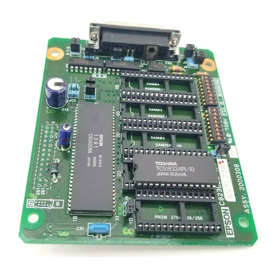
SETTING THE CONDITIONS The C82302*/C82304* interface board has two sets of jumpers. DIP (Dual In-line Package) switches, and 16 These switch& and jumpers are used for selecting various interface operations. Board layout The figure below shows the layout of the C82302*/ the DIP C82304* board, and the locations of switches... - Page 5 The c82302*/c82304* interface board has two sets of DIP (Dual in-line Package) switches, and 16 jumpers. These switches and jumpers are used for selecting various interface operations. Board layout The figure below shows the layout of the (C82302*/ C82304* board, and the locations of the DIP switches and jumpers.
- Page 6 ~qJqhstalltheCgL302*/-~krfaa,you nutyncedtoadjustsomeofthe=kings. Whennuking DIp&t&Kttin chan~,itbbUttO~SpOinted dtice,suchasa fall -point pen oramalllsawdljver. CSUtiOll All changes of DIP switch and jumper settings show are made with the printer power turned off. the printer chacks and recognizes new settings only at the time the power i s turned on About DIP switches The two sets of DIP switches on the C82302*/C82304*...
- Page 7 DIP switch 1(Interface operations) The table below contains information on switch func- tions, and the factory setting switch. of each switches on DIP switch 1 allow you to change interface functions. 1- DIP smitch 1 Table L - - - - - - - ‘z (bib 7bth...
- Page 8 Data word structure The data word structure is also operator selectable through DIP switch settings (see Table 1). The word structure for serial data is: 1 start bit + 7 or 8 data bits (selectable) + 1 Even or Odd parity bit (optional) + 1 or more stop bits The table below shows the possible word structure Combinations.
- Page 9 the printer buffer is enabled. The buffer is a memory which can temporarily store data from a computer. Table 3. Band rate selection Note Switch combinations other than those shown above will be taken as a setting for...
- Page 10 Dip switch 2 (interface operations) The table below contains information switch func- tions, and the factory setting of each switch The switches on DIP switch 2 allow you to change interface functions and select the self test modes . Note This interface board operates when DIP switch 2-1 is turned on.
- Page 11 Buffer full recovery timing When the available space for bytes in the print buffer drops to 512 or 16 bytes, data entry is disabled. As the printer prints the data in the buffer, the vacant area for bytes increases. when this vacant area reaches one of cation is resumed.
-
Page 12: Jumper Settings
Jumper settings The tables below give you information about the interface conditions that can be selected using jumpers. In all cases, ON denotes the connection of the jumper (covering both terminals), while OFF denotes the disconnection of the jumper. - Page 13 If the host computer is not equipped with a power supply for the Current loop interface, these jumpers must be connected to perform communica- tion via the Current loop interface Either J8 or j9 jumper is connected at the factory, and you should not change this setting Either JCX or JCF jumper must be connected.
- Page 14 serial data communications The C82302*/C82304 interface allows you to select either RS-232C or 20 mA Current Loop signal leve data communication but never both at the same time This interface board also provides for either DTR (Data Terminal Ready) or X-on/X-off handshaking protocol. About data entry To accommodate data entry, the C82302*/C82304* interface board is equipped with a buffer that temporar-...
- Page 15 Handshaking p r o t o c o l x-on/x-off Protocol X-on/X-off protocol is a system in which the printer transmits a code to the computer to indicate that it cannot accept more data, and a second code when it is once again ready.
- Page 16 Tmusnrit timing ofXon signal neX4nt6lgnalis-tiwhe!nthepowerisfirst tumedon,orwhenthevauntaminthebufferk greater than the preset value of the buffer recovery timing. Refer to Table 5. for buffer recovery timing information Figure 3. X-on/x-off timing DTR protocol This interface board also provides for DTR handshaking protocol using either RS-232C or Current Loop signal levels Under this system, when the printer is turned on the DTR enters the SPACE state, meaning that data entry is...
- Page 17 WhenthtMcl n tUeafor ’ tucontinuatopxinL ra&u~thepresetreaweryvaIue(seeTab~5Me flagisresetanddataartybagainarrbled- Note ~channtl(pinNo.11~andDTR~~No.zD~uc intwLuyamneckdontheinterfaaboardandmwt have idmtid signal levds. When buffer operation is disabled UAdatttiswnditi~the5gisoutputfromtheDTR (pinNo.u))intheQseofRs232GudfromLhc’I?y- I7CD@inNo.l7EnthecaseofCumnt~. DukngbufferdisabledoperatioAonlyasi@bytcof dataanbehandledatatime OMetheinm transfersabyteofdabtotheprhkr,thcstatus5gWill be~Afterthfsdataisprillt6d,th65gwiIlrr#t,d &laeAtlywilIbeenabledagah PriAterrhtustrrm lhe5gwilIbesetimmedlately~essdthc rex&iIlgbufferupalityifthepriA~mchaa6trkd e r r o r . lheerrorsignalQinNo.lof~winthcnk low.
- Page 18 nwseutatmodaankdtcredbyDIPswit&,2-7 d24. Toselectasdftestmukfhttumofftht powatOthtphlbEfd~~changeDIPSWitch settbg. wluAtkpowerLtumedba~ohthencw settings automatiully WmC intO tffuL To i&n t& 8&tES&tWIloffthcpowaudrl%!tth4?DIPswiteha. Self modes Table 9.
-
Page 19: Specifications
SPECIFICATIONS Synchronizing Method: Asynchronous Baud Rate: 75,110,134.5,150,200,300,600,1200, 1800,2400,4800,9600,19200 BPS (selectable) Word length: 1 bit Start bit: 7 or 8 bits klectable) Data bit: Parity bit: Odd, even or none (selectable) 1 bit or more Stop bit: Input signal polarity: 1) WithRS232Cz MARK = logic “1”... - Page 20 5. Handshaking Tub& 10. Handshaking ccmtrol laop RW32C w-hmtheimpedme usingMRFrotoco1* whcntherigvl conditionrtpinN0.11 bawccnpinNo.17 andpinNo.ML: andpinNo.2Ois: WWOVlARJQI)rtA ~~~t.Lnhyh enhyidiubled. mmisbnsmittedby EsXaN/Xam Datl is-ttd tbedungeoftbe fmmpinNo.2 impedAncebctwcen ~4x4 CY I>K mm entIyisenAbld. pinNo.17andpin No. 24. xam CI~X~Z mktr 4btf entry h disabled. entry is enabled.
- Page 21 I/F board connector EIA standard 25-pin Cannon type. For signal description and pin assignment, refer to the table below: Table 11. Signal and Pin Assignment Description IPin No. 1 Simul Nmc 1Dirution’ DcraiptiOll Protectiw -gmund Gnlund Truumitted TrrMmitted 5eriAl data o u t Data CIXD) Rquat to...
- Page 22 Note The column heading “Direction” refers to the direction of signal flow as viewed from the printer. All signals except TTY-TXD and TTY-RXD comply with EIA RS-232C standard.
- Page 23 RECOMMENDED CIRCUIT CONNECTIONS Recommended line driver and line receiver for RS-232C signal level settings., (As viewed from the host com- puter.) Figure 4. RS-232C !Sefial Inteffaa Boafd MC 1499L 75199 or 0quivMnt Recommended line interface circuit for 20 mA Current Loop signal level settings.