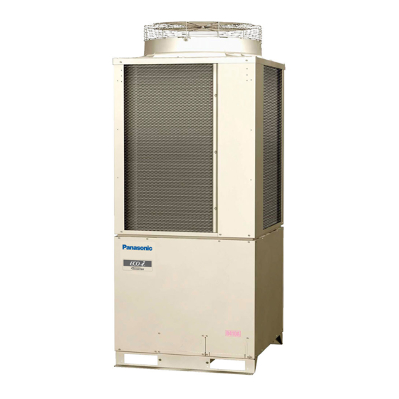
Panasonic U-72MF1U9 Technical Data Manual
3way vrf system
Hide thumbs
Also See for U-72MF1U9:
- Service manual (128 pages) ,
- Installation instructions manual (56 pages) ,
- Operating instructions manual (16 pages)
Table of Contents
Advertisement
Quick Links
U-72MF1U9
U-72MF1U9E
U-96MF1U9
U-96MF1U9E
Model No.
Outdoor Unit
Class
U-72MF1U9
Model Name
U-72MF1U9E*
Refrigerant R410A is used in the outdoor units.
* Salt-Air Damage Resistant Specifications.
Indoor Units
Class
U1
4-Way Cassette
Y1
4-Way Cassette 60×60
D1
1-Way Cassette
S-07MD1U6 S-09MD1U6 S-12MD1U6
F1
Low Silhouette Ducted
S-07MF1U6 S-09MF1U6 S-12MF1U6 S-15MF1U6 S-18MF1U6
M1
Slim Low Static Ducted
S-07MM1U6 S-09MM1U6 S-12MM1U6
High Static Pressure
E1
Ducted
T1
Ceiling
K1
Wall Mounted
S-07MK1U6 S-09MK1U6 S-12MK1U6
P1
Floor Standing
S-07MP1U6 S-09MP1U6 S-12MP1U6 S-15MP1U6 S-18MP1U6
Concealed Floor
R1
S-07MR1U6 S-09MR1U6 S-12MR1U6 S-15MR1U6 S-18MR1U6
Standing
**
Necessary to install the External Electronic Expansion Valve Kit (Optional:CZ-P56SVK1U)
85464869258000
*
*
72
96
U-96MF1U9
U-96MF1U9E*
7
9
12
S-12MU1U6
S-12MY1U6
S-15MM1U6 S-18MM1U6
S-12MT1U6
3WAY VRF System
15
18
19
S-18MU1U6
S-24MU1U6 S-36MU1U6
S-18MY1U6
S-24MF1U6
S-18MT1U6
S-24MT1U6
**
S-18MK1U6 S-19MS1U6
S-24MK1U6
S-24MP1U6
S-24MR1U6
24
36
48
S-36MF1U6 S-48MF1U6
S-54MF1U6
S-36ME1U6 S-48ME1U6
TD831158-00
REFERENCE NO.
Section
1
2
3
4
54
5
6
7
8
Advertisement
Table of Contents

Related Manuals for Panasonic U-72MF1U9


Summary of Contents for Panasonic U-72MF1U9
- Page 1 3WAY VRF System U-72MF1U9 U-72MF1U9E Section U-96MF1U9 U-96MF1U9E Model No. Outdoor Unit Class U-72MF1U9 U-96MF1U9 Model Name U-72MF1U9E* U-96MF1U9E* Refrigerant R410A is used in the outdoor units. * Salt-Air Damage Resistant Specifications. Indoor Units Class 4-Way Cassette S-12MU1U6 S-18MU1U6 S-24MU1U6 S-36MU1U6 4-Way Cassette 60×60...
- Page 2 thin aluminum fins on the air conditioner can cut your IMPORTANT! fingers. Please Read Before Starting When Installing… This air conditioning system meets strict safety and operating standards. As the installer or service person, it Select an installation location which is rigid and strong is an important part of your job to install or service the enough to support or hold the unit, and select a location system so it operates safely and efficiently.
- Page 3 When Servicing • Do not touch the air inlet or the CAUTION sharp aluminum fins of the • Turn the power OFF at the main power box (mains) outdoor unit. You may get injured. before opening the unit to check or repair electrical •...
- Page 4 Precautions for Installation Using New Refrigerant 1. Care regarding tubing 1-1. Process tubing Material: Use C1220 phosphorous deoxidized copper specified in JIS H3300 “Copper and Copper Alloy Seamless Pipes and Tubes.” For tubes of ø7/8" (ø22.22 mm) or larger, use C1220 T-1/2H material or H material, and do not bend the tubes. Tubing size: Be sure to use the sizes indicated in the table below.
- Page 5 3-2. Use R410A exclusive cylinder only. Valve Single-outlet valve (with siphon tube) Liquid refrigerant should be recharged with the cylinder standing on end as shown. Liquid New refrigerant R410A cannot be used for earlier models 1. Compressor specifications are different. If recharging a R22 or R407C compressor with R410A, durability will significantly decrease since some of the materials used for compressor parts are different.
-
Page 6: Table Of Contents
Contents Section 1: OUTLINE OF 3WAY VRF SYSTEM ..............Line-up ......................Features of 3WAY VRF SYSTEM ..............Salt-Air Damage Resistant Specifications ............Section 2: DESIGN OF 3WAY VRF SYSTEM ................ Model Selecting and Capacity Calculator ............System Design ..................... 2-18 Electrical Wiring .................... -
Page 7: Section 1: Outline Of 3Way Vrf System
Outline of 3WAY VRF SYSTEM Contents 1. OUTLINE OF 3WAY VRF SYSTEM 1. Line-up ..........................1-2 2. Features of 3WAY VRF SYSTEM ..................3. Salt-Air Damage Resistant Specifications ............... 1 - 1... -
Page 8: Line-Up
Outline of 3WAY VRF SYSTEM 1. Line-up Indoor units Type 4-Way Cassette (U1 Type) S-12MU1U6 S-18MU1U6 S-24MU1U6 S-36MU1U6 4-Way Cassette 60 X 60 (Y1 Type) S-12MY1U6 S-18MY1U6 1-Way Cassette (D1 Type) S-07MD1U6 S-09MD1U6 S-12MD1U6 Low Silhouette Ducted (F1 Type) S-07MF1U6 S-09MF1U6 S-12MF1U6 S-15MF1U6 S-18MF1U6 S-24MF1U6... - Page 9 Outline of 3WAY VRF SYSTEM 1. Line-up Outdoor units Type Capacity: BTU/h (kW) 72,000 (21.1) Cooling / Heating / 81,000 (23.7) Air intake U-72MF1U9 U-72MF1U9E * intake Outdoor Unit intake (Ceiling panel dimensions) Air discharge unit : in. Type Capacity: BTU/h (kW) 96,000 (28.1)
-
Page 10: Features Of 3Way Vrf System
System example Since all pipings are concentrated CONCENTRATION into one pipe shaft, you can minimize piping space and construction labor * Panasonic makes it possible to link outdoor CONNECTION unit together for a large capacity (24-Ton). Solenoid valve kit Indoor unit... - Page 11 Outline of 3WAY VRF SYSTEM 2. Features of 3WAY VRF SYSTEM Dimensions 6, 8 Ton intake 6-Ton U-72MF1U9, U-72MF1U9E* 8-Ton U-96MF1U9, U-96MF1U9E* intake intake intake 31-1/8 (Installation hole pitch) (Ceiling panel dimensions) Unit: in. Top view Dimensions of unit combinations...
- Page 12 Outline of 3WAY VRF SYSTEM 2. Features of 3WAY VRF SYSTEM Capacity control The compressor combination (DC inverter compressor + constant-speed compressor) allows smooth capacity control from 0.6-Ton to 24-Ton. Realization of smooth capacity control In case of 24-Ton system from 0.6-Ton to 24-Ton Capacity (Ton)
-
Page 13: Salt-Air Damage Resistant Specifications
Outline of 3WAY VRF SYSTEM 3. Salt-Air Damage Resistant Specifi cations Specifications Salt-Air Damage Resistant Specifications Relevant Parts Material Standard Specifications Outdoor unit model name ended with letters "U9E". Outer box/side plate/ Hot-dip zinc-coated Polyester powder double coating Polyester powder double coating drain pan steel sheet (both sides) (... - Page 14 – MEMO – 1 - 8...
-
Page 15: Section 2: Design Of 3Way Vrf System
Design of 3WAY VRF SYSTEM Contents 2. DESIGN OF 3WAY VRF SYSTEM 1. Model Selecting and Capacity Calculator ................ 2-2 1-1. Operating Range ......................1-2. Procedure for Selecting Models and Calculating Capacity ........... 1-3. Tubing Length ......................... 1-4. Tubing Size ........................1-5. -
Page 16: Model Selecting And Capacity Calculator
Design of 3WAY VRF SYSTEM 1. Model Selecting and Capacity Calculator 1-1. Operating Range Heating and Cooling Operating range Indoor air intake temp. F (DB) Heating Cooling Operating Operating range range Indoor air intake temp. F (DB) Indoor air intake temp. F (WB) 2 - 2... - Page 17 Design of 3WAY VRF SYSTEM 1. Model Selecting and Capacity Calculator 1-2. Procedure for Selecting Models and Calculating Capacity Model Selection Procedure Select the model and calculate the capacity for each refrigerant system according to the procedure shown below. Calculation of the indoor air-conditioning load Calculate the maximum air-conditioning load for each room or zone.
- Page 18 Design of 3WAY VRF SYSTEM 1. Model Selecting and Capacity Calculator 1-3. Tubing Length Select the installation location so that the length and size of refrigerant tubing are within the allowable range shown in the figure below. Main tubing length LM = LA + LB … < 262 ft Main distribution tubes LC –...
- Page 19 Design of 3WAY VRF SYSTEM 1. Model Selecting and Capacity Calculator Refrigerant Charge Amount at Shipment (for outdoor unit) U-72MF1U9 U-96MF1U9 U-72MF1U9E U-96MF1U9E (oz) Additional Refrigerant Charge Additional refrigerant charge amount is calculated from the liquid tubing total length as follows.
- Page 20 139,000 168,000 192,000 203,000 240,000 264,000 288,000 (kW) (21.1) (28.1) (40.7) (49.2) (56.3) (59.5) (70.3) (77.4) (84.4) Total system tonnage U-72MF1U9(E) U-96MF1U9(E) U-72MF1U9(E) U-96MF1U9(E) U-96MF1U9(E) U-72MF1U9(E) U-96MF1U9(E) U-96MF1U9(E) U-96MF1U9(E) Combined outdoor U-72MF1U9(E) U-72MF1U9(E) U-96MF1U9(E) U-72MF1U9(E) U-72MF1U9(E) U-96MF1U9(E) U-96MF1U9(E) models U-72MF1U9(E)
- Page 21 Design of 3WAY VRF SYSTEM 1. Model Selecting and Capacity Calculator Table 2-5 Amount of Refrigerant Charge Liquid tubing size Amount of refrigerant (in. (mm)) charge (oz/ft.) ø1/4" (ø6.35) 0.279 ø3/8" (ø9.52) 0.602 ø1/2" (ø12.7) 1.38 ø5/8" (ø15.88) 1.99 ø3/4" (ø19.05) 2.78 ø7/8"...
- Page 22 Design of 3WAY VRF SYSTEM 1. Model Selecting and Capacity Calculator 1-5. Installation Standards Relationship between A/C units and refrigerant tubing 4-tube layout 3-tube layout Solenoid 2-tube layout Outdoor unit Outdoor unit Indoor unit valve kit Suction tube Suction tube Gas tube Discharge tube Discharge tube...
- Page 23 Design of 3WAY VRF SYSTEM 1. Model Selecting and Capacity Calculator 1-6. Straight Equivalent Length of Joints Design the tubing system by referring to the following table for the straight equivalent length of joints. Table 2-8 Straight Equivalent Length of Joints Unit: ft.
- Page 24 Design of 3WAY VRF SYSTEM 1. Model Selecting and Capacity Calculator Check of limit density Always check the gas den- WARNING sity limit for the room in which the unit is installed. 1-7. Check of limit density When installing an air conditioner in a room, it is neces- sary to ensure that if the refrigerant gas accidentally leaks out, its density does not exceed the limit level for that room.
- Page 25 Design of 3WAY VRF SYSTEM 1. Model Selecting and Capacity Calculator 1-8. Calculation of Actual Capacity of Indoor Unit Calculating the actual capacity of each indoor unit Because the capacity of a multi air-conditioner changes according to the temperature conditions, tubing length, elevation dif- ference and other factors, select the correct model after taking into account the various correction values.
- Page 26 Design of 3WAY VRF SYSTEM 1. Model Selecting and Capacity Calculator <Heating> Outdoor unit corrected heating capacity (5) = Outdoor unit rated heating capacity × Correction coeffi cient for model ((1) Page 2-11) × Correction coeffi cient for outdoor temperature conditions ((2) Page 2-15) ×...
- Page 27 Design of 3WAY VRF SYSTEM 1. Model Selecting and Capacity Calculator Refer to the graph below for the correction coeffi cients for Ruc and Ruh. Indoor unit capacity correction coefficient for Ruc (cooling) Indoor unit capacity correction coefficient for Ruh (heating) 0.8 0.9 1.1 1.2 1.8 1.9...
- Page 28 Design of 3WAY VRF SYSTEM 1. Model Selecting and Capacity Calculator Graph of indoor unit capacity characteristics (2 – (2)) Indoor unit cooling capacity characteristics Indoor unit heating capacity characteristics indicates the rating point. indicates the rating point. 59 60 62 64 66 68 69 71 73 75 77 78 80 57 59 60 62 64 66 68 69 71 73 75 77 Indoor air intake temp.
- Page 29 Design of 3WAY VRF SYSTEM 1. Model Selecting and Capacity Calculator 1-9. Capacity Correction Graph According to Temperature Condition Capacity characteristics (The corrected capacity for specifi c temperature conditions can be found from the graphs below.) < Cooling > < Heating > 6-Ton 8-Ton Indoor air intake temp.
- Page 30 Design of 3WAY VRF SYSTEM 1. Model Selecting and Capacity Calculator Rated performance values Item Cooling Heating Cooling capacity Power consumption Heating capacity Power consumption Type BTU/h(kW) BTU/h(kW) 72,000(21.1) 5.30 81,000(23.7) 5.79 96,000(28.1) 7.75 108,000(31.6) 1-10. Capacity Correction Graph According to Tubing Length and Elevation Difference Capacity change characteristics <Cooling>...
- Page 31 Design of 3WAY VRF SYSTEM 1. Model Selecting and Capacity Calculator If the maximum tubing length (L1) exceeds 295 ft (equivalent length), increase the tubing size of the main liquid, gas tubes(LM) by one rank. However, the upper limit for the gas tube size is 1-3/8".
-
Page 32: System Design
Design of 3WAY VRF SYSTEM 2. System Design 2-1. System Example (1) Below are the tables created using the “PAC System Diagram Software.” Details of the calculations are shown in (2). As the maximum tubing length (equivalent length) is over 295ft. in the following selection sample, the item (3) is applied due to the main tube size up. - Page 33 Design of 3WAY VRF SYSTEM 2. System Design Indoor unit changes The indoor unit in room 4, where the corrected indoor unit capacity is less than the maximum load, is increased by one rank. Room 1 Room 2 Room 3 Room 4 Outdoor unit (indoor unit 1)
- Page 34 Design of 3WAY VRF SYSTEM 2. System Design (3) Increasing the size of the refrigerant tubing Increasing the tubing size of the gas tubes can reduce the loss of capacity caused by longer tubing lengths. Refer to Table 2-11 to increase the tubing size. However, the maximum allowable tubing length must not be exceeded. The amount of additional refrigerant charge is determined from the liquid tube size only.
- Page 35 Design of 3WAY VRF SYSTEM 2. System Design Additional refrigerant charge before extension Liquid tube Tubing length (ft) Additional refrigerant charge (A) × (B) oz diameter per 1 ft (oz/ft) (B) ø1/2 1.38 9.055 ø3/8 65.6 0.602 39.501 ø3/4 26.2 2.78 72.966 ø1/2...
- Page 36 Design of 3WAY VRF SYSTEM 2. System Design Always check the gas WARNING density limit for the room in which the unit is installed. Checking of limit density When installing an air conditioner in a room, it is necessary to ensure that even if the refrigerant gas accidentally leaks out, its density does not exceed the limit level for that room.
- Page 37 Design of 3WAY VRF SYSTEM 2. System Design 2-3. Installing Distribution Joint Tube branching methods (horizontal use) Pay special attention to any CAUTION location, such as a basement, etc., where leaking refrigerant can accumulate, since Arrow view D refrigerant gas is heavier than air.
-
Page 38: Electrical Wiring
The manufacturer will accept no responsi- quired. 3-2. Recommended Wire Length and Wire Diameter for Power Supply System Outdoor unit Time delay fuse or circuit capacity U-72MF1U9 40 A U-72MF1U9E U-96MF1U9 45 A U-96MF1U9E Indoor unit... - Page 39 Design of 3WAY VRF SYSTEM 3. Electrical Wiring 3-3. Wiring System Diagram Indoor unit (No. 1) Outdoor unit Power supply INV unit 208 / 230V, 60Hz, 1-PH Power supply Ground 208 / 230V, 60Hz, 3-PH Remote Controller Ground Indoor Inter-outdoor unit control wiring unit (No.
- Page 40 Design of 3WAY VRF SYSTEM 3. Electrical Wiring CAUTION When linking outdoor units in a network, disconnect the terminal extended from the short plug (CN003, 2P Black, location: right bottom on the outdoor main control PCB) from all outdoor units except any one of the outdoor units. (When shipping: In shorted condition.) For a system without link (no connection wiring between outdoor units), do not remove the short plug.
- Page 41 Design of 3WAY VRF SYSTEM 3. Electrical Wiring Loose wiring may cause the terminal to overheat or result WARNING in unit malfunction. A fire hazard may also exist. Therefore, ensure that all wiring is tightly connected. When connecting each power wire to the terminal, follow the instructions on “How to connect wiring to the terminal”...
- Page 42 Design of 3WAY VRF SYSTEM 3. Electrical Wiring 3-4. Important Note When Wiring for Common Type U1 Type Connect the wires referring to the diagram. Note that the control wirings (Low voltages) shall be segregated from the power supply wires (High voltage) as follows: Connect the Inter-unit control wiring to U1/U2 Earth screw...
- Page 43 Design of 3WAY VRF SYSTEM 3. Electrical Wiring Important Note When Wiring for Common Type (Continued) E1 Type T1 Type Remote control wiring and Inter-unit control wiring (field supplied) Clamping Remote control wiring clip (field supplied) Clamping clip Conduit (field supplied) Earth screw Power wiring Conduit...
- Page 44 Design of 3WAY VRF SYSTEM 3. Electrical Wiring Important Note When Wiring for Common Type (Continued) K1 Type Model : S-07MK1U6 Clamping Connection for Solenoid S-09MK1U6 strap Valve Kit (for 3WAY) S-12MK1U6 Power wiring (field supplied) Remote control wiring Conduit and Inter-unit control (field supplied) wiring (field supplied)
- Page 45 Design of 3WAY VRF SYSTEM 3. Electrical Wiring 3-5. Important Note When Wiring for Y1 Type Connect the wires referring to the diagram. Y1 Type Note that the control wirings (Low Voltages) shall be segregated from the power supply wires (High Voltage) Connection for Solenoid as follows: Valve Kit (for 3WAY)
-
Page 46: Installation Instructions
Design of 3WAY VRF SYSTEM 4. Installation Instructions 4-1. Selecting the Installation Site for Outdoor Unit Exhaust fan AVOID: Hot air heat sources, exhaust fans, etc. Heat source damp, humid or uneven locations Out- door indoors (no-ventilation location) unit choose a place as cool as possible. Fig. - Page 47 Design of 3WAY VRF SYSTEM 4. Installation Instructions 4-2. Removing Fin Guard for Heat Exchanger After installation of the outdoor unit, detach the fin guard for heat exchangers as following steps. Cut out the fin guard entirely attached to the panel and remove it from the outdoor unit.
- Page 48 Design of 3WAY VRF SYSTEM 4. Installation Instructions 4-6. Dimensions of Wind Ducting Reference diagram for air-discharge chamber (field supply) unit: in. Ceiling panel Ceiling panel Air direction: Front direction Air direction: Right direction 33-3/16 (Ceiling panel dimensions) (Ceiling panel dimensions) (Ceiling panel dimensions) 35-1/4 (Maximum bracket dimensions)
- Page 49 Design of 3WAY VRF SYSTEM 4. Installation Instructions 4-7. Dimensions of Snow Ducting Reference diagram for snow-proof ducting (field supply) 31-1/2 Air direction: Air direction: Right direction Front direction Ceiling panel Ceiling panel 31-1/2 31-1/2 (Air intake duct) unit: in. 33-3/16 (Air outlet duct) 9-1/2 9-1/2...
- Page 50 Design of 3WAY VRF SYSTEM 4. Installation Instructions 4-8. Transporting the Outdoor Unit When transporting the unit, have it delivered as close to the installation site as possible without unpacking. Use a hook for suspending the unit. (Fig. 2-12) CAUTION When hoisting the outdoor unit, pass ropes or straps under the bottom plate as shown in the figure at right.
- Page 51 Design of 3WAY VRF SYSTEM 4. Installation Instructions 4-10. Remove the Brackets Used for Transport After installing the unit, remove the 2 transport brackets from the front and rear (4 brackets total). (Fig. 2-16) Remove the 2 screws (8 screws total) Remove the 2 transport brackets from the front and rear (4 brackets total) Fig.
- Page 52 Design of 3WAY VRF SYSTEM 4. Installation Instructions 4-12. Prepare the Tubing Material: Use C1220 phosphorous deoxidized copper as described in JIS H3300, “Copper and Copper Alloy Seamless Pipes and Tubes.” (For tubes that are ø1" (ø25.4 mm) or larger, use 1/2H material or H material. For all others use O material.) Tubing size Use the tubing size indicated in the table below.
- Page 53 Design of 3WAY VRF SYSTEM 4. Installation Instructions Tighten each cap as specified below. Valve cap Tightening torque for each cap Service port cap 60 – 100 lbs · in (70 – 120 kgf · cm) (width 19/32") Valve cap 170 –...
-
Page 54: How To Process Tubing
Design of 3WAY VRF SYSTEM 5. HOW TO PROCESS TUBING 5. HOW TO PROCESS TUBING Deburring The liquid tubing side is connected by a flare nut, and the Before After gas tubing side is connected by brazing. 5-1. Connecting the Refrigerant Tubing Use of the Flaring Method Many of conventional split system air conditioners employ the flaring method to connect refrigerant tubes which run... - Page 55 Design of 3WAY VRF SYSTEM 5. HOW TO PROCESS TUBING Caution Before Connecting Tubes Tightly Apply a sealing cap or water-proof tape to prevent dust or water from entering the tubes before they are used. Apply refrigerant lubricant Be sure to apply refrigerant lubricant to the matching surfaces of the flare and union before connecting them Fig.
- Page 56 Design of 3WAY VRF SYSTEM 5. HOW TO PROCESS TUBING 5-3. Insulating the Refrigerant Tubing Two tubes arranged together Tubing Insulation Gas tubing Liquid tubing Thermal insulation must be applied to all unit tubing, including the distribution joint (purchased separately). (Fig.
- Page 57 Design of 3WAY VRF SYSTEM 5. HOW TO PROCESS TUBING 5-4. Taping the Tubes At this time, the refrigerant tubes (and electrical wiring if local codes permit) should be taped together with armoring tape in 1 bundle. To prevent the condensation from overflowing the drain pan, keep the drain hose separate from the refrigerant tubing.
-
Page 58: Air Purging
Design of 3WAY VRF SYSTEM 6. AIR PURGING 6. AIR PURGING Manifold gauge Vacuum pump Outlet Air and moisture in the refrigerant system may have Inlet undesirable effects as indicated below. pressure in the system rises operating current rises cooling (or heating) efficiency drops moisture in the refrigerant circuit may freeze and block capillary tubing Fig. - Page 59 Design of 3WAY VRF SYSTEM 6. AIR PURGING Do a leak test of all joints of the tubing (both indoor Manifold valve and outdoor) and all service valves. Bubbles indicate a leak. Wipe off the soap with a clean cloth Pressure after a leak test.
- Page 60 Design of 3WAY VRF SYSTEM 6. AIR PURGING Manifold valve (2) When the desired vacuum is reached, close the “Lo” knob of the manifold valve and turn off the vacuum Pressure pump. Please confirm that the gauge pressure is gauge under –14.7 psig (–755 mmHg, 5 Torr) after 4 to 5 minutes of vacuum pump operation.
-
Page 61: Optional Parts
Design of 3WAY VRF SYSTEM 7. Optional Parts 7-1. Distribution Joint Kits CZ-P900PH1U (for R410A) How to Attach Distribution Joint 1. Accompanying Parts Check the contents of your distribution joint kit. 2. Distribution Joint Kits (with insulation) CZ-P900PH1U USE:For outdoor unit (Capacity after distribution joint is 90.0kW or less.) Suction Tube Discharge Tube Liquid Tube... - Page 62 Design of 3WAY VRF SYSTEM 7. Optional Parts The distribution joint can be either horizontal or vertical. In the case of horizontal, the L-shaped tubing must be slanted slightly upward (15° to 90° ). Direction of Distribution Joint 15 to 30° upward slant Outdoor Outdoor...
- Page 63 Design of 3WAY VRF SYSTEM 7. Optional Parts CZ-P224BH1U, CZ-P680BH1U, CZ-P1350BH1U (for R410A) How to Attach Distribution Joint 1. Accompanying Parts Check the contents of your distribution joint kit. 2. Distribution Joint Kits (with insulation) CZ-P224BH1U USE:For Indoor unit(Capacity after distribution joint is 22.4kW or less.) Suction Tube Discharge Tube Liquid Tube...
- Page 64 Design of 3WAY VRF SYSTEM 7. Optional Parts Size of connection point on each part (Shown are inside diameters of tubing) Size Part D Part G Part I Ø Ø Ø Ø25.4 Ø Ø Ø15.88 Ø Ø9.52 Inch 3. Making Branch Connections Using a tube cutter,cut the joints at the diameter required to match the outside diameter of the tubing you are connecting.
- Page 65 Design of 3WAY VRF SYSTEM 7. Optional Parts 7-2. Solenoid Valve Kit for 3WAY VRF System CZ-P56HR1U, CZ-P160HR1U For safety installation and trouble-free operation, you must: Carefully read this instruction booklet before beginning. Follow each installation or repair step exactly as shown. Observe all local, state, and national electrical codes.
- Page 66 Design of 3WAY VRF SYSTEM 7. Optional Parts Be sure to secure the solenoid valve kit to the structure and the hanging bolts, etc. using the top or side holes of the hanging hooks. Do not place the solenoid valve kit directly on the ceiling surface. When installing the solenoid valve kit, remember to install it with the top surface facing upward.
- Page 67 Design of 3WAY VRF SYSTEM 7. Optional Parts How to use the fittings Suspension bolt (3/8" or M10) (field supplied) Nut (field supplied) (3/8" or M10) M4 screw (M4 × 15/32") Washer Suspension hook M4 screw (M4 × 15/32" : supplied ) Never use a long screw other than the accessory screw.
- Page 68 Design of 3WAY VRF SYSTEM 7. Optional Parts Wiring Indoor Unit Class field 5P connector ELECTRICAL BOX Solenoid valve relay kit supplied Solenoid valve kit Indoor PCB Power Wiring from indoor unit PCB 3-Way connect wire (6.5ft ) / supplied 5 wires / field supplied (Class , 98ft Max.)
- Page 69 Design of 3WAY VRF SYSTEM 7. Optional Parts Electrical Wiring Diagrams Make sure that the power supply wiring, communication wiring and 3-way wiring will not be crossed each other. U1 Type Y1 Type Solenoid valve relay kit Solenoid valve relay kit D1 Type Unscrew the tapping screws and Bracket...
- Page 70 Design of 3WAY VRF SYSTEM 7. Optional Parts F1 Type Solenoid valve relay kit E1 Type Solenoid valve relay kit Put the 3-way connect wire through the eyelet. K1 Type For wall-mount type (K1 type), install the solenoid valve relay kit on the wall. Important: Installation behind the wall or ceiling is required that the maintenance should become capable.
- Page 71 Design of 3WAY VRF SYSTEM 7. Optional Parts T1 Type Common use Only for 3-Way connect wire, fix with a clip. 3-Way wiring connector Model : S-12MT1U6/ S-18MT1U6 Solenoid Valve Relay Kit Open the knock-out hole and install the eyelet (Ø1-3/16") supplied with the indoor unit.
- Page 72 – MEMO – 2 - 58...
-
Page 73: Section 3: Control Of 3Way Vrf System
Control of 3WAY VRF SYSTEM Contents 3. Control of 3WAY VRF SYSTEM 1. Main Operating Functions 2. Wireless Remote Controller 3. Timer Remote Controller 4. Simplifi ed Remote Controller 5. System Controller 6. Schedule Timer 7. Intelligent Controller (CZ-256ESMC1U) 8. Communication Adaptor (CZ-CFUNC1U) 9. - Page 74 – MEMO – 3 - 2...
-
Page 75: Outdoor Unit
3WAY VRF SYSTEM Unit Specifi cations Contents 4. 3WAY VRF SYSTEM UNIT SPECIFICATIONS 1. Outdoor Unit ........................4-2 1-1. Specifications ......................4-2 1-2. AHRI Registration Values ..................4-11 1-3. Dimensional Data ..................... 4-12 1-4. Multiple Unit Installation Example ................4-13 1-5. - Page 76 3WAY VRF SYSTEM Unit Specifi cations 1. Outdoor Unit 1-1. Specifi cations Unit Specifi cations (1) MODEL NAME 3WAY SYSTEM Capacity Control Outdoor Unit <6-Ton> MODEL No. U-72MF1U9, U-72MF1U9E* SOURCE 208-230V/3N/60Hz PERFORMANCE Cooling capacity BTU / h (kW) 72,000 (21.1)
- Page 77 3WAY VRF SYSTEM Unit Specifi cations 1. Outdoor Unit Unit Specifi cations (2) MODEL NAME 3WAY SYSTEM Capacity Control Outdoor Unit <8-Ton> MODEL No. U-96MF1U9, U-96MF1U9E* SOURCE 208-230V/3N/60Hz PERFORMANCE Cooling capacity BTU / h (kW) 96,000 (28.1) Heating capacity BTU / h (kW) 108,000 (31.6) Height in.
- Page 78 3WAY VRF SYSTEM Unit Specifi cations 1. Outdoor Unit Unit Specifi cations (3) MODEL NAME 3WAY SYSTEM Capacity Control Outdoor Unit <12-Ton> GENERAL MODEL No. WU-144MF1U9, WU-144MF1U9E COMPONENT OUTDOOR UNIT U-72MF1U9, U-72MF1U9E* U-72MF1U9, U-72MF1U9E* SOURCE 208-230V/3N/60Hz 208-230V/3N/60Hz PERFORMANCE Cooling capacity BTU / h (kW) 144,000 (42.2)
- Page 79 3WAY VRF SYSTEM Unit Specifi cations 1. Outdoor Unit Unit Specifi cations (4) MODEL NAME 3WAY SYSTEM Capacity Control Outdoor Unit <14-Ton> GENERAL MODEL No. WU-168MF1U9, WU-168MF1U9E COMPONENT OUTDOOR UNIT U-72MF1U9, U-72MF1U9E* U-96MF1U9, U-96MF1U9E* SOURCE 208-230V/3N/60Hz 208-230V/3N/60Hz PERFORMANCE Cooling capacity BTU / h (kW) 168,000 (49.2)
- Page 80 3WAY VRF SYSTEM Unit Specifi cations 1. Outdoor Unit Unit Specifi cations (5) MODEL NAME 3WAY SYSTEM Capacity Control Outdoor Unit <16-Ton> GENERAL MODEL No. WU-192MF1U9, WU-192MF1U9E COMPONENT OUTDOOR UNIT U-96MF1U9, U-96MF1U9E* U-96MF1U9, U-96MF1U9E* SOURCE 208-230V/3N/60Hz 208-230V/3N/60Hz PERFORMANCE Cooling capacity BTU / h (kW) 192,000 (56.3) Heating capacity...
- Page 81 3WAY VRF SYSTEM Unit Specifi cations 1. Outdoor Unit Unit Specifi cations (6) MODEL NAME 3WAY SYSTEM Capacity Control Outdoor Unit <18-Ton> GENERAL MODEL No. WU-216MF1U9, WU-216MF1U9E COMPONENT OUTDOOR UNIT U-72MF1U9(E*) U-72MF1U9(E*) U-72MF1U9(E*) SOURCE 208-230V/3N/60Hz 208-230V/3N/60Hz 208-230V/3N/60Hz PERFORMANCE Cooling capacity BTU / h (kW) 216,000 (63.3)
- Page 82 1. Outdoor Unit Unit Specifi cations (7) MODEL NAME 3WAY SYSTEM Capacity Control Outdoor Unit <20-Ton> GENERAL MODEL No. WU-240MF1U9, WU-240MF1U9E COMPONENT OUTDOOR UNIT U-96MF1U9(E*) U-72MF1U9(E*) U-72MF1U9(E*) SOURCE 208-230V/3N/60Hz 208-230V/3N/60Hz 208-230V/3N/60Hz PERFORMANCE Cooling capacity BTU / h (kW) 240,000 (70.3)
- Page 83 Unit Specifi cations (8) MODEL NAME 3WAY SYSTEM Capacity Control Outdoor Unit <22-Ton> GENERAL MODEL No. WU-264MF1U9, WU-264MF1U9E COMPONENT OUTDOOR UNIT U-96MF1U9(E*) U-96MF1U9(E*) U-72MF1U9(E*) SOURCE 208-230V/3N/60Hz 208-230V/3N/60Hz 208-230V/3N/60Hz PERFORMANCE Cooling capacity BTU / h (kW) 264,000 (77.4) Heating capacity BTU / h (kW) 297,000 (87.0)
- Page 84 3WAY VRF SYSTEM Unit Specifi cations 1. Outdoor Unit Unit Specifi cations (9) MODEL NAME 3WAY SYSTEM Capacity Control Outdoor Unit <24-Ton> GENERAL MODEL No. WU-288MF1U9, WU-288MF1U9E COMPONENT OUTDOOR UNIT U-96MF1U9(E*) U-96MF1U9(E*) U-96MF1U9(E*) SOURCE 208-230V/3N/60Hz 208-230V/3N/60Hz 208-230V/3N/60Hz PERFORMANCE Cooling capacity BTU / h (kW) 288,000 (84.4) Heating capacity...
- Page 85 Types Capacity Capacity BTU/h 95°F BTU/h 47°F BTU/h 17°F Ducted 72,000 11.4 16.4 81,000 3.50 47,000 2.28 24.0 U-72MF1U9(E) Non Ducted 69,500 10.9 17.1 77,500 3.31 42,000 2.25 24.7 Mixed Non-Ducted and Duced 70,500 11.2 16.8 79,000 3.41 44,500 2.27 24.4...
- Page 86 3WAY VRF SYSTEM Unit Specifi cations 1. Outdoor Unit 1-3. Dimensional Data unit : in. U-72MF1U9, U-72MF1U9E, U-96MF1U9, U-96MF1U9E unit : in.(mm) intake U-72MF1U9 U-96MF1U9 U-72MF1U9E U-96MF1U9E (6-Ton) (8-Ton) 3/4" (ø19.05) 7/8" (ø22.22) Refrigerant tube (gas tube) brazed connection brazed connection 5/8"...
- Page 87 3WAY VRF SYSTEM Unit Specifi cations 1. Outdoor Unit 74 (Ceiling panel dimensions) 1-4. Multiple Unit Installation Example unit: in. (Ceiling panel dimensions) (Ceiling panel dimensions) Equivalent 6-Ton 8-Ton tonnage U-72MF1U9 U-96MF1U9 U-72MF1U9E U-96MF1U9E 12-Ton Top view 14-Ton 16-Ton 31-1/8 7-7/8 31-1/8...
- Page 88 3WAY VRF SYSTEM Unit Specifi cations 1. Outdoor Unit Position of center of gravity U-72MF1U9 U-96MF1U9 MODEL U-72MF1U9E U-96MF1U9E 15-3/8 13-1/4 (392) (336) 17-3/4 18-7/8 (452) (481) 33-5/8 30-1/4 (853) (767) Weight lbs (kg) (260) (310) 31-1/8 Top view (Installation hole pitch)
- Page 89 3WAY VRF SYSTEM Unit Specifi cations 1. Outdoor Unit 1-5. Refrigerant Flow Diagram U-72MF1U9, U-72MF1U9E Low pressure sensor High pressure switch Solenoid valve To be brazed pinch after oil is inserted. (1 portion) Thermistor position Oil separator Balance tube Oil drain ø3/8"...
- Page 90 3WAY VRF SYSTEM Unit Specifi cations 1. Outdoor Unit 1-6. Noise Criterion Curves MODEL U-72MF1U9, U-72MF1U9E MODEL U-96MF1U9, U-96MF1U9E 60Hz 60Hz SOUND LEVEL SOUND LEVEL 54.5 55.0 dB(A) dB(A) Standard mode Standard mode (Quiet mode 51.5) (Quiet mode 52.0) (Cooling/Heating)
-
Page 91: Section 5: Test Run
Test Run Contents 5. TEST RUN 1. Preparing for Test Run .......................5-2 2. Test Run Procedure ......................5-3 3. Main Outdoor Unit PCB Setting..................5-4 4. Auto Address Setting ......................5-6 5. Remote Controller Test Run Settings ................5-12 6. Caution for Pump Down ....................5-12 7. -
Page 92: Preparing For Test Run
Test Run 1. Preparing for Test Run 1. Preparing for Test Run Before attempting to start the air conditioner, check the fol- lowing. (1) The control wiring is correctly connected and all electrical connections are tight. (2) The transportation pads for the indoor fan have been removed. -
Page 93: Test Run Procedure
Test Run 2. Test Run Procedure 2. Test Run Procedure Items to Check Before the Test Run Recheck the items to check before the test run. 1. Turn the remote power switch on at least 5 hours before the test, in order to Have the outdoor sub energize the crankcase heater. -
Page 94: Main Outdoor Unit Pcb Setting
Test Run 3. Main Outdoor Unit PCB Setting 3. Main Outdoor Unit PCB Setting Examples of the No. of indoor units settings (S005, S004) Indoor unit setting (S005) Indoor unit setting (S004) No. of indoor units (3P DIP switch, blue) (Rotary switch, red) 10 20 30 1 unit (factory setting) - Page 95 Test Run 3. Main Outdoor Unit PCB Setting CN003 CN101 CN100 S007 S006 S005 S004 S003 S002 Fig. 5-4 5 - 5...
-
Page 96: Auto Address Setting
Test Run 4. Auto Address Setting 4. Auto Address Setting Basic wiring diagram: Example (1) • If link wiring is not used (The inter-unit control wires are not connected to multiple refrigerant systems.) Indoor unit addresses can be set without operating the compressors. No. - Page 97 Test Run 4. Auto Address Setting Basic wiring diagram: Example (2) When multiple outdoor main units exist, remove the socket that is • If link wiring is used used to short-circuit the terminal plug (CN003) from all outdoor No. 1 (main outdoor unit) settings main unit PCBs except for one unit.
- Page 98 Test Run 4. Auto Address Setting Case 2 Automatic Address Setting (no compressor operation) Indoor and outdoor unit power can be turned ON for each system separately. Indoor unit addresses can be set without operating the compressors. Automatic Address Setting from Outdoor Unit On the No.
- Page 99 Test Run 4. Auto Address Setting Case 3A Automatic Address Setting in Heating Mode Indoor and outdoor unit power cannot be turned ON for each system separately. In the following, automatic setting of indoor unit addresses is not possible if the compressors are not operating. Therefore perform this process only after completing all refrigerant tubing work.
- Page 100 Test Run 4. Auto Address Setting Case 3B Automatic Address Setting in Cooling Mode Indoor and outdoor unit power cannot be turned ON for each system separately. In the following, automatic setting of indoor unit addresses is not possible if the compressors are not operating. Therefore perform this process only after completing all refrigerant tubing work.
- Page 101 Test Run 4. Auto Address Setting Display during automatic address setting On outdoor main unit PCB Do not short-circuit the automatic address setting pin (CN100) again while automatic address setting is in progress. Doing so will cancel the setting operation and will cause LEDs 1 and 2 to turn OFF. Blink alternately When automatic address setting has been successfully completed, both LEDs 1 and 2 turn OFF.
-
Page 102: Remote Controller Test Run Settings
Test Run 4. Auto Address Setting / 5. Remote Controller Test Run Settings 6. Caution for Pump Down Request concerning recording the indoor/outdoor unit combination Nos. After automatic address setting has been completed, be sure to record them for future reference. List the outdoor main unit system address and the addresses of the indoor units in that system in an easily visible location (next to the nameplate), using a permanent marking pen or similar means that cannot be abraded easily. -
Page 103: Meaning Of Alarm Messages
Test Run 7. Meaning of Alarm Messages 7. Meaning of Alarm Messages Table of Self-Diagnostics Functions and Description of Alarm Displays Alarm messages are indicated by the blinking of LED 1 and 2 (D72, D75) on the outdoor unit PCB. They are also displayed on the wired remote controller. - Page 104 Test Run 7. Meaning of Alarm Messages Alarm Possible cause of malfunction message Activation of Thermal protector in indoor unit fan motor is activated. <<P01>> Protective device in indoor unit protective is activated. Improper wiring connections of ceiling panel. <<P09>> device <<P10>>...
- Page 105 Test Run 7. Meaning of Alarm Messages Alarm messages displayed on system controller Indoor or main outdoor unit is not operating correctly. Serial Error in transmitting serial communication signal Mis-wiring of control wiring between indoor unit, main outdoor unit communication and system controller.
- Page 106 – MEMO – 5 - 16...
-
Page 107: Section 6: Electrical Data
Electrical Data Contents 6. ELECTRICAL DATA 1. Outdoor Unit ........................6-2 Electric Wiring Diagram U-72MF1U9, U-72MF1U9E ..........Electric Wiring Diagram U-96MF1U9, U-96MF1U9E ..........2. Indoor Unit * Refer to the 2WAY VRF SYSTEM TECHNICAL DATA (TD831157) 6 - 1... -
Page 108: Outdoor Unit
Electrical Data 1. Outdoor Unit (1) Electric Wiring Diagram U-72MF1U9, U-72MF1U9E 6 - 2... - Page 109 Electrical Data 1. Outdoor Unit Schematic Diagram U-72MF1U9, U-72MF1U9E 6 - 3...
- Page 110 Electrical Data 1. Outdoor Unit (2) Electric Wiring Diagram U-96MF1U9, U-96MF1U9E 6 - 4...
- Page 111 Electrical Data 1. Outdoor Unit Schematic Diagram U-96MF1U9, U-96MF1U9E 6 - 5...
-
Page 112: Refer To The 2Way Vrf System Technical Data (Td831157)
PCB and Functions Contents 7. PCB AND FUNCTIONS 1. Outdoor Unit Control PCB ....................1-1. Outdoor Unit Control PCB CR-CHDZ09663 ..............1-2. Outdoor Unit Filter PCB FIL-CHDX14053 ..............1-3. Outdoor Unit HIC Board HIC-CHDX14053 ..............1-4. Functions (for CR-CHDZ09663) .................. 2. -
Page 113: Outdoor Unit Control Pcb
PCB and Functions 1. Outdoor Unit Control PCB 1-1. Outdoor Unit Control PCB CR-CHDZ09663 S002 S004 S003 S005 A. ADD (CN100) pin OAC (CN105) pin MODE (CN101) pin Alarm LED AP (CN102) pin (LED1, 2) STOP (CN104) pin CHK (CN023) pin RUN (CN103) pin S006 TEST (CN022) pin... - Page 114 PCB and Functions 1. Outdoor Unit Control PCB 1-2. Outdoor Unit Filter PCB FIL-CHDX14053 1-3. Outdoor Unit HIC Board HIC-CHDX14053 7 - 3...
- Page 115 PCB and Functions 1. Outdoor Unit Control PCB 1-4. Functions (for CR-CHDZ09663) Automatic address setting 2P plug (white): Automatic address setting pin (CN100) • Short-circuit this pin for 1 second or longer to automatically set the addresses at the indoor units that are connected to that outdoor unit and are within the same system.
- Page 116 PCB and Functions 1. Outdoor Unit Control PCB Terminal plug 3P plug (black): For communications circuit impedance matching • A connecting socket (3P, black) is attached to the terminal plug at the time of shipment from the factory. • In the case of link wiring which combines the inter-unit control wiring for multiple systems into a single communications circuit, leave the connecting socket in place at only one of the outdoor units, and move the socket from the "SHORT"...
- Page 117 PCB and Functions 1. Outdoor Unit Control PCB Table 7-1. Setting the System Address [S002: Rotary switch (black), S003: 2P DIP (blue)] S003 setting Outdoor system address S002 setting 1P (10s digit) 2P (20s digit) 1 refrigerant system only Link wiring Table 7-2.
- Page 118 Section 8 TENTATIVE...