
Related Manuals for GE AMP1B1


Summary of Contents for GE AMP1B1
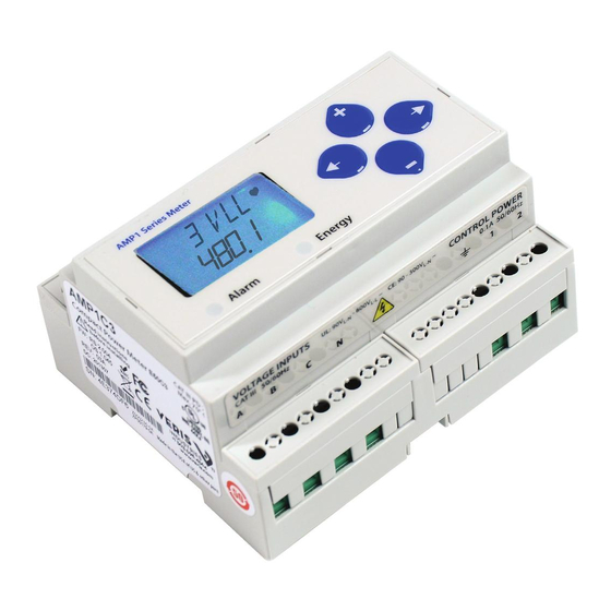
- Page 1 AMP1B1, AMP1C2, AMP1C3 Compact Power and Energy Meter for ReliaGear Lighting Panels ®...
- Page 2 A M P 1 B 1 , A M P 1C 2 , A M P 1 C 3 C o m p a c t P o w e r a n d E n e r g y M e t e r Safety FCC PART 15 Information Note: This equipment has been tested by the manufacturer and found to comply with the limits for a...
-
Page 3: Specifications
N.O., static output; (30 VAC/DC, 100 mA AND Reactive Energy max. @ 25°C, derate 0.56 mA per °C Pulse Contacts above 25°C) (AMP1B1 only) RS-485 Port (AMP1Cx) 2-wire, 1200 to 38400 baud, Modbus RTU Mechanical Weight 0.62 lb. (0.28 kg) IP Degree of Protection IP40 front displate;... -
Page 4: Product Identification
A M P 1 B 1 , A M P 1C 2 , A M P 1 C 3 C o m p a c t P o w e r a n d E n e r g y M e t e r Product Identification Product Overview Description –... -
Page 5: Wiring Diagram Symbols
Two Output Options Available overheating and permanent equipment damage. overheating and permanent equipment damage. overheating and permanent equipment damage. overheating and permanent equipment damage. AMP1B1 - Pulse AMP1Cx - RS-485 overheating and permanent equipment damage. overheating and permanent equipment damage. AMP1Cx - RS-485 AMP1B1 - Pulse •... - Page 6 A M P 1 B 1 , A M P 1C 2 , A M P 1 C 3 C o m p a c t P o w e r a n d E n e r g y M e t e r Figure 4.
-
Page 7: Control Power
A M P 1 B 1 , A M P 1 C 2 , A M P 1C 3 C o m p a c t P o w e r a n d E n e r g y M e t e r Control Power Control Power Control Power... -
Page 8: Solid State Output
(N.C.) output. One is dedicated SETUP menu. to energy (Wh), and the other to Alarm. The AMP1B1 also provides an additional N.O. reactive energy (VARh) contact. Main Menu See the Setup section for configuration information. -
Page 9: User Interface For Data Configuration
A M P 1 B 1 , A M P 1 C 2 , A M P 1C 3 C o m p a c t P o w e r a n d E n e r g y M e t e r User Interface for Data Configuration SETUP Demand... - Page 10 A M P 1 B 1 , A M P 1C 2 , A M P 1 C 3 C o m p a c t P o w e r a n d E n e r g y M e t e r Alert/Reset Information Alert/Reset Information To: ENRGY...
- Page 11 A M P 1 B 1 , A M P 1 C 2 , A M P 1C 3 C o m p a c t P o w e r a n d E n e r g y M e t e r User Interface for Setup User Interface for Setup To Setup p.
- Page 12 A M P 1 B 1 , A M P 1C 2 , A M P 1 C 3 C o m p a c t P o w e r a n d E n e r g y M e t e r To Setup p.
-
Page 13: Display Screen Diagram
Display Screen Diagram A M P 1 B 1 , A M P 1 C 2 , A M P 1C 3 C o m p a c t P o w e r a n d E n e r g y M e t e r Display Screen Diagram RS-485 Communications (AMP1Cx Only) Display Screen Diagram... -
Page 14: Quick Setup
A M P 1 B 1 , A M P 1C 2 , A M P 1 C 3 C o m p a c t P o w e r a n d E n e r g y M e t e r Quick Setup These instructions assume the meter is set to factory defaults. -
Page 15: Data Logging
A M P 1 B 1 , A M P 1 C 2 , A M P 1C 3 C o m p a c t P o w e r a n d E n e r g y M e t e r Data Logging The AMP1C3 includes a data logging feature that records 10 meter The Log Status Register has additional error flag bits that... -
Page 16: Modbus Point Map
= 0xFF if the operating system is used; status = 0x00 if the reset system is used bytes5+: ID string = “GE Industrial Solutions AMP1xx Power Meter Full Data Set” or “GE Industrial Solutions AMP1xx Power Meter - RESET SYSTEM RUNNING RS Version x.xxx”... - Page 17 A M P 1 B 1 , A M P 1 C 2 , A M P 1C 3 C o m p a c t P o w e r a n d E n e r g y M e t e r R/W NV Format Units...
- Page 18 A M P 1 B 1 , A M P 1C 2 , A M P 1 C 3 C o m p a c t P o w e r a n d E n e r g y M e t e r R/W NV Format Units...
- Page 19 A M P 1 B 1 , A M P 1 C 2 , A M P 1C 3 C o m p a c t P o w e r a n d E n e r g y M e t e r R/W NV Format Units...
- Page 20 0-32767 Power Up Counter. Output Configuration. AMP1B1, AMP1C2, and AMP1C3 units have a NO (normally open) energy contact and NC (normally closed) (Normally Open - Form A or Normally Closed - Form B) Phase Loss contact. While the relay used for the Phase Loss contact is Normally Closed (contacts are closed when the meter is not powered), closure indicates the presence of an alarm;...
- Page 21 A M P 1 B 1 , A M P 1 C 2 , A M P 1C 3 C o m p a c t P o w e r a n d E n e r g y M e t e r R/W NV Format Units...
- Page 22 A M P 1 B 1 , A M P 1C 2 , A M P 1 C 3 C o m p a c t P o w e r a n d E n e r g y M e t e r R/W NV Format Units...
-
Page 23: Installation
A M P 1 B 1 , A M P 1 C 2 , A M P 1C 3 C o m p a c t P o w e r a n d E n e r g y M e t e r Installation Supported System Types Disconnect power prior to installation. -
Page 24: Troubleshooting
ABB makes no warranty or guarantee, express or implied, that such performance will be obtained under end-use conditions. ReliaGear is a registered trademark of ABB Inc. GE is a registered trademark used under license from General Electric company. electrification.us.abb.com...