Sony FVS-1000 System Maintenance Manual
Multi resolution film scanner, multi resolution telecine, telecine processor, telecine hdtv/sdtv processing boards, telecine log data processor, telecine 16 mm film adaptor kit, telecine optical kit, telecine mounted slide kit, telecine film sound process
Hide thumbs
Also See for FVS-1000 System:
- Operation manual (44 pages) ,
- Maintenance manual (138 pages)
Table of Contents
Advertisement
Quick Links
MULTI RESOLUTION FILM SCANNER
FVS-1000 System
MULTI RESOLUTION TELECINE
FVS-T1000
TELECINE PROCESSOR
FVS-P1000
TELECINE HDTV PROCESSING BOARDS
BKFV-100/1
TELECINE SDTV PROCESSING BOARDS
BKFV-200
TELECINE LOG DATA PROCESSOR
BKFV-300
TELECINE 16 mm FILM ADAPTOR KIT
BKFV-400/1
TELECINE OPTICAL KIT
BKFV-410
TELECINE MOUNTED SLIDE KIT
BKFV-420
TELECINE FILM SOUND PROCESSOR
BKFV-500
MAINTENANCE MANUAL
1st Edition (Revised 3)
Part 1
Advertisement
Table of Contents

Related Manuals for Sony FVS-1000 System

Summary of Contents for Sony FVS-1000 System
- Page 1 MULTI RESOLUTION FILM SCANNER FVS-1000 System MULTI RESOLUTION TELECINE FVS-T1000 TELECINE PROCESSOR FVS-P1000 TELECINE HDTV PROCESSING BOARDS BKFV-100/1 TELECINE SDTV PROCESSING BOARDS BKFV-200 TELECINE LOG DATA PROCESSOR BKFV-300 TELECINE 16 mm FILM ADAPTOR KIT BKFV-400/1 TELECINE OPTICAL KIT BKFV-410 TELECINE MOUNTED SLIDE KIT...
- Page 2 ! WARNING This manual is intended for qualified service personnel only. To reduce the risk of electric shock, fire or injury, do not perform any servicing other than that contained in the operating instructions unless you are qualified to do so. Refer all servicing to qualified service personnel.
- Page 3 CAUTION Danger of explosion if battery is incorrectly replaced. WARNING When installing the unit, incorporate a readily Replace only with the same or equivalent type recommended by the manufacturer. accessible disconnect device in the fixed wiring, so that the user can turn off the power in case a fault should Dispose of used batteries according to the occur.
-
Page 5: Table Of Contents
Table of Contents Manual Structure Purpose of this manual ....................7 Related manuals ......................7 1. Installation 1-1. Overview ..................... 1-1 1-2. Unpacking and Supplied Accessories ............1-1 1-3. Environmental Conditions ................1-2 1-4. Dimensions and Weight ................1-3 1-5. Installation Space .................. - Page 6 2-8. Removing/Installing the Board ..............2-32 2-8-1. Processor Board (FVS-P1000) and BKFV-100/1, 200, 300, 500 ............. 2-32 2-8-2. SV Board .................. 2-34 2-9. Using the Extension Board ................ 2-36 2-10. Checking the Power Supply Voltage ............2-38 2-11. Function of Switches/LEDs on the Board ..........2-39 2-11-1.
- Page 7 3-4. Replacement of Periodic Replacement Part ..........3-15 3-4-1. Replacing Lamp ............... 3-15 3-4-2. Replacing the I Sprocket, C Sprocket and F Guide Roller ..3-18 3-4-3. Replacing the Filter Assembly ..........3-20 3-4-4. Replacing the IR/UV Cut Filter ..........3-22 3-4-5.
- Page 8 6. Electrical Alignment 6-1. Measuring Equipment and Tools ..............6-1 6-2. Power Supply Unit Adjustment ..............6-2 6-2-1. Power Supply Unit ..............6-2 6-2-2. DD-33Board Voltage Adjustment ..........6-5 6-3. Control Panel Adjustments ................. 6-6 6-3-1. CP-322 Board Voltage Adjustment ........... 6-6 6-4.
- Page 9 8. Block Diagrams Processor Block ...................... 8-1 Servo Block ......................8-2 Power Supply Block (For J) ................... 8-3 Power Supply Block (For UC) ................8-4 Power Supply Block (For EK) ................8-5 FVS-1000 MMP1...
-
Page 11: Manual Structure
This manual is intended for use by trained system and service engineers, and describes the service information concerning maintenance, parts replacement, mechanical adjustment, and electrical alignment. If this manual is required, please contact your local Sony Sales Office/Service Center..FVS-1000 System... - Page 12 Part number: 9-967-824-XX This manual describes the electrical parts list, semiconductor pin assignment, and boards layout. If this manual is required, please contact your local Sony Sales Office/Service Center..FVS-1000 System Maintenance Manual Part 3 Volume 2 (Available on request) Part number: 9-967-825-XX This manual describes the schematic diagrams.
-
Page 13: Installation
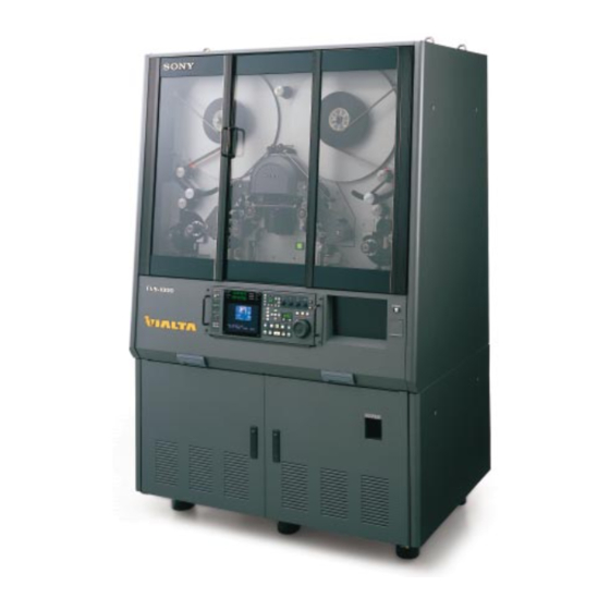
Section 1 Installation 1-1. Overview The FVS-1000 is the system to convert the video data recorded on the 35 mm or 16 mm film to the SDTV or HDTV signal and to convert the audio data to the audio signals. The FVS-1000 consists of the film transport system, processor system, imager movement table and lamp house and is mounted in the rack of which the dimensions is 1173 mm (width) x 1798 mm (height) x 780 mm (depth). -
Page 14: Environmental Conditions
1-3. Environmental Conditions 1-3. Environmental Conditions To use the FVS-1000 safely and to maintain the stable performance in the long term, keep the appropriate environmental conditions according to the followings. Especially, as for the strength of the floor where the FVS-1000 is installed, be sure to keep the specified or more strength. -
Page 15: Dimensions And Weight
1-4. Dimensions and Weight 1-5. Installation Space 1-4. Dimensions and Weight Dimensions 1173 mm (W) x 1798 mm (H) x 780 mm (D) Weight 650 kg 1173 Unit : mm 1-5. Installation Space When installing the FVS-1000, keep the following installation space taking ventilation and servicing into consideration. -
Page 16: Power Supply And Air Supply Specifications
1-6. Power Supply and Air Supply Specifications 1-6. Power Supply and Air Supply Specifications Prepare the interior wiring which is near the FVS-1000 and easy to connect with the connectors of the FVS-1000. Power supply voltage , 50/60 Hz ± 0.5 % +5 % For UC : AC 120 V _10 %... -
Page 17: Warning During Installation
1-7. Warning during Installation 1-8. Jigs and Tools 1-7. Warning during Installation Safety working . For safety, install the FVS-1000 by four or more persons. In addition, one or more of them should be trained for the installation. Keeping the parts Store the parts removed during installation, making sure that they do not damage and do not interference with work. -
Page 18: Installation Flow Chart
1-9. Installation Flow Chart 1-9. Installation Flow Chart According to the following flow chart, install the FVS-1000. As for the installation procedure, refer to Section 1-10. Start 1. Decision of the place to install 2. Installation 3. Connection of the power supply cord 4. -
Page 19: Installation Procedure
1-10. Installation Procedure 1-10. Installation Procedure 1. Decision of the place to install Confirm that the following conditions are satisfied. . Environmental conditions (Refer to “1-3. Environmental Conditions”) . Installation space (Refer to “1-5. Installation Space”) . Equipments to supply the power and air (Refer to “1-6. Power Supply and Air Supply Specifications”) 2. - Page 20 1-10. Installation Procedure (3) Place the Non-vib. mounts (L) and (R) assemblies along the relational plates as shown in the figure. While viewing the unit from the front, place the Non-vib. mounts (R) and (L) assemblies at right and left respectively. (4) Lower the unit as possible as it reaches the Non-vib.
- Page 21 1-10. Installation Procedure (9) Turn the adjuster feet with a screwdriver and lower them to the position 5 mm above the floor. Be sure to lower the adjuster feet for safety. It is recommended to connect the eye-bolts on the top plate and the ceiling with the chains as the fall preventive measure in an earthquake etc.
- Page 22 1-10. Installation Procedure Connect the safety ground. If the safety ground is not connected, there is a danger of an electrical shock. (1) Remove nine screws, then remove the rear panel. B4 x 8 Rear panel B4 x 8 (2) Remove the two screws and open the sub panel. (3) Prop up the sub panel with a support.
- Page 23 1-10. Installation Procedure (5) Remove the two screws and remove the power supply panel. (6) Remove the two screws and remove the cord stopper. (Not used when the pipe for power cable is used.) (7) Remove the two screws and remove the power supply cover. Code stopper PSW4 x 8 PSW4 x 8...
- Page 24 1-10. Installation Procedure 4. Optional unit installation Console for waveform monitor (1) Open the door and pull down the move panel assembly. (2) Remove the two screws and remove the panel. (When removing the screw on the right side of the panel, be sure to use a L-shaped wrench.) B3 x 6 CAP3 x 6...
- Page 25 1-10. Installation Procedure (4) Draw the power supply cable out of the unit and connect it to the waveform monitor. (5) Insert the waveform monitor in the waveform monitor case. Power supply cable Waveform monitor (6) Remove the eighteen screws and remove the rear panel (Middle). (7) Fix the waveform monitor to the waveform monitor case with two screws.
- Page 26 1-10. Installation Procedure Lower console (1) Open the lower door. (2) Remove the six screws and remove the front panel. Power supply cable B5 x 8 Front panel B5 x 8 (3) Draw the power supply cable out of the unit and connect it to the optional unit to be installed. (4) Fix the optional unit to the console with four screws.
- Page 27 1-10. Installation Procedure (5) Attach the blank panel with four screws. B5 x 8 Brank panel B5 x 8 5. Installation of the air blow assembly (1) Loosen the four screws of the rear panel. (2) Hang the air blow assembly on the four screws loosened in step (1) with passing the screws through the holes on the four corners of the air blow assembly.
- Page 28 1-10. Installation Procedure (4) Remove the two screws, then remove the connector cover from the rear panel. (5) Pass the connector of the air blow assembly through the hole of the connector cover, then connect it with the connector fixed to the connector support plate. (6) Fix the connector cover to the rear panel with the two screws (B3 x 6).
- Page 29 1-10. Installation Procedure (9) Set the air supply socket to the outside air supply tube, then connect the socket with the air supply porthole of the air blow assembly. Seal the air supply socket to the air supply porthole until the click can be heard. When the outside air supply tube is 1/4 inch, it is possible to use the supplied air supply socket.
- Page 30 1-10. Installation Procedure (11)Adjust the air pressure according to the following procedure. 1 Supply the outside air. 2 Pull up the regulator knob to release the lock. 3 Turn the regulator knob with pushing the red button of the electromagnetic valve. Turning the regulator knob so that the indicator of the manometer may point to the following value.
- Page 31 1-10. Installation Procedure 6. Removing the screws fixed during the transportation (Serial Nos. 10002, 10003, 10005, 10101, 10201, 10401 through 10403) This procedure is not required for the FVS-1000 other than above serial Nos. Remove the vinyl tape and two BP screws fixed during the transportation. Store the removed BP screws for transportation in the drawer of the unit.
- Page 32 1-10. Installation Procedure 8. Installation of the control panel (1) Pull out the hinges in the arrow direction. (2) Tighten the left and right lock screws to fix the hinges. Lock screw Hinge Lock screw Hinge (3) Fix the rack angle to the control panel with the supplied four screws (PSW4 x 10). (4) Place the control panel on the hinges and fix with the four screws (B5 x 10) provided.
- Page 33 1-10. Installation Procedure (6) Loosen the lock screw, then insert the control panel. Control panel 9. Installation of the OPS assembly (1) Pull the OPS cover toward you, then remove from the base plate. (2) Pass the reference pins through the holes on the OPS assembly and OPS support plate, then fix it with the supplied four screws (M3 x 6) .
- Page 34 1-10. Installation Procedure 10. Installation of the FVS-P1000 and BKFV-100/200 Front side (1) Open the lower front door of the FVS-1000. (2) Pull out the flat cable and the coaxial cable fixed to the front cover. (3) Loosen four screws (with stopper), then remove the front cover. Door Screw (with stopper)
- Page 35 1-10. Installation Procedure (4) Loosen the four screws (RK5 x 35), and remove the four washers for transportation. Store the removed washers for transportation. (5) Remove the 11 screws and remove the rear shield. (for UC/CE model only) (6) Pull out the processor assembly (5 cm). (7) Remove the connector CN3 (rear) of the processor assembly from the rear of the unit.
- Page 36 1-10. Installation Procedure (12)Insert the processor board along the guide rail. . When inserting the processor board, confirm the processor board name on the label. . Insert the processor board completely until the connector is connected. (13)Connect the flat cable with the CN6027 connector on the MY-89 board. (14)Connect the three coaxial cables with the CN402, 702 and 120 connectors on the ADC-36 board.
- Page 37 1-10. Installation Procedure (2) Insert the processor board along the guide rail. (3) Tighten the upper and lower knobs one after the other several times, then insert the connector completely until the connector is connected. Be sure to tighten the two screws one after the other. If one screw is tightened completely first, there is a possibility of damaging the connector or screw.
- Page 38 1-10. Installation Procedure 11. Turning on the power (1) Turn on the power of the external switchboard. (2) Open the lower front door of the FVS-1000, then turn on the breaker and the power switch. [Reference] Once the power is turned on, unless the power switch is turned off, ON/OFF of the power is possible by only switching the breaker with the lower door closed.
- Page 39 1-10. Installation Procedure 12. Installation of the lenses (1) Combine the 35 mm conversion lens and the master zoom lens in the following procedure. There are a standard conversion lens, an aspect conversion lens (anamophics lens, optional accessory BKFV-410) and an 8P conversion lens (optional accessory BKFV-420) in a 35 mm conversion lens. This procedure is required only when using the above mentioned several 35 mm lens.
- Page 40 1-10. Installation Procedure (2) Remove the screw a (B3 x 6), then loosen the screw b (B3 x 6), and then open the cover on the rear door of the FVS-1000 in the direction of arrow. (3) Push the “LENS EXCHANGE” button. (4) Confirm that the lamp changes from flashing to lighting, then open the rear door.
- Page 41 1-10. Installation Procedure (7) Install the lens of which the protection cap is removed to the imager, then turn the mount lever in the direction of arrow as shown in the following figure to fix. (8) Connect the lens control cable with the connector of the imager movement table assembly. Lens mount lever Imager movement table assembly Lens...
- Page 42 1-10. Installation Procedure 13. Confirmation of the operation Confirm that “SYSTEM ERROR”, “ALARM” and “WARNING” on the control panel do not light. SYSTEM ERROR ALARM Control panel WARNING SELECT SOURCE KEY INHIBIT MASTER GREEN BLUE SYSTEM ERROR REMOTE PRESET MODE MEMORY TILT ZOOM...
-
Page 43: Installation Of Optional Units
If the board name is displayed on the label in one line, the updating is required. If the board name is displayed on the label in two lines, the updating is not required. When updating is required, please contact your local Sony Sales Office/Service Center. Updating Items... - Page 44 1-11. Installation of Optional Units Tools To install the BKFV-300, the following tools are necessary. . Screw driver (+) . Screw driver (_) Installation Procedure Front side (1) Open the lower front door of the FVS-1000. (2) Pull out the flat cable and the coaxial cable fixed to the front cover. (3) Loosen four screws (with stopper), then remove the front cover.
- Page 45 1-11. Installation of Optional Units (4) Connect the flat cable with the CN6027 connector on the MY-89 board. (5) Connect the three coaxial cables with the CN402, 702 and 120 connectors on the ADC-36 board. (6) Remove the CN-1600 board inserted between the MY-89 board and CC-78 board, and insert the DP- 345 board along the guide rail.
- Page 46 1-11. Installation of Optional Units Rear side (1) Remove the five screws and remove the duct cover from the rear of the unit. (for UC/CE model only) (2) Remove the 10 screws and remove the rear shield from the processor assembly. (for UC/CE model only) (3) Loosen 2 screws (with stopper) used for the third and fourth slot from the left at the rear, and then remove the blank panel.
- Page 47 1-11. Installation of Optional Units (6) After installing all the processor boards, attach the rear shield to the processor assembly with sup- plied 10 screws. (for UC/CE model only) The processor assembly can not be pulled out from the unit when the rear shield is attached. When pulling out the processor assembly from the unit, remove the rear shield.
-
Page 48: Bkfv-400/1
1-11. Installation of Optional Units 1-11-2. BKFV-400/1 This BKFV-400/1 is the accessory kit for FVS-1000 System to enables the conversion from 16 mm film to data. The BKFV-400/1 is composed of the following blocks. . 16 mm Zoom Lens . Gate Base (16) Assembly with 16 mm Integrating Sphere . - Page 49 1-11. Installation of Optional Units (3) 16S/16T Pad Assembly Replacement The pad assembly is adjusted for every FVS-1000. Do not install the pad assembly which was adjusted with other FVS-1000. When installing the pad assembly which is using with other FVS-1000, it is necessary to perform the pad roller clearance adjustment.
- Page 50 1-11. Installation of Optional Units (4) Retainer (16) Assembly Replacement Rotate the two one-touch screws 90 degrees in counterclockwise direction by hand, and then replace the retainer (35) assembly of the FVS-1000 with retainer (16) assembly. (Refer to Section 3-2-2 “Cleaning the Retainer (35)/(16) Assembly” for details.) Guide pin One-touch screws Ritainer (35) assembly...
-
Page 51: Bkfv-410
1-11. Installation of Optional Units 1-11-3. BKFV-410 The BKFV-410 is the conversion lens which is used to convert the aspect ratio when the image informa- tion recorded on the 35 mm film is changed into data. The BKFV-410 is composed of the following lens. . -
Page 52: Bkfv-420
1-11. Installation of Optional Units 1-11-4. BKFV-420 The BKFV-420 is the kit which enables the conversion of the 35 mm 8 perforation film and slide film with the FVS-1000. The BKFV-420 is composed of the following parts. . 35 mm 8P Conversion Lens . - Page 53 1-11. Installation of Optional Units Installation (3) Install the 8P integrating sphere to the gate base (35) assembly using the two one-touch screws 1. (4) Install the gate base (35) assembly to the FVS-1000. Gate base (35) assembly Screw1 Screw1 8P integrating sphere (5) Perform the electrical adjustment After installation, perform Section 6-6-2 “35 mm Integrating Sphere Offset/Gain Adjustment”...
-
Page 54: Bkfv-500
If the board name is displayed on the label in one line, the updating is required. If the board name is displayed on the label in two lines, the updating is not required. When updating is required, please contact your local Sony Sales Office/Service Center. Updating Items... - Page 55 1-11. Installation of Optional Units Installation Flow Chart According to the following flow chart, install the BKFV-500. Start 1. Removal of the FTP panel 2. Removal of the S-AU assembly 3. Installation of the AU-278 board 4. Connection of the inter lock harness 5.
- Page 56 1-11. Installation of Optional Units Preparations (1) Set to the STANDBY OFF mode. (2) Turn OFF the power. 1. Removal of the FTP panel Remove FTP panels A, B, and D. (Refer to Section 2-7-4.) 2. Removal of the S-AU assembly (1) Remove the S-AU assembly.
- Page 57 1-11. Installation of Optional Units 3. Installation of the AU-278 board (1) Remove the two screws, and remove the harness cover. (2) Remove the four screws, and remove the duct. (UC/CE model only) Harness cover B4 x 6 B4 x 6 Duct (for UC/CE model only) B4 x 6 (3) Remove the eleven screws, and remove the rear shield.
- Page 58 1-11. Installation of Optional Units (5) Insert the AU-278 board along the guide rail, tighten the top and bottom screws of the board panel alternately, and insert the board completely until it connects to the connector. (6) Connect the sub harness (ANALOG) and sub harness (DIGITAL) to the CN700 and CN703 connec- tors.
- Page 59 1-11. Installation of Optional Units 4. Connection of the Inter Lock Harness (1) Remove the eight screws, and remove the inter lock switch cover and inter lock switch from the top panel of the FVS-1000 System. Inter lock switch (LEFT)
- Page 60 (3) Connect the red harness of the sub harness (IS2-ILG) to terminal board 4 of the right switch, and the white harness to terminal board 3 of the left switch, and install the inter lock switch to the top panel of the FVS-1000 System using the four screws. Inter lock switch...
- Page 61 1-11. Installation of Optional Units 5. Installation of the Analog Audio Assembly (1) Loosen the setscrew, and remove the handle from the analog audio assembly. (2) As the laser slit lens is optional, install the analog audio assembly,and after determing the position using the tool, tighten the two setscrews.
- Page 62 1-11. Installation of Optional Units (3) Install the compression spring, spacer, guide roller, and two bearings as shown in following figure. (4) Install the bearing retainer. Guide roller Bearing Bearing retainer Compression spring Spacer Bearing Setscrew 1-50 FVS-1000 MMP1...
- Page 63 1-11. Installation of Optional Units (5) Install the analog audio assembly to the FVS-1000 System using the four screws. (6) Install the S guide installation panel using the two screws. (7) Connect the sub harness (PRE-AL) to the CN1 connector of the PRE-46 board.
- Page 64 1-11. Installation of Optional Units 6. Guide Roller Height Adjustment Height adjustment of GR3 adjustment (1) Remove the FTP panel F. (Refer to Section 2-7-4.) (2) Install the reference base assembly to the FTP panel F fixing support on the base plate using the two screws.
- Page 65 1-11. Installation of Optional Units Height adjustment of GR4, GR5 adjustment (4) Remove the gate base assembly. (Refer to Section 3-2-1.) (5) Install the 35GR reference base assembly. (Refer to Section 4-7.) (6) While pressing the 35GR height gauge gently against the 35GR reference base assembly, move it in the arrow direction, and check that the top surface of the 35GR height gauge touches the upper flange film support of the guide roller.
- Page 66 1-11. Installation of Optional Units 7. Adjustment Refer Sections 5-1 and 5-2 and adjust. 8. Installation of the FTP Panel and S Electrode of Ionizer (1) Install FTP panels A and B. (Refer to Section 2-7-4.) (2) Install the S electrode ionizer. (Refer to Section 4-1.) (It is not necessary to remove this pant for the serial number 10701 and later.) (3) Install the FTP panel D.
- Page 67 1-11. Installation of Optional Units 10. Installation of the Caution Label Paste the caution label at the position indicated in the figure. 5 mm 15 mm FTP panel A 15 mm Caution label (3-633-478-01) Caution label (3-633-478-01) 5 mm Caution label (3-633-478-01) Laser class 1 label Caution label...
-
Page 69: Service Overview
Section 2 Service Overview 2-1. Operating Conditions 2-3. Location of Main Parts . Operating temperature : 10 dC to 35 dC 2-3-1. Location of Main Blocks (Recommended temperature range: 20 dC to 25 dC) . Operating humidity : 20 % to 90 % (no condensation) . -
Page 70: Location Of Boards
2-3. Location of Main Parts 2-3-2. Location of Boards FVS-T1000 (Front panel) Front side FVS-1000 MMP1... - Page 71 2-3. Location of Main Parts Name of board Number SW-989 board CN-1745 board SE-535 board SE-536 board SW-1004 board PS lamp assembly — CN-1849 board Power supply assembly — RE-136 board RE-137 board LE-186 board Base plate assembly — CN-1622 board CN-1623 board SE-448 board SE-449 board...
- Page 72 2-3. Location of Main Parts FVS-T1000 (Rear panel) Rear side FVS-1000 MMP1...
- Page 73 2-3. Location of Main Parts Name of board Number RM-174 board CN-1763 board CN-1835 board DD-33 board SV-186 board SV-191 board SV-192 board SE-520 board VS-60 board ES-30 board CN-2142 board FVS-1000 MMP1...
- Page 74 2-3. Location of Main Parts Imager movement table assembly Right side Rear side Name of board Number Name of board Number Imager movement table assembly — Imager — DR-384 board DU-1 board CN-1766 board PA-173 board SE-501 board DR-376 board CN-1746 board NR-66 board SW-13 board...
- Page 75 2-3. Location of Main Parts Lamp house assembly Right side Name of board Number SE-518 board LC-35 board CN-1833 board SE-519 board PD-91 board CN-1849 board Control panel assembly Rear side Right side Name of board Number CN-1610 board CN-1612 board CN-1611 board CN-1871 board CN-1626 board...
- Page 76 2-3. Location of Main Parts FVS-P1000 (processor) Location of the boards on the processor block 1 2 3 4 5 6 7 8 9 !; !' !, !. @/ @- @= @[ Upper View OPTION BOARD FVS-P1000 FVS-T1000 BKFV-100 BKFV-200 BKFV-300 BKFV-500 TX-67...
-
Page 77: Location Of Main Mechanical Parts
2-3. Location of Main Parts 2-3-3. Location of Main Mechanical Parts @/ @- Number Name of part Number Name of part Guide roller 11 Lamp house S side reel T side intermittent sprocket E guide roller (S) T side continuous sprocket F guide roller (SI) Guide roller 7 Guide roller 1... -
Page 78: Location Of Sensors
2-3. Location of Main Parts 2-3-4. Location of Sensors Front side 2-10 FVS-1000 MMP1... - Page 79 2-3. Location of Main Parts Rear side Sensor Function Front internal lock SW The power is turned on by closing the front door. S side tension regulator potential meter This meter detects the rotation angle of the S side tension regulator arm. S tension regulator position sensor This sensor detects load and unload position of S tension regulator.
-
Page 80: Film Threading
2-4. Film Threading 2-4. Film Threading This unit is designed so that the film cannot be driven unless the front door is closed due to the danger of touching the film driven with the hand, etc. For this reason, stop running when removing the film, and open the front door after standby off. . -
Page 81: Connecting Connector/Cable
2-5. Connecting Connector/Cable 2-5. Connecting Connector/Cable When connecting the cables with the connector on the connector panel, use the following connector/cable or equivalent. Indication on the connector panel of FVS-1000 Name of connector/cable Part number HD30 IN/OUT BNC, 75 Z, Male —... -
Page 82: Input And Output Signals Of Connectors
2-6. Input and Output Signals of Connectors 2-6. Input and Output Signals of Connectors Rear side of FVS-P1000 HD IN HD OUT HD IN HD OUT SD IN SD OUT SD IN SD OUT LINK A LINK A LINK LINK LINK LINK HD 30... - Page 83 2-6. Input and Output Signals of Connectors Indication on the connector panel Connector type and input/output signals of FVS-1000 HD30 IN/OUT : HD25 IN/OUT : 0.6 V p-p, 75 Z, TRI SYNC HD24 IN/OUT : 525 IN/OUT : 625/50 IN/OUT : 0.286 V p-p, 75 Z, Black burst HD IN IN :...
- Page 84 2-6. Input and Output Signals of Connectors AUX 1/2 : (D-sub 9-pin, Female) AUX 5 : AATON (D-sub 9-pin, Female) REMOTE 1/2/3 : RS-422A (D-sub 9-pin, Female) - EXT VIEW - - EXT VIEW - Pin No. Signal name Contents Pin No.
- Page 85 2-6. Input and Output Signals of Connectors AUX : (6-pin, Male) PANEL : RS-422 (8-pin, Female) - EXT VIEW - - EXT VIEW - Pin No. Signal name Contents Pin No. Signal name Contents — FRM PULSE Frame Pulse Output —...
-
Page 86: Removing/Installing The Cabinet And Ftp Panels
2-7. Removing/Installing the Cabinet and FTP Panels 2-7. Removing/Installing the Cabinet and FTP Panels 2-7-1. Removing/Installing the Side Panel and Top Panel Removing/Installing the Side Panel (Top) Removal 1. Remove the two screws at side and one screw at top of the left side panel (top). 2. - Page 87 2-7. Removing/Installing the Cabinet and FTP Panels PSW x 8 PSW4 x 8 Top plate PSW4 x 8 PSW x 8 PSW4 x 8 Left side panel (Top) Right side panel (Top) PSW4 x 8 PSW4 x 8 PSW4 x 8 PSW4 x 8 PSW4 x 8 Left side panel...
-
Page 88: Removing/Installing The Rear Panel
2-7. Removing/Installing the Cabinet and FTP Panels 2-7-2. Removing/Installing the Rear Panel Removing/Installing the Rear Panel (Top) Removal 1. Remove the 13 screws and remove the rear panel (top). Installation 2. Perform the reverse order of the removal procedure. Removing/Installing the Rear Panel (Middle) Removal 1. - Page 89 2-7. Removing/Installing the Cabinet and FTP Panels Rear panel (Top) B4 x 8 Rear panel (Middle) B4 x 8 Rear panel (Bottom , right) B4 x 8 Rear panel (Bottom , left) B4 x 8 2-21 FVS-1000 MMP1...
-
Page 90: Removing/Installing The Door
2-7. Removing/Installing the Cabinet and FTP Panels 2-7-3. Removing/Installing the Door Removal 1. Pull out the door. 2. Remove the one screw of the hinges shown in the figure. Installation 3. Perform the reverse order of the removal procedure. Supplied screw or Hinge B4 x 10 Door... -
Page 91: Removing/Installing The Ftp Panel
2-7. Removing/Installing the Cabinet and FTP Panels 2-7-4. Removing/Installing the FTP Panel Layout of FTP panels FTP panel A FTP panel F FTP panel B FTP panel C FTP panel D FTP panel E 2-23 FVS-1000 MMP1... - Page 92 2-7. Removing/Installing the Cabinet and FTP Panels Removing/Installing the FTP Panel A Removal 1. Rotate the knob assembly in the counterclockwise direction and remove it. (Both S, T) 2. Remove the four screws, and remove the core stopper (B). (Both S, T) 3.
- Page 93 2-7. Removing/Installing the Cabinet and FTP Panels 5. Remove the guard stopper assembly. (Both S, T) 6. Remove the drive cover (2). (Both S,T) 7. Remove the six fixing screwsl, and remove the FTP panel A. FTP panel A B4 x 8 Drive cover(2) B3 x 6 Guard stopper assembly...
- Page 94 2-7. Removing/Installing the Cabinet and FTP Panels Removing/Installing the FTP Panel B Removal 1. Rotate the knob assembly in the counterclockwise direction and remove it. (S side only) (Refer to “Removing/Installing the FTP Panel A”.) 2. Remove the four screws, and remove the core stopper (B). (S side only) (Refer to “Removing/ Installing the FTP Panel A”.) 3.
- Page 95 2-7. Removing/Installing the Cabinet and FTP Panels Removing/Installing the FTP Panel C Removal 1. Rotate the knob assembly in the counterclockwise direction and remove it. (T side only) (Refer to “Removing/Installing the FTP Panel A”.) 2. Remove the four screws, and remove the core stopper (B). (T side only) (Refer to “Removing/ Installing the FTP Panel A”.) 3.
- Page 96 2-7. Removing/Installing the Cabinet and FTP Panels Removing/Installing the FTP Panel D Removal 1. Pull down the move panel assembly. 2. Remove the four screws, and remove the FTP panel D. FTP panel D B4 x 8 B4 x 8 Move panel assembly Installation 3.
- Page 97 2-7. Removing/Installing the Cabinet and FTP Panels Removing/Installing the FTP Panel E Removal 1. Pull down the move panel assembly. 2. Disconnect the two harnesses connected to the board of the move panel assembly. 3. Disconnect the two harnesses above fixed to the frame and FTP panel E from the clamper. 4.
- Page 98 2-7. Removing/Installing the Cabinet and FTP Panels Removing/Installing the FTP Panel F Removal 1. Rotate the knob assembly in the counterclockwise direction and remove it. (Both S, T) (Refer to “Removing/Installing the FTP Panel A”.) 2. Remove the four screws, and remove the core stopper (B). (Both S, T) (Refer to “Removing/Installing the FTP Panel A”.) 3.
- Page 99 2-7. Removing/Installing the Cabinet and FTP Panels 10. Remove the 12 screws, and remove the FTP panel F. FTP panel F B4 x 8 B4 x 8 B4 x 8 B4 x 8 B4 x 8 B4 x 8 B4 x 8 Installation 11.
-
Page 100: Removing/Installing The Board
2-8. Removing/Installing the Board 2-8. Removing/Installing the Board 2-8-1. Processor Board (FVS-P1000) and BKFV-100/1, 200, 300, 500 Front side Removal 1. Open the door at the bottom of the unit. 2. Loosen the four screws (with stopper), and remove the front cover. 3. - Page 101 2-8. Removing/Installing the Board Rear view Removal 1. Remove the 11 screws and remove the rear shield. (for UC/CE model only) 2. Loosen the two screws (with stopper) at the top and bottom of the board panel alternately. 3. Pull out the processor board from the guide rail. Screws Screws Screws (with stopper)
-
Page 102: Board
2-8. Removing/Installing the Board 2-8-2. SV Board Removal 1. Remove the rear panel (top). (Refer to Section 2-7-2.) 2. Remove the two screws fixing the SV board. 3. Pull out the SV board from the guide rail. 4. Remove the harness connected to the SV board. Positioning hole Guide rail Positioning pin... - Page 103 2-8. Removing/Installing the Board Installation 5. Perform the reverse of steps 1 to 4 of the removal procedure. . Connect the harnesses to the corresponding connectors (connector No.). (Refer to the following diagram.) . Push in each board until the positioning pin goes inside the positioning hole. SV-186 board Side A CN100 CN33(NC)
-
Page 104: Using The Extension Board
2-9. Using the Extension Board 2-9. Using the Extension Board The extension board is provided with the FVS-P1000 for checking and adjusting the processor board. . Extension board (EX-632): A-8320-763-A For extending the board in front of the processor . Extension board (EX-670): A-8320-764-A For extending the board at the rear of the processor Extending the Front Side Board 1. - Page 105 2-9. Using the Extension Board Extending the Rear Side Board 1. Remove the 11 screws and remove the rear shield. (for UC/CE model only) (Refer to Section 2-8-1.) 2. Loosen the screws (with stopper) at the top and bottom of the board panel alternately. 3.
-
Page 106: Checking The Power Supply Voltage
2-10. Checking the Power Supply Voltage 2-10. Checking the Power Supply Voltage 1. Check the VS-60 board from the slit of the rear panel. 2. Confirm that the harness is connected with the connector of the appropriate voltage on the VS-60 board. -
Page 107: Function Of Switches/Leds On The Board
2-11. Function of Switches/LEDs on the Board 2-11. Function of Switches/LEDs on the Board 2-11-1. ADC-36 Board S5301 S5101 S5100 S5106 S5105 S1500 S5300 S5102 S5103 S5104 ADC-36 BOARD (A SIDE) Switches Do not change the setting of the switch described as “Factory use only” Ref.No. - Page 108 2-11. Function of Switches/LEDs on the Board 2-11-2. CC-78 Board S8000 S7001 S7000 S8001 S6000 S7500 S6500 S6002 S6001 CC-78 BOARD (A SIDE) Switches Do not change the setting of the switch described as “Factory use only” Ref.No. Address Name Function Factory setting S7001...
-
Page 109: Cn-1600 Board
2-11. Function of Switches/LEDs on the Board 2-11. Function of Switches/LEDs on the Board 2-11-3. CN-1600 Board S201 S202 CN-1600 BOARD (A SIDE) Switches Do not change the setting of the switch described as “Factory use only” Ref.No. Address Name Function Factory setting S201... -
Page 110: Board
2-11. Function of Switches/LEDs on the Board 2-11-4. CP-322 Board S301 D301 S100 S300 CP-322 BOARD (A SIDE) Switches Do not change the setting of the switch described as “Factory use only” Ref.No. Address Name Function Factory setting S100 (F-4) S100-1 to 6,8 : Factory use only All bits OFF (7bits) S100-7 :... -
Page 111: Board
2-11. Function of Switches/LEDs on the Board 2-11-5. DCP-20 Board S2700 S2701 S2500 S2600 D2600 D2601 S300 S900 DCP-20 BOARD (A SIDE) Switches Do not change the setting of the switch described as “Factory use only” Ref.No. Address Name Function Factory setting S900 (P-8) -
Page 112: Board
2-11. Function of Switches/LEDs on the Board 2-11-6. DHP-10 Board S2100 S2001 S2000 D1600 DHP-10 BOARD (A SIDE) Switches Do not change the setting of the switch described as “Factory use only” Ref.No. Address Name Function Factory setting S2100 (N-3) S2100-1 : Factory use only S2100-2 : Internel test SG 1 2 3 4 5 6 7 8... -
Page 113: Board
2-11. Function of Switches/LEDs on the Board 2-11-7. DSP-81 Board S1501 S1700 S1701 S1500 DSP-81 BOARD (A SIDE) Switches Do not change the setting of the switch described as “Factory use only” Ref.No. Address Name Function Factory setting S1700 (E-4) HIB Enable/Disable select S1700-1 : HIB Enable/Disable 1 2 3 4 5 6 7 8... - Page 114 2-11. Function of Switches/LEDs on the Board Ref.No. Address Name Function Factory setting S1701 (E-4) TSG signal selector TSG signal select (When S1700-8 is ON, V or H signals) 0 : Vertical 100% color bars 1 : V sweep for Progressive (Y/Cb/Cr) 2 : V sweep for Interlace (Y/Cb/Cr) 3 : V ramp (Y/Cb/Cr) 4 : Vertical 75% color bars...
-
Page 115: Board
2-11. Function of Switches/LEDs on the Board 2-11-8. EN-137 Board S1100 S1101 S1200 S1201 EN-137 BOARD (A SIDE) Switches Do not change the setting of the switch described as “Factory use only” Ref.No. Address Name Function Factory setting S1101 (N-6) S1101-1 : All bits OFF S1101-2 :... -
Page 116: Board
2-11. Function of Switches/LEDs on the Board 2-11-9. IF-693 Board IF-693 BOARD (A SIDE) Switches Ref.No. Address Name Function Factory setting (C-4) Factory use only All bits OFF (8bits) 2-48 FVS-1000 MMP1... -
Page 117: Board
2-11. Function of Switches/LEDs on the Board 2-11-10. LC-35 Board S101 S103 S102 S104 S501 S400 S502 D501 LC-35 BOARD (A SIDE) Switches Do not change the setting of the switch described as “Factory use only” Ref.No. Address Name Function Factory setting S103 (E-1) -
Page 118: Board
2-11. Function of Switches/LEDs on the Board 2-11-11. MY-89 Board S7001 S6009 S6010 S6000 S4000 S6004 S6003 S7000 S6001 MY-89 BOARD (A SIDE) Switches Do not change the setting of the switch described as “Factory use only” Ref.No. Address Name Function Factory setting S7000... - Page 119 2-11. Function of Switches/LEDs on the Board 2-11-12. RX-45 Board D800 S800 S801 RX-45 BOARD (A SIDE) Switches Ref.No. Address Name Function Factory setting S800 (H-3) SDI-VCO adjustment SDI-VCO frequency adjustment S800-1 : Free run frequency adjustment ON: Free run frequency adjustment at 625/48 OFF: Free run frequency adjustment at 525/59.94 &...
-
Page 120: Board
2-11. Function of Switches/LEDs on the Board 2-11-13. SV-191 Board S101 S100 S400 SV-191 BOARD (A SIDE) Switches Do not change the setting of the switch described as “Factory use only” Ref.No. Address Name Function Factory setting S400 (H-10) SV CPU (reel,...etc) Sets the operating mode of servo CPU S400-1 : Factory use only S400-2 : Factory use only... -
Page 121: Board
2-11. Function of Switches/LEDs on the Board 2-11-14. SY-256 Board D2400 D2500 D2901 S500 D4808 D4809 D4811 D4805 D4002 D4000 D4003 D4001 D4008 D4004 D4012 D4006 D4804 D4009 D4005 D4013 D4007 D4014 D4010 D4015 D4011 D4020 D4016 D4021 D4017 D4022 D4018 D4803 D4023... - Page 122 2-11. Function of Switches/LEDs on the Board LEDs Ref.No. Address Color Name Function Normal condition D1003 (P-7) Green Light on reset D1002 (P-8) Green Flash by Reference Frame synchronously. Normaly flash D1001 (P-8) Green Flash by Film Frame synchronously. Normaly flash D1000 (P-8) Green...
-
Page 123: Board
2-11. Function of Switches/LEDs on the Board 2-11-15. TX-67 Board D1100 S1101 S1100 TX-67 BOARD (A SIDE) Switches Ref.No. Address Name Function Factory setting S1100 (H-5) SDI-VCO adjustment SDI-VCO frequency adjustment S1100-1 : Free run frequency adjustment ON: Free run frequency adjustment at 625/48 OFF: Free run frequency adjustment at 525/59.94 &... -
Page 124: Board
2-11. Function of Switches/LEDs on the Board 2-11-16. VE-42 Board S1101 S1201 S1100 S1200 VE-42 BOARD (A SIDE) Switches Do not change the setting of the switch described as “Factory use only” Ref.No. Address Name Function Factory setting S1101 (N-3) Factory use only All bits OFF S1200... -
Page 125: Board (Bkfv-300)
2-11. Function of Switches/LEDs on the Board 2-11-17. DP-345 Board (BKFV-300) S3702 S3500 S3900 S3701 S3700 S3600 DP-345 BOARD (A SIDE) Switches Do not change the setting of the switch described as “Factory use only”. Ref.No. Address Name Function Factory setting S3500 (R-8) DP reset switch... - Page 126 2-11. Function of Switches/LEDs on the Board 2-11-18. DIF-120 Board (BKFV-300) S201 S200 S1000 DIF-120 BOARD (A SIDE) Switches Do not change the setting of the switch described as “Factory use only”. Ref.No. Address Name Function Factory setting S201 (M-1) 1 to 2: Factory use only All bits OFF S1000...
-
Page 127: Cn-2243 Board (Bkfv-300)
2-11. Function of Switches/LEDs on the Board 2-11-19. CN-2243 Board (BKFV-300) S400 S131 S130 CN-2243 BOARD (A SIDE) Switches Do not change the setting of the switch described as “Factory use only”. Ref.No. Address Name Function Factory setting S131 (N-7) CN2243 reset switch Initialize the CN board —... -
Page 128: Board (Bkfv-500)
2-11. Function of Switches/LEDs on the Board 2-11-20. AU-278 Board (BKFV-500) D800 S801 D305 D304 S900 D303 D302 D104 D801 D300 S800 AU-278 BOARD (A SIDE) Switches Do not change the setting of the switch described as “Factory use only”. Ref.No. - Page 129 2-11. Function of Switches/LEDs on the Board LEDs Ref.No. Address Color Name Function Normal condition D300 (F-1) PLL LOCK ON: LOCK, OFF: UNLOCK D302 (E-3) VCO control Blinks D303 (E-3) Green VCO control Blinks D304 (E-4) VCO control Blinks D305 (E-4) VCO PLAY ON: PLAY, OFF: STOP...
-
Page 131: Periodic Check And Maintenance
Section3 Periodic Check and Maintenance Perform the periodic checks and maintenance in order to ensure correct function and performance and also to extend the life of the film. 3-1. Periodic Inspection List 3-1-1. Telecine Main Unit (FVS-T1000) The time shown below is not the warranted time of the part. Use the following time as reference to plan the maintenance and inspection. -
Page 132: Film Sound Processor (Bkfv-500)
3-1. Periodic Inspection List 3-2. Cleaning the Running System 3-1-2. Film Sound Processor (BKFV-500) C : Inspection and cleaning R : Replacement Inspection item Inspection time (h) (Laser lighting time) Replaced part Amount Referring 1000 2000 3000 4000 Part number page Laser source unit R : every 20000 h... -
Page 133: Cleaning The Gate Base (35) / (16) Assembly
3-2. Cleaning the Running System 3-2-1. Cleaning the Gate Base (35) / (16) 4. Remove the adherence with air etc. Assembly 5. Clean the top of the gate with the cleaning cloth to which the cleaning fluid is applied. 6. Wipe the cleaned surface with a dry cloth two or three Removal times. -
Page 134: Cleaning The Retainer (35) / (16) Assembly
3-2. Cleaning the Running System 3-2-2. Cleaning the Retainer (35) / (16) 5. Remove the adherence with air etc. Assembly 6. Clean the portion contacting the gate on the GND terminals, the portion contacting the film on the film pad and film guides with a cleaning cloth to which the Removal cleaning fluid is applied. -
Page 135: Cleaning The Guide Roller
3-2. Cleaning the Running System 3-2-3. Cleaning the Guide Roller Clean the guides shown in the figure using a cleaning cloth moistened with cleaning liquid. E guide roller E guide roller PAD roller PAD roller GR10 Guide roller Guide roller (S tension regulator) (T tension regulator) F guide roller... -
Page 136: Cleaning The Pt Roller
3-2. Cleaning the Running System 3-2-4. Cleaning the PT Roller Cleaning with adhesive tape Removal/Reinstallation Washing with water 1. Remove the whole PTR retainer assembly with the PT Removal/Reinstallation rollers installed. 1. Remove the PT rollers from the holder roller assem- 2. -
Page 137: Cleaning The Static Electricity Eliminator
3-2. Cleaning the Running System 3-2-5. Cleaning the Static Electricity 3-2-6. Cleaning the Audio Drums (Top) and Eliminator (Bottom) (BKFV-500) 1. Clean off the dusts on the white wires of the static 1. Remove the audio cover. (Refer to Section 4-1.) electricity eliminator of S and T sides using soft cloth 2. -
Page 138: Cleaning The Optical System
3-3. Cleaning the Optical System 3-3. Cleaning the Optical System Clean the following to maintain the optimum light amount. . Lens assembly . OPS assembly . FLC assembly (Integrating sphere, F-FLC, HMF, lens, and IR/UV cut filter) To maintain the performance of the FLC assembly, it is kept at optimum temperature. Clean the follow- ing to ensure the cooling effects. -
Page 139: Cleaning The Lens Assembly
3-3. Cleaning the Optical System 3-3-1. Cleaning the Lens Assembly 3-3-2. Cleaning the OPS Assembly 1. Remove the lens assembly. (Refer to Section 1-10, 1. Remove the gate base (35) assembly. step 12.) (Refer to Section 3-2-1.) 2. Blow off the dusts on the lens surface using the air 2. -
Page 140: Cleaning The Flc Assembly
3-3. Cleaning the Optical System 3-3-3. Cleaning the FLC Assembly F-FLC 1. Remove the gate base (35) assembly. (Refer to Section 3-2-1.) Do not push the glass side of the F-FLC with force or hit it 2. Remove the integrater assembly from the gate base with a hard object as this may cause the performance of the (35) assembly. - Page 141 3-3. Cleaning the Optical System Lens and IR/UV Cut Filter (1) Remove the two screws, and remove the filter retainer. (1) Blow off the dusts on the lens and IR/UV cut filter (IR/UV cut filter.) using the air blower for optical use. (2) Remove the four screws, and remove the lens holder (2) For stubborn dusts which cannot be removed using the and lamp cover (front).
- Page 142 3-3. Cleaning the Optical System FLC Fan Entrance and Heat Sink Lamp Exit and Heat Sink (1) Remove the three screws, and remove the lamp base (1) Vacuum the dusts on the lamp exit and heat sink using stay (L). a vacuum cleaner, etc.
- Page 143 3-3. Cleaning the Optical System Lamp Fan Lamp House Cover (1) Remove the two screws, and remove the lamp cover (1) Vacuum the dusts on the lamp house cover using a (rear). vacuum cleaner, etc. (2) Vacuum the dusts on the fan using a vacuum cleaner, (2) Wipe off the dirt on the lamp house cover using a dry etc.
-
Page 144: Cleaning Of The Laser Slit Lens
3-3. Cleaning the Optical System 3-3-4. Cleaning of the Laser Slit Lens, 35 mm/16 mm Head Assemblies (BKFV-500) 1. Remove the audio cover. (Refer to Section 4-1.) 2. Clean the laser slit lens, 35 mm head assembly and 16 mm head assembly using the cotton swab moistened with cleaning liquid for optical use. -
Page 145: Replacement Of Periodic Replacement Part
3-4. Replacement of Periodic Replacement Part 3-4. Replacement of Periodic Removal Replacement Part 1. Removing the gate base assembly 3-4-1. Replacing Lamp Remove the gate base assembly. (Refer to Section 3-2-1.) When the lamp does not light, replace the lamp according to the following procedures. - Page 146 3-4. Replacement of Periodic Replacement Part (2) Pull out the lamp house assembly in the direction of (2) Loosen the four screws (with stopper), and remove the the arrow until the rail is locked. lamp cover. (3) Pull up the used lamp cased in the blue plastic box. Lamp house assembly Lamp Rail...
- Page 147 3-4. Replacement of Periodic Replacement Part Before scrapping the used lamp Installation Nip the chip off at the rear side of the lamp with nippers etc., then make V shaped cutting on it with turning nippers Be careful not to damage the glass surface of the lamp or in the directions of arrow until you hear the sound of gas’s not to make it dirty.
-
Page 148: Replacing The I Sprocket, C Sprocket And F Guide Roller
3-4. Replacement of Periodic Replacement Part 3-4-2. Replacing the I Sprocket, C Sprocket 2. Removing the sprocket and F Guide Roller (1) Remove the motor GND plug on the sprocket. (2) Remove the washer CAP. This section describes the replacement procedures of the I (3) Loosen the two setscrews on the side of the sprocket sprocket, C sprocket and F guide roller. - Page 149 3-4. Replacement of Periodic Replacement Part 4. Installing the F guide roller C sprocket (S side) (1) Install the F guide roller so that the largest diameter of I sprocket (S side) the guide is positioned down. (2) Install the sprocket. (Refer to step 3.) (3) Tighten the F-GR flange to the shaft tentatively.
-
Page 150: Replacing The Filter Assembly
3-4. Replacement of Periodic Replacement Part 3-4-3. Replacing the Filter Assembly 6. Confirming the F guide roller height (1) Check the clearance A between the sprocket and F-GR flange meets the following specifications using the Preparations thickness gauge. 1. Turn the unit into the STANDBY OFF mode. 2. - Page 151 3-4. Replacement of Periodic Replacement Part 4. Removing the lamp house front panel Installation assembly Remove the six screws, and remove the lamp house front 6. Installing the lamp house front panel assembly panel assembly. Install the lamp house front panel assembly with six B4 x 14 B4 x 14 screws.
-
Page 152: Replacing The Ir/Uv Cut Filter
3-4. Replacement of Periodic Replacement Part 3-4-4. Replacing the IR/UV Cut Filter Installation Preparation 4. Installing the IR/UV cut filter Turn off the AC power supply which supplies the power to (1) Install a new IR/UV cut filter. [Reference] [Reference] [Reference] [Reference] [Reference]... - Page 153 3-4. Replacement of Periodic Replacement Part 3-4-5. Replacing the P Roller 35 Assembly/P Removal Roller 16 Assembly 1. Removing the pas assembly This section describes the replacement procedures of the P Rotate the two one-touch screws of the pad assembly by roller 35 assembly of the S side pad assembly.
- Page 154 3-4. Replacement of Periodic Replacement Part 2. Removing the P roller 35 assembly 5. Installing the pad roller clearance adjustment tool Push the lock plate, and turn the pad arm as shown in the figure. Hook the pad roller clearance adjustment tool to the Remove the P roller retainers, and remove the P roller 35 sprocket as shown in the figure.
- Page 155 3-4. Replacement of Periodic Replacement Part 7. Adjusting the pad roller clearance (1) Rotate the pad roller shaft in the arrow direction using the flatblade screwdriver. Then temporarily tighten the setscrews with all pad rollers touching the roller clearance adjustment tool (film). Pad roller clearance adjustment tool (Film) Pad roller shafts...
- Page 156 3-4. Replacement of Periodic Replacement Part 3-4-6. Replacing the Guide Roller 35/16 and Removal Ball Bearing 1. Removing the guide roller and ball bearing The twelve guide roller 35/16 are used in this unit, and 24 (1) Remove the bearing retainer of the upper portion of ball bearings are used to the upper and lower sides of these the guide roller.
-
Page 157: Replacing The Film Guide (G) Assembly
3-4. Replacement of Periodic Replacement Part 3-4-7. Replacing the Film Guide (G) (2) Remove the two E-rings (E-2.3), and remove the film Assembly guide (G) assemblies. The two film guide (G) assemblies are installed in the gate At this time, the compression springs are removed base (35) assembly, and one film guide (G) assembly is together. - Page 158 3-4. Replacement of Periodic Replacement Part 3-4-8. Replacing the E Guide Roller (35)/(16) 3. Removing the E guide roller (35) assembly Assembly (1) Loosen the two precision screws fully, and pull out the E guide shaft 35, and then remove the E guide roller The two E guide roller (35) assemblies and two (16) (35) assembly.
- Page 159 3-4. Replacement of Periodic Replacement Part 5. Checking the E guide height (5) While keeping the state of step (3), check the clearance (1) Clean the gate base (35) assembly. between the E guide flange and E guide stay 35 using (Refer to Section 3-2-1.) the thickness gauge.
- Page 160 3-4. Replacement of Periodic Replacement Part 6. Adjusting the E guide height (3) Check the specifications of (4) and (5) of step5 again. (1) Loosen the two screws shown in the figure to move the (4) After checking the specifications, apply the locking E guide stay 35 smoothly.
-
Page 161: Replacing The Film Pad (35)/(16) Assemblies
3-4. Replacement of Periodic Replacement Part 3-4-9. Replacing the Film Pad (35)/(16) 2. Removing the film pad (35) assembly Assemblies (1) Remove the four screws, and remove the filter case. (2) Remove the two E-rings (E-1.5) shown in the figure, The film pad (35) assembly and film pad (16) assembly are and remove the film pad (35) assembly. -
Page 162: Replacing The Filter Regulator And Mist Separator Element
3-4. Replacement of Periodic Replacement Part 3-4-10. Replacing the Filter Regulator and 2. Removing the case assembly Mist Separator Element (1) Remove the drain assembly. (2) Rotate the case assembly of the filter regulator in the arrow direction to remove. When replacing the filter element, turn off the power and disconnect the air first. -
Page 163: Replacing The Laser Source Unit
3-4. Replacement of Periodic Replacement Part 3-3-11. Replacing the Laser Source Unit 5. Adjusting the air pressure (1) Supply the external air. Preparations 1. Put the unit into STANDBY OFF mode. Regulator knob 2. Turn off the AC power supply which supplies the power to the FVS-1000. -
Page 164: Replacing The Audio Drum (Top) And (Bottom)
3-4. Replacement of Periodic Replacement Part 3-4-12. Replacing the Audio Drum (Top) and 5. Removing the laser source unit (Bottom) Loosen the setscrew, and remove the laser source unit. Preparations 1. Put the unit into STANDBY OFF mode. PRE-46 board 2. - Page 165 3-4. Replacement of Periodic Replacement Part 5. Removing the 35 mm head assembly 7. Removing the 16 mm head assembly Remove the audio head flange, and loosen the two set- (1) Loosen a setscrew, and remove the audio head height screws, and then remove the 35 mm head assembly.
- Page 166 3-4. Replacement of Periodic Replacement Part Installation 9. Installing the audio drum (bottom) Install the audio drum (bottom). 10. Installing the 16 mm head assembly Install the 16 mm head assembly in the reverse order of removal. 11. Installing the audio drum (top) Install the audio drum (top) in the reverse order of remov- 12.
-
Page 167: Replacement Of Main Parts
Section 4 Replacement of Main Parts 4-1. General Information on Parts Replacement Tightening Torque of Screws Screws must be tightened with the following tightening torque. Hexagonal screws with hole (M3) : 98 x 10 N.m (10.0 kgf.cm) (M4) : 245 x 10 Hexagonal screws with hole N.m (25.0 kgf.cm) Hexagonal screws with hole... -
Page 168: Replacing The Pad Assembly
4-2. Replacing the Pad Assembly 4-2. Replacing the Pad Assembly Notes The pad assembly is adjusted for each unit. Do not install to other FVS-1000s. When the film is run without adjusting, the film may damage. To install to other FVS-1000, there is a need to adjust the clearance with the sprock- 35/16S Pad Assembly Removal 1. - Page 169 4-2. Replacing the Pad Assembly 35/16T Pad Assembly Removal 1. Removing the pad assembly Pad positioning shaft Pad driving pins Rotate the two rings of the 35/16T pad assembly with your fingers in the counterclockwise direc- tion, and remove the 35/16T pad assembly. Installation 2.
-
Page 170: Replacing The Pt Assembly
4-3. Replacing the PT Assembly 4-3. Replacing the PT Assembly The PT assemblies are located both T side and S side. This section describes the replacement procedures for S side. The replacement procedures for the T side are the same. Preliminary preparation Remove the PT roller. - Page 171 4-3. Replacing the PT Assembly T side: T side . CN5/CN-1748 board (Rear of T tension Rear of T tension regulator assembly regulator assembly) CN-1748 board . CN1/SE-446 board (Front of PT assembly) Front of PT assembly SE-446 board 4. Removing the PT assembly Remove the four screws, and remove the PT assembly.
-
Page 172: Replacing The Reel Assembly
4-4. Replacing the Reel Assembly 4-4. Replacing the Reel Assembly . The reel table assemblies are located both T side and S side. This section describes the replacement procedures for S reel table. The replace- ment and adjustment procedures for the T reel table are the same. . - Page 173 4-4. Replacing the Reel Assembly 5. Disconnecting the connectors Disconnect the following connectors, and remove Rear of S tension regulator assembly Rear of T tension regulator assembly the harness from the wiring stopper. S side: CN-1747 board . CN6/CN-1747 board .
- Page 174 4-4. Replacing the Reel Assembly Installation 7. Installing the reel assembly Install the reel assembly using the four screws. 8. Reel table height adjustment (1) Loosen the four screws, and remove the core stopper (B) and protector assembly. (2) Install the core stopper (B) and knob (core) Core stopper (B) assembly, and install the core.
- Page 175 4-4. Replacing the Reel Assembly (4) Put the 35GR height gauge on the reference Core base assembly, and check the height of the Knob (Core) assembly core lower surface of the reel table while pressing the height gauge gently against the reference base assembly.
-
Page 176: Replacing The Tension Regulator Assembly
4-5. Replacing the Tension Regulator Assembly 4-5. Replacing the Tension Regulator Assembly . The tension regulator assemblies are located both T side and S side. This section describes the replacement procedures for S side. The replacement and adjustment procedures for the T side are the same. . - Page 177 4-5. Replacing the Tension Regulator Assembly Removal Rear of S tension regulator Rear of base plate assembly CN-1622 board 1. Removing the side and top panels CN-1749 board Remove the side and top panels. (Refer to Section 2-7-1.) 2. Removing the rear panel (top) Remove the rear panel (top).
- Page 178 4-5. Replacing the Tension Regulator Assembly 5. Removing the tension regulator assembly Remove the four screws, and remove the tension Tension regulator (S) assembly regulator assembly. Screws Installation 5 x 12 6. Installing the tension regulator assembly Install the tension regulator assembly using the four screws.
- Page 179 4-5. Replacing the Tension Regulator Assembly 8. Potentiometer position adjustment S tension arm (1) Connect the PC to this unit and set in the test mode of servo system. (Refer to Section 5-1.) (2) When adjusting the S side potentiometer position, input “S REG CLOSE"”...
- Page 180 4-5. Replacing the Tension Regulator Assembly (6) Loosen the nut of the tension regulator shaft. (7) Loosen the screw of the tension arm. Screw Tension regulator (8) Turn the tension regulator shaft with a slotted shaft screwdriver and adjust so that the position Slotted data (HEX) of potentiometer becomes screw driver...
- Page 181 4-5. Replacing the Tension Regulator Assembly (2) Loosen the two screws securing the slide plate assembly. Slide plate Screws Adjusting hole assembly (3) Insert a slotted screwdriver in the adjusting hole of the slide plate assembly, and adjust so that the position data (HEX) of potentiometer becomes specification 2 by moving the position of slide plate assembly to the arrow direction.
- Page 182 4-5. Replacing the Tension Regulator Assembly 10. GR1 and GR2 (GR9 and GR10) guide rollers height adjustment S Tension regulator arm Adjust the height of the GR1 and GR2 guide Reference base assembly rollers (GR9 and GR10 guide rollers) in the following steps.
- Page 183 4-5. Replacing the Tension Regulator Assembly (3) Move the tension arm to the threading end Ring lift arm shaft S tension arm position by pushing the shaft portion of the ring lift arm to the arrow direction using the flatblade screw drive as shown in the figure. (Move the tension arm by hand near the threading end position.) (4) Move the tension arm by hand to the arrow A...
-
Page 184: Replacing The S-Au Assembly
4-6. Replacing the S-AU Assembly 4-6. Replacing the S-AU Assembly Tools . Torque wrench (For 60 kgf.cm) . Torque driver bit (For M4 and M5) Removal 1. Removing the static electricity eliminator Remove the static electricity eliminator. (It is not necessary to remove this part for the serial number 10701 and later.) 2. -
Page 185: Replacing The Guide Roller Assembly
4-7. Replacing the Guide Roller Assembly 4-7. Replacing the Guide Roller Assembly In the unit of the following serial numbers, when using the tools for the first time combining the reference base assembly (J-6515-150-A) and 35GR height gauge (J- 6515-090-A), be sure to perform the height adjustments for all following guide rollers and reel tables at the same time. - Page 186 4-7. Replacing the Guide Roller Assembly Removal 1. Removing the FTP panel GR11 (Refer to Section 2-7-4.) 2. Removing the guide roller assembly Remove the three screws, and install the guide roller assembly. GR10 Installation 3. Installing the guide roller assembly Install the guide roller assembly using the three screws.
- Page 187 4-7. Replacing the Guide Roller Assembly 4. GR3 (GR8) guide roller height adjustment Adjust the GR3 (GR8) guide roller height in the Reference base assembly following steps. (1) Clean the reference base assembly and 35GR height gauge. (2) Install the reference base assembly to the FTP panel F fixing supports, and tighten it using L-shaped hexagonal wrench (across flat: 3 mm, for M3).
- Page 188 4-7. Replacing the Guide Roller Assembly (4) Put the 35GR height gauge on the 35GR reference base assembly, and check the height of the guide roller in the direction shown in the figure while pressing the height gauge gently against the 35GR reference base assembly.
-
Page 189: Replacing The Guide Plate Assembly
4-8. Replacing the Guide Plate Assembly 4-8. Replacing the Guide Plate Assembly Tools . Phillips screwdriver . Torque wrench (For 60 kgf.cm) . Torque driver bit (For M5) Removal 1. Removing the FTP panel A Remove the FTP panel A (Refer to Section 2-7-4.) 2. -
Page 190: Replacing The T Plate Assembly
4-9. Replacing the T Plate Assembly 4-9. Replacing the T Plate Assembly Tools . Torque wrench (For 60 kgf.cm) . Torque driver bit (For M5) Removal 1. Removing the static electricity eliminator Remove the static electricity eliminator. (It is not necessary to remove this part for the serial number 10701 and later.) 2. -
Page 191: Replacing The Processor Assembly
4-10. Replacing the Processor Assembly 4-10. Replacing the Processor Assembly Preliminary Preparations Open the door at the bottom of the unit. Removal 1. Removing the cables (1) Disconnect the cables from the clip plate (coaxial cable and flat cable). Screws (with stopper) If the cables is bound to the handle of the processor assembly, unbind it also. - Page 192 4-10. Replacing the Processor Assembly 2. Removing the processor assembly When removing the processor assembly from the unit, be sure to perform the procedure by more Flat cable than two persons. (1) Remove the four screws and trapezoid washer. Trapezoid (2) Remove the 11 screws and remove the rear washer Power supply...
-
Page 193: Replacing The Power Supply For Processor
4-11. Replacing the Power Supply for Processor 4-11. Replacing the Power Supply for Processor Preliminary Preparations Open the door at the bottom of the unit. Removal 1. Removing the power supply for the processor (1) Turn off the AC power supply which supplies the power to the FVS-1000. -
Page 195: Test Mode
Section 5 Test Mode 5-1. Test Mode for Servo System Check This mode enables to check the operation of the motor and sensor from the PC connected to this unit by inputting commands. 5-1-1. Equipments Required and Connection Equipments required . -
Page 196: Checking The Film Control Motor
5-1. Test Mode for Servo System Check 5-1-2. Checking the Film Control Motor The operation checks of the following DC motor and sensor are performed by inputting commands. Checking procedure 1. Connect the PC to this unit (CN101/SV-191 board) with the PC connection cable (9 pin-ELCO). 2. -
Page 197: Checking The Imager Movement Table Assembly Control Motor
5-1. Test Mode for Servo System Check 5-1-3. Checking the Imager Movement Table Assembly Control Motor The operation checks of the stepping motor controlling the imager movement table assembly are per- formed by inputting commands. Checking procedure 1. Connect the PC to this unit (CN101/SV-191 board) with the PC connection cable (9 pin-ELCO). 2. -
Page 198: Checking The Film Driving Motor
5-1. Test Mode for Servo System Check 5-1-4. Checking the Film Driving Motor The operation checks of the following AC servo motor are performed by inputting commands. . S reel motor . T reel motor . I sprocket (S side ) motor . -
Page 199: Test Mode For The Video System Check
5-2. Test Mode for the Video System Check 5-2. Test Mode for the Video System Check By changing the board setting mounted in this unit, the frame rate setting and the test signal output are enabled irrelevant to the menu set from the control panel. And the system connection and operation check of the board are also enabled. -
Page 200: Test Signal Output
5-2. Test Mode for the Video System Check 5-2-2. Test Signal Output SD system test signal After setting the DIP switch of the DSP-81 board, the test signal will be output from the connector of the connector panel by turning on the power of this unit. Use this signal for checking the system connection and the TX-67 board (SD system output board). - Page 201 5-2. Test Mode for the Video System Check HD system test signal When the optional BKFV-100 is mounted, the test signal can be output from the connector of the connector panel by turning on the power of this unit after setting the DIP switch of the DHP-10 board. Use this signal for checking the system connection and OPM-28 board (HD system output board).
-
Page 203: Electrical Alignment
Tektronix WFM1125 Serial component waveform monitor Tektronix WFM601M Illumination photometer Minolta T-10M Spectrum analyzer Advantest R3261A 2. Tools Sony parts No. Description Uses J-6516-010-A Connection cable for PC PC to each boards CPU communications J-6516-020-A Servo pack communication cable Maintenance of servo-pack (Not used now) -
Page 204: Power Supply Unit Adjustment
Measuring instruments: Digital voltmeter Tool: Extension board EX-632 (For front board) The FVS-1000 system has two power supply units; the upper power supply unit mainly supplies power to the Preparations ninth board from the right of the processor to the left board, while the lower power supply unit mainly supplies 1. - Page 205 6-2. Power Supply Unit Adjustment Checking/Adjustments 1. Connect the digital voltmeter between the check terminals of the extension board EX-632 and power supply unit, and check that the voltage of each check terminals satisfies the specifications. 2. If not satisfied, adjust using the respective controls. 3.
- Page 206 6-2. Power Supply Unit Adjustment B. Voltage Check/Adjustment of the Lower Checking/Adjustments Power Supply Unit Measuring instruments: Digital voltmeter 1. Connect the digital voltmeter between the check Tool: Extension board EX-632 terminals of the extension board EX-632 and power (For front board) supply unit, and check that the voltage of each check terminals satisfies the specifications.
-
Page 207: Dd-33Board Voltage Adjustment
6-2. Power Supply Unit Adjustment 6-2-2. DD-33Board Voltage Adjustment The DD-33 board has two 3.3V power supplies made from the 5V of each power supply unit to supply power to each DCP-20 board (FVS-P1000 and BKFV-200). Measuring instrument: Digital voltmeter Adjustment 1. -
Page 208: Control Panel Adjustments
6-3. Control Panel Adjustments 6-3. Control Panel Adjustments 6-3-1. CP-322 Board Voltage Adjustment Measuring instrument: Digital voltmeter Preparations Remove the rear cover of the control panel assembly. Adjustment 1. Turn ON the breaker at the bottom of the unit. 2. Connect the digital voltmeter to the following TPs, and check that the voltages are within the specifications indicated. -
Page 209: Ops Assembly Adjustment
6-4. OPS Assembly Adjustment 6-4. OPS Assembly Adjustment 1. Turn power off on the system. 2. Remove the top rear back panel from the system. 6-4-1. Electrical Alignment Overview 3. Remove the two screws that is hold the SV-186 board to the thick metal back plate. -
Page 210: Ops Checks And Adjustments
6-4. OPS Assembly Adjustment 6-4-3. OPS Checks and Adjustments 2. Verification and Adjustment of the Gate Output 1. System wake up and software version Before adjust gate card (SE-516 or SE517), OPS must be A. Connect the PC to the OPS serial communication port turned OFF from control panel. - Page 211 6-4. OPS Assembly Adjustment RV reference/Board Function (address * * * * * B side) RV340/SE-516 ( D-3) Adjust complement sensor (side T) RV440/SE-516 ( D-3) Adjust complement sensor (side S) RV500/SE-516 ( A-3) Adjust vertical offset (side T) RV501/SE-516 ( A-3) Adjust horizontal offset (side T) RV502/SE-516 (...
- Page 212 6-4. OPS Assembly Adjustment (2) 16 mm Gate (SE-517 board: For 16 mm) RV reference/Board Function A. Thread a film on Telecine, put the system into play (address * * * * * B side) mode to make the following measurements while film RV400/SE-517 ( A-3) Adjust vertical offset (side T)
- Page 213 6-4. OPS Assembly Adjustment 3. Check and Adjustment of the Glass Motors B. In this section you will check the feedback signal from and Feedback Sensors the glass movement sensors. (This adjustment is needed when OPS motors check was Connect scope probe to SV186 TP301 (Vertical glass movement) and TP311 (Horizontal glass movement).
- Page 214 6-4. OPS Assembly Adjustment C. Once you have achieved the specifications listed at the D. Adjustment of the glass motor and sensor dynamic TP301 & TP311 (previous step), type on PC “adjust”, gain and response. then change data to “00000021”, “00000022”, Before starting this adjustment set the following to “00000023”, “00000024”.
-
Page 215: Downloading New Version Of Ops Software
6-4. OPS Assembly Adjustment 6-4-4. Downloading New Version of OPS 4. Adjustment of Picture Stability under normal Software OPS operation A. Place a film on the telecine. Adjust he picture of the best lighting and largest size of the gate & perforation From PC type “run rom”... -
Page 216: Led, Tp And Dip Switches Meanings
6-4. OPS Assembly Adjustment 6-4-5. SV-186 LED, TP and DIP Switches 6-4-6. SV-186 Commands meanings. Command Action or response Table below are LED, TP and dip switches meanings. from PC Display version and basic status. LED reference Meaning Also reply any errors is there are any. D508/SV-186 Invert each time pass mainroutine Adjust... -
Page 217: Imager Adjustments
6-5. Imager Adjustments 6-5. Imager Adjustments 2. Operate the menu of the control panel, and set the mode as follows. (Refer to Menu Operations in the 6-5-1. VA-158A Board Adjustment instruction manual.) Measuring instrument: Waveform monitor Mode No. Setting Preparations (Only IRIS is 7F) 1. -
Page 218: Board Adjustment
6-5. Imager Adjustments 6-5-2. PR-239 Board Adjustment Set by selecting SD OUT3 Mode No. Setting 0000 7FFF 4A00 0A00 Measuring instrument: Oscilloscope ALL 0 Preparations ALL 0 Set the menu of the control panel, and turn ON the INT SG 0400 7FFF 4A00 0A00 of the imager. -
Page 219: Lamp House Adjustment
6-6. Lamp House Adjustment 6-6. Lamp House Adjustment 4. Removing the light integrating rod (35) of the gate base (35) assembly. 6-6-1. LC-35 Board Adjustment (When the light integrating rod (35) is installed) . Remove the 35 mm integrating sphere from the gate Measuring instrument: Oscilloscope base (35) assembly. - Page 220 6-6. Lamp House Adjustment 6. Connect connection cable for PC from PC com1 port to LC-35 board connector . (Refer to picture for board lay out.) *: LC-35 board No. suffix -13 and higher: CN15 LC-35 board No. suffix -12: CN101 Set the PC to Hyper Terminal and set the properties as follows.
- Page 221 6-6. Lamp House Adjustment Adjustment Light amount adjustment Note: In the following,[ENTER] means the ENTER key. 1. Turn ON the power. (Lamp turns ON) 2. Wait for the hyper terminal window to display “READY”. 3. Wait 10 minutes or more to stabilize after the light is turned ON.
- Page 222 6-6. Lamp House Adjustment Gain Adjustment 1. Connect the oscilloscope to the following TPs, and adjust so that the waveform satisfies the specification. LC-35 board No. suffix -13 and higher Measuring point Adjustment RV Name TP704/LC-35(A-2) RV702/LC-35(A-2) GAIN Connect GND to E2/LC-35(A-1) LC-35 board No.
- Page 223 6-6. Lamp House Adjustment 6-6-2. 35 mm Integrating Sphere Offset/Gain Adjustment This adjustment procedure applicable to the LC-35 board No. suffix -13 and higher. Measuring instruments: Oscilloscope PC with Hyper Terminal Tool: Connection cable for PC Preparations 1. Pull out the lamp house. 2.
- Page 224 6-6. Lamp House Adjustment 6. Adjust the R (gain), G (gain) and B (gain) of the inte- Adjustment grating sphere so that the center position of the gain is in Note: In the following, [ENTER] means the ENTER key. the electrical center of the RV(Shown in “C” of the figure).
- Page 225 6-6. Lamp House Adjustment 7. Adjust R (offset), G (offset), and B (offset) of the . Set the integral mode. integrating sphere. Select “integ” on the PC and press [ENTER]. (1) Connect the oscilloscope to the following check . Adjust the R (gain) RV401/LC-35 so that the points, and adjust the offset RV.
- Page 226 6-6. Lamp House Adjustment 6-6-3. 16 mm/8P Integrating Sphere Adjustment This section describes adjustment methods for the 16 mm and 8 perforation integrating spheres. This adjustment is as same as that of 35 mm Integrating Sphere. 16 mm/8P adjustment should be done after 35 mm adjust- ment.
- Page 227 6-6. Lamp House Adjustment Adjust the Integrating Spheres for 16 mm/8P 6. Adjust R (gain), G (gain), and B (gain) of the integrat- ing sphere. Note: In the following, [ENTER] means the ENTER key. Perform warm-up running for 10 minutes over after 1.
- Page 228 6-6. Lamp House Adjustment 7. Set the integral mode. Select “integ” on the PC and press [ENTER]. 8. Disconnect the connection cable for PC, and return the lamp house to the original position. IC403, IC433, IC463 IC463 IC433 IC403 RV461 RV431 RV401 CN15...
-
Page 229: Processor Adjustment (Including Bkfv-200)
6-7. Processor Adjustment (Including BKFV-200) 6-7. Processor Adjustment (Including 4. Set the menu of the control panel, and turn ON the BKFV-200) INT SG of the imager. Menu setting: MENU → COLOR → TEST → SG ON 6-7-1. ADC-36 Board Adjustment Adjustment Measuring instrument: Waveform monitor Tool:... - Page 230 6-7. Processor Adjustment (Including BKFV-200) 6-7-2. SY-256 Board Adjustment Measuring instrument: Digital voltmeter Tool: Extension board EX-632 (For front board) Preparations Pull out the SY-256 board using the extension board EX- 632 (for front). Adjustments 1. Set the free-running frequency. Connect the digital voltmeter to the following TPs, and adjust so that the DC voltage satisfies the specification.
-
Page 231: Board Adjustment
6-7. Processor Adjustment (Including BKFV-200) 6-7-3. RX-45 Board Adjustment 4. With the S801/RX-45 (A-5) in the pressed state, adjust so that the frequency of each TP satisfies the specifica- Measuring instruments: Oscilloscope tion. Connect GND to E2/RX-45 (D-5). Frequency counter Measuring Point Specification Adjustment RV... -
Page 232: Board Adjustment
6-7. Processor Adjustment (Including BKFV-200) 6-7-4. TX-67 Board Adjustment 3. Turn OFF S1100/TX-67 (H-5). 4. Connect CH-2 of the oscilloscope to the following Measuring instruments: Oscilloscope TPs, and with the S1101/TX-67 (H-5), adjust each RV Frequency counter so that the following specifications are satisfied. Tool: Extension board EX-670 Connect GND to E2/TX-67 (E-4). -
Page 233: Bkfv-100 Adjustment
6-8. BKFV-100 Adjustment 6-8. BKFV-100 Adjustment 6-8-1. OPM-28 Board Adjustment The OPM-28 board has a power supply voltage generation circuit for the HD SDI TX module. In addition to the 5 V, 3.3 V, and _5 V power supplied from the mother board, the 1.2 V and _2 V power supplies are generated by this board. -
Page 234: Board Adjustment
6-8. BKFV-100 Adjustment 6-8-2. IPM-85 Board Adjustment The IPM-85 board has a power supply voltage generation circuit for the HD SDI TX module. In addition to the 5 V, 3.3 V, and _5 V power supplied from the mother board, the 1.2 V and _2 V power supplies are generated by this board. -
Page 235: Bkfv-300 Adjustment
6-9. BKFV-300 Adjustment 6-9. BKFV-300 Adjustment 6-9-1. DIF-120 Board Adjustment The DIF-120 board has a power supply voltage generation circuit for the HD SDI TX module. In addition to the 5 V and 3.3 V power supplied from the mother board, _5 V, _2 V and 1.2 V power supplies are generated by this board. -
Page 236: Bkfv-500 Adjustment
. Install the audio cover properly when alignment. Do not remove the audio cover if the above precautions cannot be observed. Contact the dealer from whom you purchased this unit or Sony in this case. *: Use the following laser protective glasses or equivalent. -
Page 237: Analog Audio Alignment
6-10. BKFV-500 Adjustment 6-10-1. Analog Audio Alignment When installing the 35 mm film . After adjusting, perform checks. If results are unsatisfac- tory, perform adjustments from Section 5-1-1 again. . When replacing 35 mm film with 16 mm film or vice versa, switch the laser slit lens position using the handle. - Page 238 6-10. BKFV-500 Adjustment (1) The Slit Lens Position Check (2) Crosstalk Adjustment Measuring instruments: Oscilloscope Measuring instruments: Oscilloscope Tool: SMPTE Buzz Track film Tool: Dolby Cat. No.97 Adjustment Adjustment 1. Install the SMPTE Buzz Track film. 1. Install the Dolby Cat. No.97. (Refer to Section 2-4.) (Refer to Section 2-4.) 2.
- Page 239 6-10. BKFV-500 Adjustment (3) Azimuth of Slit Lens Adjustment (4) Focus Adjustment Measuring instruments: Oscilloscope Measuring instruments: Spectrum analyzer Tool: Dolby Cat. No. 69P Tool: Dolby Cat. No. 69P Adjustment Adjustment 1. Install the Dolby Cat. No. 69P. (Refer to Section 2-4.) 1.
-
Page 240: Film Path Adjustment
6-10. BKFV-500 Adjustment 6-10-2. Film path Adjustment Measuring instruments: Oscilloscope Tool: P35-SF-B200 (SMPTE) Adjustment 1. If the waveform shown in Fig. 1 is displayed, turn the audio head flange and adjust so that the waveform becomes linear.(Refer to Section 6-10-1 (2).) When rotating the audio head flange adjustment, adjust so that the specification in Section 6-10-1 (2) is satisfied. -
Page 241: Gain Adjustment
6-10. BKFV-500 Adjustment 6-10-3. Gain Adjustment (1) L ch GAIN Adjustment Adjustment Perform this adjustment after completing “5-1 Analog Audio Alignment”. 1. Connect the oscilloscope. CH1: TP7/PRE-46 (A-1) Measuring instruments: Oscilloscope GND: E1/PRE-46 (A-1) Tool: Dolby Cat. No.69T CH2 (L ch): TP5/PRE-46 (B-1) GND: E2/PRE-46 (B-1) 2. - Page 242 6-10. BKFV-500 Adjustment (2) R ch GAIN Adjustment Adjustment 1. Connect the oscilloscope. CH1: TP7/PRE-46 (A-1) GND: E1/PRE-46 (A-1) CH2 (R ch): TP6/PRE-46 (B-1) GND: E2/PRE-46 (B-1) 2. Play the film, and adjust 1RV2/PRE-46 (B-1) so that the waveform of the oscilloscope becomes as shown in Fig.
-
Page 243: Bkfv-410
When the aspect conversion lens of BKFV-410 is used, if the generating line is slanting notably, perform the follow- ing adjustment. Equipment: HD picture monitor (Sony HDM-20EIJ or the equivalents) Tools: Mirror adjusting tool (resolution chart and chart holding tool) (J-6515-100-A) SMPTE standard film, SMPTE RP-40 L-shaped wench (1.5 mm) - Page 244 6-11. BKFV-410 5. Place the mirror adjusting tool on the gate base 9. When adjusting the horizontal direction on the monitor assembly as shown in the figure. screen, loosen the adjusting screw and rotates the anamo block of the lens shown in the figure so that the square chart turns rectangle.
-
Page 245: Spare Parts
Therefore, specified parts should be used in the case of replacement. 2. Standardization of Parts Some repair parts supplied by Sony differ from those used for the unit. These are because of parts common- ality and improvement. Parts list has the present standardized repair parts. -
Page 246: Exploded Views
7-2. Exploded Views REEL ASSY REEL ASSY (O)A-8321-635-A (O)A-8321-635-A PT ASSY PT ASSY (O)A-8321-633-A (O)A-8321-634-A S-AU ASSY T-PLATE ASSY CHASSIS ASSY, PROCESSOR (S)A-8321-361-A (S)A-8321-689-A ROLLER ASSY, AUDIO GUIDE ROLLER ASSY, GUIDE FVS-1000 MMP1... - Page 247 PLATE ASSY, GUIDE REGULATOR (S) ASSY, TENSION REGULATOR (T) ASSY, TENSION (S)A-8321-701-A (S)A-8321-701-A ROLLER ASSY, TRG GUIDE ROLLER ASSY, TRG GUIDE (S)A-8321-689-A ROLLER ASSY, GUIDE (S)A-8321-689-A (S)A-8321-689-A ROLLER ASSY, GUIDE ROLLER ASSY, GUIDE (O)A-8321-646-A (S)3-617-172-02 35S PAD ASSY I.SPROCKET 35/16 (O)A-8322-947-A 16S PAD ASSY (O)A-8321-647-A...
- Page 248 (O)A-8321-649-E FILTER ASSY, BOX (S)1-758-295-11 IR/UV CUT FILTER (S)1-517-872-11 LAMP (WITH PLASTIC CASE) FVS-1000 MMP1...
-
Page 249: Electrical Parts List
7-3. Electrical Parts List Part No. SP Description A-8321-903-A o MOUNTED CIRCUIT BOARD, MX-59 A-8273-217-A o MOUNTED CIRCUIT BOARD, DU-1 A-8273-219-A o MOUNTED CIRCUIT BOARD, PA-173 A-8273-225-A o MOUNTED CIRCUIT BOARD, PS-419 A-8318-983-A o MOUNTED CIRCUIT BOARD, TX-68 A-8318-985-A o MOUNTED CIRCUIT BOARD, RX-46 A-8320-667-A o MOUNTED CIRCUIT BOARD, MB-815 A-8320-672-A o MOUNTED CIRCUIT BOARD, KY-423 A-8320-674-A o MOUNTED CIRCUIT BOARD, CN-1610... -
Page 251: Block Diagrams
Processor Block Processor Block Section 8 Block Diagrams Processor Block FVS-1000 MMP1... -
Page 252: Servo Block
Servo Block Servo Block SERVO PACK GATE PERIPHERAL SERVO PACK SC OPS GLASS SENS2 V SIDE GLASS SENSOR SE-514 MIRROR SENSOR SERVO PACK TC SE-520 SE-515 SERVO PACK SI SE-514 H SIDE GLASS M4 (S MOTOR) Board SENSOR OPS GLASS SENS1 CN800 CN108 SERVO PACK TI... -
Page 253: Power Supply Block (For J)
Power Supply Block (For J) Power Supply Block (For J) SGMAH-04AAAB1 SGMAH-04AAAB1 SMRK120W470K LAMP FAN PELTIER POWER SUPPLY T-REEL S-REEL PAA100F-5-QN PAA100F-5-QN PAA50F-12-QRN SV-PW SMRK120W470K SGDM-04AD SGDM-04AD SV-191 SMRK120W470K CN17 PAA50F-12-QRN BRAKER SMRK120W470K SGMAH-02ABA-SY13 SGMAH-02ABA-SY13 IEGH-6-01-62F SGMAH-02ABA-SY13 SGMAH-02ABA-SY13 -30A-M SMRK120W470K (M4) (M4) (M4) -
Page 254: Power Supply Block (For Uc)
Power Supply Block (For UC) Power Supply Block (For UC) SMRK 120W 470K SGMAH-04AAA B1 SGMAH-04AAA B1 LAMP FAN PELTIER POWER SUPPLY T-REEL S-REEL PAA100F-5-QN PAA100F-5-QN SV-PW PAA50F-12-QRN SMRK 120W 470K SGDM-04AD SGDM-04AD SV-191 SMRK 120W 470K CN17 PAA50F-12-QRN BRAKER SMRK 120W 470K SGMAH-02ABA-SY13 SGMAH-02ABA-SY13... -
Page 255: Power Supply Block (For Ek)
Power Supply Block (For EK) Power Supply Block (For EK) SGMAH-04AAAB1 SGMAH-04AAAB1 SMRK120W470K LAMP FAN PELTIER POWER SUPPLY T-REEL S-REEL SV-PW PAA100F-5-QN PAA100F-5-QN PAA50F-12-QRN SMRK120W470K SGDM-04AD SGDM-04AD SV-191 SMRK120W470K CN17 PAA50F-12-QRN BRAKER SMRK120W470K SGMAH-02ABA-SY13 SGMAH-02ABA-SY13 SGMAH-02ABA-SY13 SGMAH-02ABA-SY13 IEGH-6-01-62F -30A-M SMRK120W470K (M4) (M4) (M4) - Page 257 The material contained in this manual consists of information that is the property of Sony Corporation and is intended solely for use by the purchasers of the equipment described in this manual. Sony Corporation expressly prohibits the duplication of any portion of this manual or the use thereof for any...
- Page 258 FVS-T1000 (UC) Printed in Japan Sony Corporation FVS-P1000 (SY) E 2001. 12 08 B&P Company 3-202-167-04 ©1999...