Table of Contents
Advertisement
Quick Links
Advertisement
Table of Contents
Troubleshooting

Related Manuals for Sony DNE-1000


Summary of Contents for Sony DNE-1000
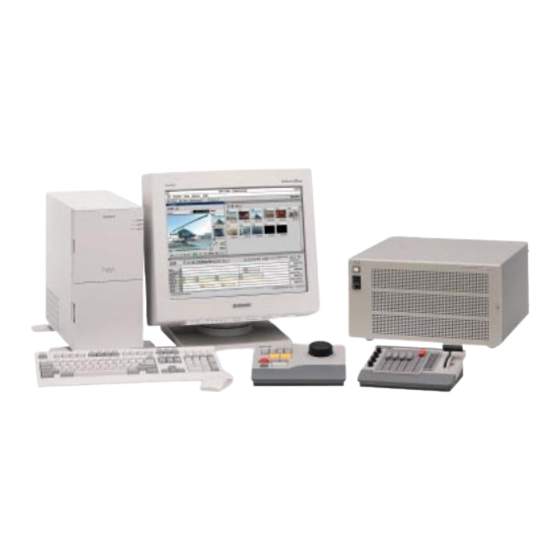
- Page 1 DIGITAL NEWS EDITING WORKSTATION DNE-1000 EDITING CONTROL PANEL BKNE-1010 EDITING FADER PANEL BKNE-1011 EXTENDED INPUT AND KEYER BOARD BKNE-1030 VIDEO EFFECTS BOARD BKNE-1040 3D/LIGHTING/TRAIL EFFECTS BOARD BKNE-1041 OPERATING PROGRAM BZNE-1010/1020 MAINTENANCE MANUAL Part 1 1st Edition...
- Page 2 When this product is installed in a rack, please make sure that the internal air ambient temperature of the rack is within the specified limit of this product. DNE-1000 Serial No. 10001 and Higher BKNE-1010 Serial No. 10001 and Higher 4.
-
Page 3: Table Of Contents
Installation of Optional Boards .......... 1-22 (E) 1-9. Switch Settings on Boards and LEDs Description ......1-24 (E) 1-9-1. DNE-1000 ................1-24 (E) 1-9-2. BKNE-1010 ................ 1-28 (E) 1-9-3. BKNE-1011 ................ 1-28 (E) 1-10. Hard Reset (DNE-1000) ..............1-28 (E) 1(E) DNE-1000... - Page 4 1-11. Confirmation and Adjustment of Secondary Power Supply Voltage ............1-29 (E) 1-11-1. DNE-1000 ................1-29 (E) 1-11-2. BKNE-1010 ................ 1-31 (E) 1-12. Initial Set-up of System ............... 1-31 (E) 2. Service Overview 2-1. DNE-1000 ..................... 2-1 (E) 2-1-1. Removal of Exterior Parts ............ 2-1 (E) 2-1-2.
- Page 5 5. Cleaning 5-1. Front Panel .................... 5-1 (E) 5-2. Fan ......................5-1 (E) 6. Overall Block Diagrams 6-1. DNE-1000 ....................6-2 6-2. BKNE-1010 ....................6-4 6-3. BKNE-1011 ....................6-6 3(E) DNE-1000...
-
Page 6: Manual Structure
Besides this Maintenance Manual Part 1, the following manuals are available for DNE-1000. • Operation Manual (Supplied with DNE-1000.) This manual explains the overview of DNE-1000 and optional boards, and the system configuration examples. Part number : 3-858-649-01 • Maintenance Manual Part 2 (Not supplied with DNE-1000.) -
Page 7: Installation
1-2-2. Power Cord Avoid placing or using this unit where it will be exposed to The power cord is not supplied with DNE-1000. Be sure to greasy fumes, steam, dampness and dust environments. use the power cord that is applicable to places in the world. -
Page 8: Connectors
PRIMARY INPUT BNC coaxial connector plug EDITOR Included with DNE-1000. DIGITAL OUTPUT EDITOR D-sub 9-pin, Male WORD SYNC OUTPUT Connector 9-pin, Male REF IN... -
Page 9: Input And Output Signals Of Connectors
The input and output signals of the connectors on the rear panel are specified in the following table. And refer to the following illustration for the pin positions of the connectors. 1-4-1. DNE-1000 PGM OUT MONITOR AUX INPUT WORD SYNC... - Page 10 Ground ETX_ Transmitted data (_) (*6) : When BKNE-1030 (IF-609 board) is attached to –– –– DNE-1000, it is possible to use the DEVICE ERX_ Received data (_) CONTROL from E to J. +12 V Power supply +12 V ––...
- Page 11 GPI R x GPI R xG x ; 1~4 (*9) : The selection operation of the GPI outputs (TTL) from T1 to T4 is simmetric with respect to it of the GPI outputs (RELAY) from T1 to T4. 1-5(E) DNE-1000...
-
Page 12: Bkne-1010
Knob data 4 from BKNE-1011 (_) VIDEO FADER (_) Data of Video fader from BKNE-1011 (_) AUDIO FADER-B Data of slide fader from BKNE-1011 AUDIO FADER-D Data of slide fader from BKNE-1011 FG E/N Data of connection evaluation for BKNE-1011 1-6(E) DNE-1000... - Page 13 –– –– –– Ground Ground SERIAL BUS LD (+) Received data from DNE-1000 to level meter (+) +12 V Power supply +12 V from DNE-1000 SERIAL BUS LD (_) Received data from DNE-1000 to level meter (_) +12 V Power supply +12 V from DNE-1000...
-
Page 14: Bkne-1011
Knob data 4 to BKNE-1010 (_) VIDEO FADER (_) Data of video fader to BKNE-1010 (_) AUDIO FADER-B Data of slide fader to BKNE-1010 AUDIO FADER-D Data of slide fader to BKNE-1010 FG E/N Data of connection evaluation for BKNE-1011 1-8(E) DNE-1000... -
Page 15: Example Of System Connection
1-5. Example of System Connection 1-5. Example of System Connection 1-5-1. Stand Alone System 1-9(E) DNE-1000... -
Page 16: Server System
1-5. Example of System Connection 1-5-2. Server System 1-10(E) DNE-1000... -
Page 17: Server System (Fast Transfer)
1-5. Example of System Connection 1-5-3. Server System (Fast Transfer) 1-11(E) DNE-1000... -
Page 18: Attachment Of Dne-1000
1-6. Attachment of DNE-1000 1-6. Attachment of DNE-1000 1-6-1. External Dimensions Mass : 27kg (with all optional boards in stalled) 25.2 475.2 (Top view) (*1) 4-M4 101.6 83.7 304.8 (Front view) (Right side view) Unit : mm (*1) : If using the packed screw of BVTT 4 x 8, this hole’s size is M4. -
Page 19: Space For Attachment
Board Front panel Unit : mm When DNE-1000 is mounted in a rack, the maximum traveling distance is showed as below. Maximum traveling distance 581 Distance to the center of the slide rail Height of the unit mounted in a rack... -
Page 20: Rack Mounting
1-6-3. Rack Mounting Procedures 1. Pull out the inner member while pressing the stopper DNE-1000 can be mounted in a 19-inch standard rack. Be of the rack mount rail RMM-30. sure to use an optional rack mount rail RMM-30. Outer member <Required parts>... - Page 21 1-6. Attachment of DNE-1000 3. Loosen the screws secured the rear bracket to the outer 5. Fully press the inner members to the outer members member. Adjust the positions of the front and rear while pressing the stoppers of the inner members and bracket.
-
Page 22: Attachment Of Control Panel (Bkne-1010/1011)
1-7. Attachment of Control Panel (BKNE-1010/1011) 1-7. Attachment of Control Panel (BKNE-1010/1011) 1-7-1. External Dimensions BKNE-1010 (Rear view) 48.3 18.3 (Top view) (Right side view) Unit : mm BKNE-1011 (Rear view) 48.3 18.3 (Top view) (Right side view) Unit :mm 1-16(E) DNE-1000... -
Page 23: Space For Attachment
1-7. Attachment of Control Panel (BKNE-1010/1011) 1-7-2. Space for Attachment When attaching BKNE-1010/1011 in the console, drill to the console as in the following dimensions. 10.5 16.5 (237) Unit : mm 1-17(E) DNE-1000... -
Page 24: Connection Of Control Panel
1-7. Attachment of Control Panel (BKNE-1010/1011) 1-7-3. Connection of Control Panel Use the two D-sub cables included with DNE-1000 and BKNE-1011, and connect the control panel (BKNE-1010/1011) to DNE-1000. (Figure for Connection) D-sub 15-pin cable (Included with DNE-1000) D-sub 25-pin cable (Included with BKNE-1011) -
Page 25: Replacement Of Key Tops
3 By turning the specified screw counterclockwise, the operation of the fader lever becomes fast. Cap pull tool (+) Driver Hook the tool here and pull out the key top. (Fig-1) (Fig-2) 3. Attach the new key top. BKNE-1011 screw (B3 x 14) 1-19(E) DNE-1000... -
Page 26: Installation Of Options
1-8. Installation of Options 1-8-1. Installation of Plug-in Boards Optional Equipments for DNE-1000 DNE-1000 can be used for various systems, and its functions can be extended by selecting the optional boards. Each plug-in board must be installed in the corresponding... - Page 27 IO-122 APR-14 Audio process board BKNE-1040 VSE-22 Special effect control board BKNE-1041 Video special effect board SEC-39 BKNE-1040 VSW-45 Video switcher board Video interface board VIF-12 (Not used) (Not used) IF-609 BKNE-1030 CPU-211 Interface board System control board 1-21(E) DNE-1000...
-
Page 28: Installation Of Optional Boards
2. 7. Install the board retainer in the reverse order of the steps 1 through 2. When installing the board retainer, secure them with the screws (B 3x6) that are packed with DNE-1000. Eject levers Board retainer Board... - Page 29 When installing the optional board, make sure that the connectors are connected tightly. If the connectors cannot be connected completely, the optional board may be placed in the other way. Slot 4 VSE-22 board SEC-39 board Slot 9 IF-609 board CPU-211 board 1-23(E) DNE-1000...
-
Page 30: Switch Settings On Boards And Leds Description
Do not use. CN8 (A13) : E-CPU test The addresses on the boards are shown by ( ) marks. This connector is used for the factory-shipped adjust- 1-9-1. DNE-1000 ment. Do not use. APR-14 board CN11 (B12) : C-CPU test... - Page 31 This LED is indicated the operation status of P-CPU. Light ; The P-CPU starts up and the processing is D410 “PA2” (Green) (A5) : completed. When the RS-232C TX signal (Transmitting data) is Lights off ; The P-CPU does not start up. transmitted, this LED lights. 1-25(E) DNE-1000...
- Page 32 FF ; Not used. accessed from the C-CPU when resetting. (Some CPUs that do not run exist.) F1 ; External interrupt The interrupt (INT3) that may not occur occurs at the C-CPU. F2 ; Not used. F3 ; Not used. 1-26(E) DNE-1000...
- Page 33 When receiving the reference signal, this LED lights. D104 (Yellow) (A6) : 525/625 system mode When selecting to the 625 system, this LED lights. D105 (Red) (A6) : Ref. err When the receiving reference signal is abnormal, this LED lights. 1-27(E) DNE-1000...
-
Page 34: Bkne-1010
1-9. Switch Settings on Boards and LEDs Description 1-10. Hard Reset (DNE-1000) 1-10. Hard Reset (DNE-1000) 1-9-2. BKNE-1010 1. CPU-206 Board Open the front panel and push the system reset switch S100 (A6) on the CPU-211 board, or turn OFF/ON the power switch. -
Page 35: Confirmation And Adjustment Of
1-11. Confirmation and Adjustment of Secondary Power Supply Voltage 1-11-1. DNE-1000 DNE-1000 has the power supply of +5 V(A), +5 V(B), CPU-211 board _5 V, and +12 V. The power indicator is used the +5 V(A) and the fan is... - Page 36 Rear panel 3. After the adjustment, detach the probes of the digital voltmeter, attach the blind plate and close the front panel. +12V 1-pin 3-pin +12V 1-pin 3-pin Adjustment driver Blind plate BVTT 3 1-30(E) DNE-1000...
-
Page 37: Bkne-1010
2 Vol. 1. 5. After the confirmation, detach the two probes of the digital voltmeter and attach the upper panel assembly. Upper panel assembly BVWH 3x8 (GIZA TITE) TPE3 (GND) CPU-206 board (+5 V) BVWH 3x8 (GIZA TITE) 1-31(E) DNE-1000... -
Page 39: Service Overview
To avoid shock hazards and/or damage to the mounted circuit boards, be sure to turn off the power switch, and then turn off the breaker at the outside of DNE-1000 or unplug the power cord before inserting or pulling out the exterior parts. -
Page 40: Location Of Main Parts
To charge the large storage capacitor sufficiently, turn on and descriptions that are listed in this section. the power of DNE-1000 for more than about thirty minutes. Spare Parts The sufficiently charged large storage capacitor enables... -
Page 41: Bkne-1010
BVWH 3x8 (GIZA TITE) . To avoid shock hazards and/or damage to the mounted circuit boards, be sure to turn off the power switch of DNE-1000 before inserting or pulling out the exterior BVWH 3x8 parts. KY-343 board (GIZA TITE) . -
Page 42: Location Of Main Parts
To avoid shock hazards and/or damage to the mounted PWH 3x6 circuit boards, be sure to turn off the power switch of DNE-1000 before installing and/or removing the mounted circuit board. 1. CPU-206 Board (1) Remove the upper panel assembly. -
Page 43: Spare Parts
Spare Parts Hexagon screws CN bracket Description Part No. (5) Install the CPU-206 board in the reverse order of the Mounted Circuit Board, CPU-206 A-8312-201-A steps (1) through (4). Mounted Circuit Board, KY-343 A-8312-203-A Search Dial Block Assembly A-6734-253-B 2-5(E) DNE-1000... -
Page 44: Bkne-1011
. To avoid shock hazards and/or damage to the mounted Slide knobs circuit boards, be sure to turn off the power switch of DNE-1000 before inserting or pulling out the exterior parts. . To avoid shock hazards and/or fire by a short circuit, be sure to set the removed exterior parts on the places that will not be established a short circuit. -
Page 45: Location Of Main Parts
Upper panel assembly Heat sink 8. Remove the three screws, and the pad and the upper panel. Upper panel PWH 3x6 9. Install the pad and the upper panel in the reverse order of the steps 1 through 8. 2-7(E) DNE-1000... -
Page 46: Installation And Removal Of Boards
PTTWH 3x6 (S TIGHT) circuit boards, be sure to turn off the power switch of CPU-207 board DNE-1000 before installing and/or removing the mounted circuit board. 1. CPU-207 Board (1) Remove the fader grip, the four knobs and the five slide knobs. - Page 47 (6) Remove the three screws and the LD-77 board. (6) Install the SW-871 board in the reverse order of the steps (1) through (5). B 2.6x4 LD-77 board VR fitting bracket (7) Install the LD-77 board in the reverse order of the steps (1) through (6). 2-9(E) DNE-1000...
-
Page 48: Spare Parts
Spare Parts Description Part No. Mounted Circuit Board, CPU-207 A-8312-208-A Mounted Circuit Board, LD-77 A-8312-211-A Mounted Circuit Board, SW-871 A-8312-210-A Fader Assembly (lever) A-8262-836-A Fader (slide) 1-241-009-12 Rotary Encoder (knob) 1-466-955-11 Rotary Encoder (lever) 1-467-705-11 2-10(E) DNE-1000... -
Page 49: Replacement Of Main Parts
DNE-1000 or And if the fan is used over a prolonged period, the rotation unplug the power cord before replacing the main parts. -
Page 50: Bkne-1010
After installing the fan, insert the harness between the DNE-1000 before replacing the main parts. upper fan and the lower fan. Pull the harness toward 3-2-1. Replacement of Search Dial the arrow A, then hold it with the ferrite bead. -
Page 51: Bkne-1011
(2) Remove the upper panel assembly. DNE-1000 before replacing the main parts. (Refer to the step 3 of the section 2-3-1.) (3) Disconnect the two connectors (CN7 and CN8) on the 3-3-1. -
Page 52: Replacement Of Fader
Heat-shrinkable tube Fader VR fitting bracket B 3x4 (7) Install a new fader in the reverse order of the steps (1) through (6). When soldering the harness to the fader, put the heat- shrinkable tube (ø3) through the harness. 3-4(E) DNE-1000... -
Page 53: Trouble Shooting (Bkne-1010/1011)
This test is confirmed to operate the video fader of BKNE- 1011. 8. Test of Audio Faders (BKNE-1011) This test is confirmed to operate the audio fader of BKNE- 1011. 9. Test of Knobs (BKNE-1011) This test is confirmed to operate the knob of BKNE-1011. 4-1 (E) DNE-1000... -
Page 54: Required Tools
2. Connector Tool for RS-232C Loop Back Test This connector is connected between 2-pin and 3-pin of the D-sub 9-pin female connector. (Other pins are opened.) Pin No. Signal name [D-sub 9-pin . Male] RXIN — EXT VIEW — 4-2 (E) DNE-1000... -
Page 55: Positions Of Knobs And Buttons On The Panel
“INPUT” LED KNOB LEVER INPUT “MIX” LED OVER “1/2” LED “KNOB 1 to 4” “3/4” LED “L/R” LED -∞ “VIDEO FADER LEVER” “AUDIO LEVEL METER R” LED “AUDIO FADER KNOB” “AUDIO LEVEL METER L” LED (Top view) 4-3 (E) DNE-1000... -
Page 56: Starting Of Self Diagnostics Mode
4-1-3. Starting of Self Diagnostics Mode 4-1-4. Procedures for Tests 1. Test of RAM (BKNE-1010) 1. Turn OFF the power switch of DNE-1000. 2. Attach BKNE-1011 to BKNE-1010. 3. Move down the video fader lever and five audio fader (1) Confirmation of Internal RAM knobs. - Page 57 RS-232C of the “EDITOR” connectors and is con- firmed the communication operation for them. The communication operation of the RS-422A and RS- 232C is separately tested. The confirmation of the operation is used the “AUDIO LEVEL METERs L and R”, “3/4” LEDs. 4-5 (E) DNE-1000...
- Page 58 [GO|TO|OUT] If the test conclusion is OK (When turning the search –N –1 dial clockwise and counterclockwise, all of the twenty- five LEDs light.), the “MIX” LED lights. [STILL] [PLAY] [MARK|IN] [MARK|OUT] [REC] [PVW] [ADD] [ALL|STOP] 4-6 (E) DNE-1000...
-
Page 59: Ending The Self Diagnostics Mode
This test is confirmed the transition operation of the audio fader on BKNE-1011. The “1”, 2", “3”, “4”, “M” and “AUDIO LEVEL METER After turning OFF the power switch of DNE-1000, turn R” LEDs are used to confirm the operation. ON the power switch of DNE-1000. -
Page 60: Trouble Shooting
. The CN4 on the CPU-206 board is a cold joint. . The harness (KEY1) between CN4 on the CPU-206 board and CN2 on the KY-343 board is not connected or is a poor connection. 4-8 (E) DNE-1000... - Page 61 . The IC2 on the CPU-207 board is at fault or is a cold joint. . The connection between CN7 on the CPU-207 board and video fader is not connected or is a poor contact. . The video fader is at fault. 4-9 (E) DNE-1000...
- Page 62 . Any of the CN1 through CN5 on the SW-871 board are cold joints. . The connection between one of the CN2 through CN5 on the SW-871 board and each rotary encoder is not connected or is a poor connection. . The rotary encoder is at fault. 4-10 (E) DNE-1000...
-
Page 63: Cleaning
When washing the filter, be sure to dry it well. vacuum cleaner. 4. Adhere the filter to the adhesive tapes. Front panel Adhesive tape Filter Adhesive tape 2. Fan of Rear side (1) Remove dust on the fan and the fan cover using a vacuum cleaner. Fans 5-1(E) DNE-1000... -
Page 65: Overall Block Diagrams
Section 6 Overall Block Diagrams DNE-1000... -
Page 66: Dne-1000
DNE-1000 OVERALL Block Diagram 6-1. DNE-1000 EFFECT CPU CONTROL BUS XPT-9 VIF-12 Control Control Output Audio Frame Proc. Combine Delay Output Frame Proc. Delay KEYER DSKS DSKF EXTK FRGD Video FRGDCC Adjust BKGD Video BKGDCC Adjust FM1I FM2I VITC VIRTUAL KEY... - Page 67 DNE-1000 OVERALL Block Diagram DEVICE CONTROL (RS-422A) PANEL IF-609 D CPU 4 D CPU 3 D CPU 2 D CPU 1 D CPU 0 P CPU ADRS DATA PGM Out(D) CONTROL C CPU BUS ADD. GUI (10BASE-5) 80 x 60...
-
Page 68: Bkne-1010
BKNE-1010 OVERALL Block Diagram 6-2. BKNE-1010 DC-DC 12.288MHZ 6-12V AC ADAPTOR Q1 ,2 ,3 RS-422A TO DNE-1000 DRIVER/ HD647180 (D-SUB 15-PIN MALE) RECEIVER IC27 ADDRESS BUS DATA BUS CONTROL RS-232C (*1) DRIVER/ RECEIVER IC18 SERIAL CONVERTER IC29 RS-422A SELECTER DRIVER/... - Page 69 BKNE-1010 OVERALL Block Diagram EP-ROM STATIC RAM ADDRESS (PROGRAM) (DATA) DECODER IC26 IC28 IC16 ,25 DIAL ASSY A/D CONVERTER COUNTER DIAL COUNTER REF. IC10 ,12 ,23 IC24 IC15 VOLTAGE SELECTER IC14 Q6 ,7 KEY SW KY-343 CPU-206 OVERALL Block Diagram DNE-1000...
-
Page 70: Bkne-1011
BUFFER SW-871 IC2,7 STATUS LED VIDEO FADER ASSY FROM BKNE-1010 BAR LED (D-SUB 15-PIN FEMALE) BUFFER SHIFT REGISTER BAR LED RS-422A RECEIVER CONTROL IC1,2,3, IC11,14,15,17, 18,19,22,23 LD-77 IC10 AUDIO FADER BUFFER FADER VR 10K/B IC3,4 CPU-207 OVERALL Block Diagram DNE-1000... - Page 71 The material contained in this manual consists of screws, and all other exposed metal parts for AC information that is the property of Sony Corporation and leakage. Check leakage as described below. is intended solely for use by the purchasers of the equipment described in this manual.
- Page 72 BKNE-1010 (SY) BKNE-1011 (SY) Printed in Japan Sony Corporation DNE-1000 (SY) J, E 1997. 3 16 Image & Sound Communication Company 3-191-761-01 (1) ©1997 Published by Engineering Services Dept.