Table of Contents
Advertisement
Quick Links
Advertisement
Table of Contents

Related Manuals for Bosch AUTODOME inteox 7000i 2MP


Summary of Contents for Bosch AUTODOME inteox 7000i 2MP
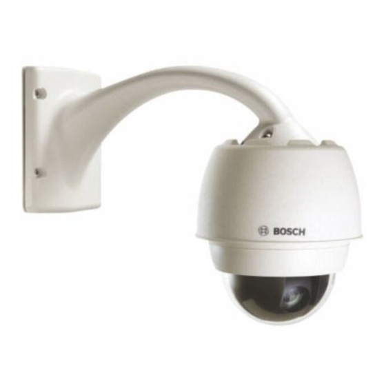
- Page 1 AUTODOME inteox 7000i ‑ 2MP (pendant) Installation Manual (pendant)
-
Page 3: Table Of Contents
Ethernet Connections 13.4 Fiber Optic Ethernet Media Converter (Optional) 13.5 Alarms and Relay Connections 13.6 Audio Connections (Optional) Troubleshooting 14.1 Rebooting the unit 14.2 Customer Service and Support Maintenance Support Bosch Security Systems Installation Manual (pendant) 2020-07 | 1.0 |... -
Page 4: Safety En
Legal Information Copyright This manual is the intellectual property of Bosch Security Systems, and is protected by copyright. All rights reserved. Trademarks All hardware and software product names used in this document are likely to be registered trademarks and must be treated accordingly. -
Page 5: Important Safety Instructions
For 24 VAC units, voltage applied to the unit's power input should not exceed ±10%, or 28 VAC. User-supplied wiring must comply with local electrical codes (Class 2 power levels). Do not ground the supply at the terminals or at the unit's power supply terminals. Bosch Security Systems Installation Manual (pendant) 2020-07 | 1.0 |... - Page 6 16. Attachments, changes or modifications - Only use attachments/accessories specified by the manufacturer. Any change or modification of the equipment, not expressly approved by Bosch, could void the warranty or, in the case of an authorization agreement, authority to operate the equipment.
- Page 7 ® Electrical Code (NEC)), Canadian Electrical Code, Part I (also called CE Code or CSA C22.1), and all applicable local codes. Bosch Security Systems accepts no liability for any damages or losses caused by incorrect or improper installation. Warning! INSTALL EXTERNAL INTERCONNECTING CABLES IN ACCORDANCE TO NEC, ANSI/NFPA70 (FOR US APPLICATION) AND CANADIAN ELECTRICAL CODE, PART I, CSA C22.1 (FOR CAN...
-
Page 8: Important Notices
Camera signal - Protect the cable with a primary protector if the camera signal is beyond 140 feet, in accordance with NEC800 (CEC Section 60). Environmental statement - Bosch has a strong commitment towards the environment. This device has been designed to respect the environment as much as possible. - Page 9 Ce produit est un appareil de Classe A. Son utilisation dans une zone résidentielle risque de provoquer des interférences. Le cas échéant, l’utilisateur devra prendre les mesures nécessaires pour y remédier. Bosch Security Systems Installation Manual (pendant) 2020-07 | 1.0 |...
- Page 10 Any such modifications could void the user's authority to operate the equipment. If necessary, the user should consult the dealer or an experienced radio/television technician for corrective action. 2020-07 | 1.0 | Installation Manual (pendant) Bosch Security Systems...
-
Page 11: Customer Support And Service
AUTODOME inteox 7000i - 2MP (pendant) Safety EN | en Customer Support and Service If this unit needs service, contact the nearest Bosch Security Systems Service Center for authorization to return and shipping instructions. USA and Canada Telephone: 800-289-0096, option 5 Fax: 800-366-1329 Email: repair@us.bosch.com... -
Page 12: Unpacking
Sales or Customer Service Representative from Bosch Security Systems. – Do not use this product if any component appears to be damaged. Please contact Bosch Security Systems in the event of damaged goods. – The original packing carton (if undamaged) is the safest container in which to transport the unit and must be used if returning the unit for service. -
Page 13: Product Description
The camera has been designed for quick and easy installation, a key feature from Bosch IP video security products. All housings feature recessed screws and latches for increased tamper resistance. - Page 14 The following table lists the optional parts, sold separately, that you may need for attaching a Pendant to the Roof Parapet and Pipe mount packages: Mounting Options Part Numbers Optional Flat Roof Mount Adapter for VGA-ROOF-MOUNT LTC 9230/01 2020-07 | 1.0 | Installation Manual (pendant) Bosch Security Systems...
-
Page 15: Pre-Installation Checklist
(not supplied). Warning! To minimize the potential for corrosion on the housing, use only Bosch hardware and mounts. See number 5 (Installation in a corrosive environment) in the section Recommended Use of Your Camera for more information. -
Page 16: Stabilization
Cameras attached to a pole, roof, or to a bridge are especially vulnerable. Bosch offers the following recommendations to stabilize an AUTODOME camera and to decrease the affects of vibration on transmitted images, privacy masks, and Intelligent Tracking. - Page 17 Avoid neon lights, flashing lights, night time lights, and reflected light (from a window or mirror, for example). The flickering of these lights can affect the Intelligent Tracking operation. – Avoid motion from moving leaves/branches that present a persistent fixed motion. Bosch Security Systems Installation Manual (pendant) 2020-07 | 1.0 |...
-
Page 18: Preparing The Bubble
Notice! To avoid excessive moisture saturation inside the housing, limit the amount of time that the bubble is disconnected from the housing. Bosch recommends that the bubble be removed from the housing for no more than five (5) minutes. Remove the bubble from a pendant housing Using both hands, apply a firm counterclockwise (looking up at the dome) rotational force on the pendant bubble assembly to set the bubble latch. -
Page 19: Optional) Installing An Sd Card
Follow the steps in one of these sections (depending on the type of camera mount): Replace the bubble in an in-ceiling housing or Replace the bubble in a pendant housing. Bosch Security Systems Installation Manual (pendant) 2020-07 | 1.0 |... -
Page 20: Replacing The Trim Ring And Bubble
Replace the bubble in a pendant housing Insert the bubble and trim ring assembly into the pendant housing. Rotate the assembly clockwise until it locks. The latch mechanism makes a click when it locks. 2020-07 | 1.0 | Installation Manual (pendant) Bosch Security Systems... -
Page 21: Mount Power Supply Box (Wall, Mast (Pole), And Corner Mounts)
100-380 mm (4-15 in.). You must use a banding tool (sold separately) for a mast or pole installation. Follow the instructions provided with the banding tool to securely mount the Mast Plate to the pole. Contact your Bosch Sales Representative to order Banding Tool P/N TC9311PM3T. - Page 22 Warning! For units intended to be installed outdoors: All wiring (power and I/O cabling) connecting to the unit must be routed separately inside different permanently earthed metal conduits (not supplied). 2020-07 | 1.0 | Installation Manual (pendant) Bosch Security Systems...
-
Page 23: Installing The Pendant Arm Wall, Corner, And Mast (Pole) Mounts
To connect alarm inputs and outputs, attach the supplied 6-pin Alarms In and the 4-pin Alarms Out connector plugs with flying lead wires to the appropriate incoming alarm wires. Alarm Out 4 is a relay. Bosch Security Systems Installation Manual (pendant) 2020-07 | 1.0 |... - Page 24 If you are connecting supervised alarms and relays, attach the supplied 7-pin Relay Connector to the appropriate incoming wires. Refer to Make Connections in the Power Supply Box, page 31 for additional information. 2020-07 | 1.0 | Installation Manual (pendant) Bosch Security Systems...
- Page 25 Series cameras: If you are mounting an AUTODOME 7000 Series camera to an ARM mount that was wired for an earlier model of Bosch AUTODOME, you must either re-wire cable 8 to be audio input and output, or disconnected it from the power supply.
- Page 26 Warning! For units intended to be installed outdoors: All wiring (power and I/O cabling) connecting to the unit must be routed separately inside different permanently earthed metal conduits (not supplied). 2020-07 | 1.0 | Installation Manual (pendant) Bosch Security Systems...
-
Page 27: Route Power Through Intermediate Power Supply Box
6 5 4 3 2 1 Figure 9.3: VG4-PSU1/VG4-PSU2 120/230 VAC Power In Transformer Ground Wire In/Out Conduit (1/2 in. [15 mm] NPS Fitting P101 Connector 24 VAC Power Out to VG4-PA0 P107 Connector Bosch Security Systems Installation Manual (pendant) 2020-07 | 1.0 |... - Page 28 Connect the third wire to pin 3 (Earth Ground) connector. Refer to connector P107 in the table above and to the image below for an illustration of these connections: Figure 9.5: Outgoing 24 VAC power supply 2020-07 | 1.0 | Installation Manual (pendant) Bosch Security Systems...
- Page 29 Ground Wire P101 Connector Control Data and Video In/Out Wires (analog models only) 9. Follow the instructions in Attach Pendant Arm to Power Supply Box, page 30 to continue the installation. Bosch Security Systems Installation Manual (pendant) 2020-07 | 1.0 |...
-
Page 30: Attach Pendant Arm To Power Supply Box
Serious injury or death can occur if the hinge pins of the Pendant Arm are not fully engaged (locked) to the Power Supply Box. Exercise caution before releasing the Pendant Arm. 2020-07 | 1.0 | Installation Manual (pendant) Bosch Security Systems... -
Page 31: Make Connections In The Power Supply Box
After all wiring is complete, close the cover door and tighten the two (2) captive screws on the cover door to 10-12 N-m (90-105 in.-lbs) to ensure the Power Supply Box is watertight. Bosch Security Systems Installation Manual (pendant) 2020-07 | 1.0 |... -
Page 32: Installing The Vga-Pend-Wplate
Follow the instructions provided with the banding tool to securely mount the Mast Plate to the pole. Contact your Bosch Sales Representative to order Banding Tool P/N TC9311PM3T. - Page 33 Route and Connect Wires to a Power Supply Box The illustration below depicts the power and control cables connected to the Pendant Arm: Figure 9.10: Pendant Arm Cables Cable Cable Grounding Strap (black) UTP Video/Ethernet (blue) Bosch Security Systems Installation Manual (pendant) 2020-07 | 1.0 |...
- Page 34 Wire input conduit holes Connect the incoming 24 VAC power wires to the 5-pin, 24 VAC Power In mating connector (supplied with the Mounting Plate kit) for the camera and for the Heater. 2020-07 | 1.0 | Installation Manual (pendant) Bosch Security Systems...
-
Page 35: Attach Pendant To Arm And Tighten
Tilt the bottom of the dome toward the pendant arm base and place the mounting hook, located on top of the dome housing, over the recessed hinge pin of the arm. Bosch Security Systems Installation Manual (pendant) 2020-07 | 1.0 |... - Page 36 10-12 N-m (90-105 in.-lbs). Caution! You must tighten the two mounting screws to a minimum torque of 10-12 N-m (90‑105 in.-lbs) to ensure a proper seal between the arm and the housing. 2020-07 | 1.0 | Installation Manual (pendant) Bosch Security Systems...
-
Page 37: Installing The Roof Parapet And Pipe Mounts
The VGA-ROOF-MOUNT is a stationary mount intended for rooftop parapet vertical walls. It is made of light weight aluminum with a corrosion-resistant finish and is used for all Bosch AUTODOME cameras up to a rated load of 29 kg (64 lb). This mount can be fitted to the inside or outside of parapet walls and can swivel for ease of positioning and for servicing the camera. - Page 38 Refer to the Connection, page 52 chapter for wire specifications and distances. Route the high voltage 115/230 VAC lines through the earth-grounded conduit fitting on the left side of the box. 2020-07 | 1.0 | Installation Manual (pendant) Bosch Security Systems...
- Page 39 Route the control wires from the Power Supply to the Pipe Interface Board. Then attach the supplied six (6) pin control data connector to the wires in the Power Supply Box. Refer to Wire the Pipe Interface Board, page 44 . Bosch Security Systems Installation Manual (pendant) 2020-07 | 1.0 |...
- Page 40 24V NC P106 GND TXD RXD C+ C- Figure 10.2: Fiber Optic Ethernet Module installed 1 RJ45 Ethernet socket 2 Port for SFP module (sold separately) 3 Fiber Optic cable (user-supplied) 2020-07 | 1.0 | Installation Manual (pendant) Bosch Security Systems...
- Page 41 T 2.0 A T 3.15 A The following table lists the Power Supply Box connectors: Connector Pin 1 Pin 2 Pin 3 Pin 4 Pin 5 Pin 6 Ground Grounding Screw Bosch Security Systems Installation Manual (pendant) 2020-07 | 1.0 |...
-
Page 42: Attach Cover Door To Power Supply Box
When the hinges are aligned, release the top hinge pin to engage its mating hinge on the power box. Then release the bottom hinge pin from the Hinge Pin Stop to complete attaching the Cover Door to the Power Supply Box. 2020-07 | 1.0 | Installation Manual (pendant) Bosch Security Systems... -
Page 43: Installing The Vg4-A-9543 Pipe Mount
Route the power, video, control, and alarm wires through the Top-Mounting Flange and down the pipe. Wrap at least five layers of Teflon tape around the threads. Bosch Security Systems Installation Manual (pendant) 2020-07 | 1.0 |... -
Page 44: Wire The Pipe Interface Board
This section provides instructions for connecting wires and cables to the Pipe Interface Board, as illustrated below. Refer to the Connection, page 52 chapter for cable and wiring recommendations and specifications. AGND OUT 3 OUT 2 OUT 1 Figure 10.6: Pipe Interface Board Connections 2020-07 | 1.0 | Installation Manual (pendant) Bosch Security Systems... - Page 45 Alarms In (EOLR P104 Ground Supervised, 1-2) 26-16 Alarm 2 Alarm 1 Earth Ground Relay Output P104 Normally Closed 26-16 Common Normally Open Dome Power P101 Dome 24 VAC 18-14 Earth Ground Bosch Security Systems Installation Manual (pendant) 2020-07 | 1.0 |...
- Page 46 BROWN P102 ORANGE GREEN WHITE BROWN ORANGE P103 GREEN YELLOW BLUE P104 Figure 10.7: Alarm and relay connectors 4-pin Alarm 6-pin Alarm In 7-pin Relay Connector (P104) Connector (P102) Connector (P103) 2020-07 | 1.0 | Installation Manual (pendant) Bosch Security Systems...
- Page 47 Be careful not to strip the threads when tightening the Pipe Interface Board retaining screws. Figure 10.8: Pipe Interface Board to Dome Cap Assembly Interface Board Retaining Screws (3) Pendant Mounting Screws (2) Bosch Security Systems Installation Manual (pendant) 2020-07 | 1.0 |...
-
Page 48: Attach Pendant To Pipe And Tighten
Hold the housing firmly in position and alternately tighten the two (2) 5-mm Allen head mounting screws from above to a torque value of 10-12 N-m (90-105 in.-lbs). 2020-07 | 1.0 | Installation Manual (pendant) Bosch Security Systems... -
Page 49: Make Connections In The Power Supply Box
Connect the 24 VAC to Dome plug, installed previously, to its mating connector P107 on the right side of the box. Connect the 115/230 VAC, 3-pin Power-in plug, installed previously, to its mating connector P101 on the left side of the box. Bosch Security Systems Installation Manual (pendant) 2020-07 | 1.0 |... -
Page 50: Finalizing Installation
AUTODOME inteox 7000i - 2MP (pendant) Finalizing installation Remove the plastic on the bubble After you complete all other installation steps, remove the plastic material that is protection for the bubble. 2020-07 | 1.0 | Installation Manual (pendant) Bosch Security Systems... -
Page 51: Replacing A Pendant Bubble
8. Clean the bubble according to the instructions in the section “Maintenance.” 9. Insert the replacement bubble and trim ring assembly into the pendant housing, and rotate it clockwise until it locks. The latch mechanism makes a click when locks. Bosch Security Systems Installation Manual (pendant) 2020-07 | 1.0 |... -
Page 52: Connection
IP Connection Network Switch Computer Notice! You can also use the Bosch Video Client software application to configure the network settings for an AUTODOME 7000 Series camera. Go to www.boschsecurity.com to download the Configuration Manager software and Operating Manual. 13.2... -
Page 53: Ethernet Connections
IP network using the built-in Web server. In addition, power can be supplied over the Ethernet cable using the Bosch High PoE 60W midspan (sold separately). Power can also be supplied over the Ethernet cable to in-ceiling models and indoor/outdoor pendant models used in indoor applications (where the heater is not powered) using PoE+ PSEs (midspan switches) compliant with the IEEE 802.3at, class 4 standard. -
Page 54: Fiber Optic Ethernet Media Converter (Optional)
100 m (328 ft) Bandwidth 10 Base-T/100 Base-TX High PoE (required for pendants in outdoor applications that use Use the Bosch High PoE 60W midspan heaters) (sold separately). PoE+ (only for indoor models or indoor applications for pendant model IEEE 802.3at, class 4 standard... -
Page 55: Alarms And Relay Connections
Ground (Pin 7) From Configuration, select Interfaces > Alarm Inputs, select the number of the Alarm input and finally, select N.O. See the table below for contact and condition details. Bosch Security Systems Installation Manual (pendant) 2020-07 | 1.0 |... - Page 56 Configuring a Normally Open Non-supervised Alarm Connect the alarm to the appropriate input (3 through 7) and ground at the camera. Figure 13.4: N.O. - Normally Open Non-supervised Connections Dry Contact Dome Connector 2020-07 | 1.0 | Installation Manual (pendant) Bosch Security Systems...
- Page 57 5 and 32 V to complete the circuit, with a maximum voltage rating of 32 VDC @ 150 ma. Connect the appropriate stripped wire to the open connector (1, 2, or 3) of the transistor. Connect the appropriate stripped wire to the ground (GND) connector. Bosch Security Systems Installation Manual (pendant) 2020-07 | 1.0 |...
-
Page 58: Audio Connections (Optional)
Remove the 100 Ohm termination resistor from the C+ to C- terminals. Connect the audio line level source to the Audio_In+ (C+) input terminal. Connect the audio signal ground to the Audio_In- (C-) input terminal. 2020-07 | 1.0 | Installation Manual (pendant) Bosch Security Systems... - Page 59 Audio_Out– (TXD) Signal Ground Notice! Separate the audio cables from the AC power lines to avoid noise. To configure audio on the camera, refer to Basic Mode: Audio or Audio. Bosch Security Systems Installation Manual (pendant) 2020-07 | 1.0 |...
-
Page 60: Troubleshooting
If you cannot control the unit after the firmware upgrade, then cycle the power to the unit. If a power reset does not solve the problem, or if Configuration or video management software identifies the unit as “Videojet Generic,” then contact your Bosch Service Center for an RMA for the unit. -
Page 61: Customer Service And Support
AUTODOME inteox 7000i - 2MP (pendant) Troubleshooting | en 14.2 Customer Service and Support If this unit needs service, contact the nearest Bosch Security Systems Service Center for authorization to return and shipping instructions. Telephone: 800-366-2283 Fax: 800-366-1329 Email: cctv.repair@us.bosch.com... -
Page 62: Maintenance
Dry the bubble thoroughly with a dry nonabrasive cloth to prevent water spots. Never scrub the bubble with any abrasive material or cleaners. Bosch recommends cleaning the exterior of the bubble with NOVUS “No. 1” Plastic Clean & Shine (or equivalent), according to manufacturer’s instructions. Refer to www.novuspolish.com... -
Page 63: Support
Troubleshooting – Repair & Exchange – Product Security Bosch Building Technologies Academy Visit the Bosch Building Technologies Academy website and have access to training courses, video tutorials and documents: https://www.boschsecurity.com/xc/en/support/training/ Bosch Security Systems Installation Manual (pendant) 2020-07 | 1.0 |... - Page 64 | Support AUTODOME inteox 7000i - 2MP (pendant) 2020-07 | 1.0 | Installation Manual (pendant) Bosch Security Systems...
- Page 66 Bosch Sicherheitssysteme GmbH Bosch Security Systems, LLC Robert-Bosch-Ring 5 1706 Hempstead Road 85630 Grasbrunn Lancaster, PA, 17601 Germany www.boschsecurity.com © Bosch Sicherheitssysteme GmbH, 2020...