Samsung OfficeServ 7100 Technical Manual
Hide thumbs
Also See for OfficeServ 7100:
- Technical manual (709 pages) ,
- Service manual (291 pages) ,
- Installation manual (103 pages)
Table of Contents
Advertisement
Quick Links
OfficeServ 7100
TECHNICAL MANUAL
T A B L E
I N S TA L L AT I O N S E C T I O N
PART
DESCRIPTION
1
1.1
1.2
1.3
1.4
2
2.1
2.2
2.3
2.4
2.5
3
INSTALLING AND REPLACING BOARDS
3.1
3.2
3.3
3.4
3.5
3.6
4
4.1
5
5.1
5.2
O F
SITE REQUIREMENTS ............................................................... 1.1
GROUNDING CONDITIONS ....................................................... 1.2
POWER CONDITIONS ................................................................ 1.4
UNPACKING AND INSPECTION ................................................ 1.4
SYSTEM INSTALLATION PROCEDURE ..................................... 2.1
SELECTING INSTALLATION METHOD ...................................... 2.1
INSTALLING IN A RACK ............................................................. 2.1
INSTALLING ON A WALL ........................................................... 2.4
CONNECTING GROUND WIRES ............................................... 2.8
CABINET CONFIGURATION....................................................... 3.1
MP10 PROCESSOR CARD ......................................................... 3.2
INTERFACE CARDS ................................................................... 3.8
CONNECTING DAUGHTER CARD MODULES......................... 3.12
OTHER INTERFACE CARDS .................................................... 3.17
CONNECTING POWER FAIL TRANSFER................................. 3.29
CONNECTING EXTERNAL BATTERIES ..................................... 4.1
BEFORE CONNECTING POWER ............................................... 5.1
PROCEDURE FOR CONNECTING POWER ............................... 5.1
Home Page
TABLE OF CONTENTS APRIL 2007
C O N T E N T S
Table of Contents
INSTALLATION
PAGE
Advertisement
Chapters
Table of Contents

Related Manuals for Samsung OfficeServ 7100


Summary of Contents for Samsung OfficeServ 7100
-
Page 1: Table Of Contents
Table of Contents Home Page OfficeServ 7100 INSTALLATION TECHNICAL MANUAL TABLE OF CONTENTS APRIL 2007 T A B L E C O N T E N T S I N S TA L L AT I O N S E C T I O N... - Page 2 Table of Contents Home Page OfficeServ 7100 INSTALLATION TECHNICAL MANUAL TABLE OF CONTENTS APRIL 2007 CONNECTING C.O. LINES SAFETY PRECAUTIONS ............. 6.1 CONNECTING C.O. LINES ............6.1 CONNECTING STATIONS AND ADDITIONAL EQUIPMENT CONNECTING STATIONS ............7.1 CONNECTING ADDITIONAL EQUIPMENT ......7.13 POWER UP PROCEDURES PRE-CHECK ................
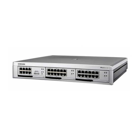
- Page 3 TECHNICAL MANUAL TABLE OF CONTENTS APRIL 2007 Figure 2.13 Grounding Figure 3.1 Front/Rear View of OfficeServ 7100 Cabinet Figure 3.2 Switch Setting Figure 3.3 Mounting a Modem Card on the MP10 Card Figure 3.4 Mounting a 4SWM or 4DLM on the MP10 Card Figure 3.5 Mounting the MP10 into Slot 0...
- Page 4 Table of Contents Home Page OfficeServ 7100 INSTALLATION TECHNICAL MANUAL TABLE OF CONTENTS APRIL 2007 Figure 4.1 Connecting an External Battery Figure 5.1 Connecting Power Figure 6.1 8TRK Card Ports (P1~P8) or 4TRM port (P1~P4) Figure 6.2 RJ-45 Port of TEPRI/TEPRIa Card Figure 7.1 RJ-45 Port of the 8SLI Card...
- Page 5 Table 3.8 Ports and LEDs of the 8DLI Card Table 3.9 16MWSLI Card Ports Table 3.10 Ports and LEDs of the 8SLI Card Table 3.11:MGI16 Front Panel Components Table 6.1 OfficeServ 7100 Line Conditions Table 7.1 Distance Between Stations and the System Table 7.2 Installation Tool Specification...
-
Page 6: Pre-Installation Information
• Do not install in close proximity to a fire sprinkler or other sources of water. • A dedicated commercial AC power outlet is required. Do not use extension cords. • Ensure that all wires and cables to and from the OfficeServ 7100 do not cross fluorescent lights or run in parallel with AC wires. -
Page 7: Grounding Conditions
The OfficeServ 7100 system requires that a supplementary earth ground be connected to the system. This is the preferred method of grounding the OfficeServ 7100. It should be noted that when the third wire ground becomes inferior it many prevent the digital data bus from canceling out noise. - Page 8 Obviously, it is important to have a good source of ground connected to the OfficeServ 7100 system to drain this energy off. Again, a good earth ground source is required by the OfficeServ 7100 system.
-
Page 9: Power Conditions
PART 1 APRIL 2007 1.3 POWER CONDITIONS The power supply card of the OfficeServ 7100 system receives AC input power or battery power, and supplies -48 V, -5 V, +5 V, +3.3 V, +12 V, and -54V (Battery Backup) to the system cabinet. -
Page 10: Installing Cabinets
2.1 SYSTEM INSTALLATION PROCEDURE The procedure of system installation is as follows. 1) Install the OfficeServ 7100 cabinet on a table, inside a data rack or on the wall depending on the installation environment. 2) Connect the ground to the ground lug located in the back of the cabinet. -
Page 11: Figure 2.1 Tools Required For Rack Installation
(The optional rack mount kit is required for this method. This kit is sold separately): 1) Attach the cabinet bracket to the bottom surface of the OfficeServ 7100 cabinet and fasten the bracket firmly with the two screws. Figure 2.2 Rack Installation (1) -
Page 12: Figure 2.3 Rack Installation
Table of Contents Home Page OfficeServ 7100 INSTALLATION TECHNICAL MANUAL PART 2 APRIL 2007 2) Slide the cabinet attaching the bracket in Step 1. Figure 2.3 Rack Installation (2) 3) Align the two holes of the cabinet bracket and the holes of the rack brackets, and fasten the cabinet to the rack with the two screws. -
Page 13: Installing On A Wall
TECHNICAL MANUAL PART 2 APRIL 2007 2.4 INSTALLING ON A WALL This section describes how to install the OfficeServ 7100 cabinet on a wall. The OfficeServ 7100 wall mount bracket is required (included with the cabinet). 2.4.1 Required Tools • Mid-sized Phillips screw driver •... -
Page 14: Figure 2.6 Installation On A Wall
PART 2 APRIL 2007 2.4.2 Wall Installation CAUTION: Only mount OfficeServ 7100 onto a wall capable of supporting the 7100 cabinet, associated blocks, cables and peripheral equipment. 1) There are four holes for the screws on the top/bottom of the bracket (see positions marked ‘A’... -
Page 15: Figure 2.8 Installation On A Wall
Figure 2.9 Installation on a Wall (4) 5) Two screws exist in the two screw holes among the four screw holes on the bottom side of the OfficeServ 7100 cabinet. Unscrew the two screws to a height of about 2 mm. -
Page 16: Figure 2.11 Installation On A Wall
2 mm. Figure 2.11 Installation on a Wall (6) 7) Align the screws on the bottom of the OfficeServ 7100 cabinet to the bracket holes, then pull down the cabinet to lock the cabinet securely. -
Page 17: Connecting Ground Wires
7100 system. External Grounding External grounding is required to prevent human injuries and system damage caused by lightning, static electricity, or voltage surge. The OfficeServ 7100 must be grounded with a grounding wire that has a thickness more than 4.0mm As shown in the figure below, connect an earth ground to the ground lug behind the OfficeServ 7100. -
Page 18: Cabinet Configuration
3.1 CABINET CONFIGURATION The OfficeServ 7100 system has 3 slots (slots 0 ~ 2). Slot 0 is a processor slot only used for either the MP10 processor card. Slots1 and 2 are universal slots for station and trunk interface cards as described below. -
Page 19: Mp10 Processor Card
- OS 7200/OS7400 Cards allowed: 8DLI, 16DLI2, 8SLI, 16MWSLI, 8COMBO, 8TRK, TEPRIa, MGI-16 NOTE: The OfficeServ 7100 only supports PRI service and does not support T1 service even though the TEPRI and TEPRIa cards support both. The descriptions about each part on the rear of the cabinet are listed in the table below. - Page 20 Table of Contents Home Page OfficeServ 7100 INSTALLATION TECHNICAL MANUAL PART 3 APRIL 2007 3.2.1 Setting Switches On the MP10 set the switches for the required configuration. The description for the settings is described below. Figure 3.2 Switch Setting • Memory Backup Switch (S1): When set to ON, all system programming is saved in SRAM even when system is rebooted or powered OFF.
- Page 21 • The MP10 board supports a 2-Wire Full Duplex modem board. This is the same modem used on the OfficeServ 500 system. • The Modem board operates in OfficeServ 7100 via V.24 interface. In addition, the Modem board supports V.90 protocol. OfficeServ 7100 controls the Modem board via serial communication using standard AT commands.
- Page 22 Table of Contents Home Page OfficeServ 7100 INSTALLATION TECHNICAL MANUAL PART 3 APRIL 2007 MODEM Figure 3.3 Mounting a Modem Card on the MP10 Card The 4SWM (optional 4 port POE LAN module) or 4DLM (optional 4 port Digital Line module) daughter cards can be mounted to connector P11, P12 and P13 of the MP10 card.
- Page 23 3.1. 1) Check the exterior of the MP10 card for any damage. If damage is found, do not proceed with installation. Contact Samsung Technical Support. Power the system OFF when installing or removing cards. POWER TO THE CABINET MUST BE TURNED OFF. Failure to do so will damage the card, cabinet and/or corrupt the data moving along the data bus.
-
Page 24: Table 3.3 Ports And Leds Of The Mp10 Card
LAN Port Port for establishing the 10 Base-T/100 Base-Tx Ethernet connection. This allows the MP to be connected to a data network. SIO port Serial port (Samsung Use ONLY). RST button Button for resetting the MP10 card. RUN LED This LED indicates the status of the Main CPU operation. -
Page 25: Interface Cards
Table of Contents Home Page OfficeServ 7100 INSTALLATION TECHNICAL MANUAL PART 3 APRIL 2007 Ports & LEDs Function Description MC LED This LED indicates the status of the MMC+ card access. - Off: The MMC+ card is not installed. - On: The MMC+ card is installed, however, is not being accessed. - Page 26 Table of Contents Home Page OfficeServ 7100 INSTALLATION TECHNICAL MANUAL PART 3 APRIL 2007 3) Press and lock the lever to fully insert. Figure 3.9 Inserting Interface Card into Slot 1/2 3.3.2 Replacing Cards Removing Cables Replace a card after removing all cables connected to the card.
- Page 27 3) Align the new card to the guardrail of the slot, and slide the new card into the slot. Then lock the lever in the front panel of the card to fully secure into the connector of the OfficeServ 7100 main card. Figure 3.12 Replacing a Card...
- Page 28 Table of Contents Home Page OfficeServ 7100 INSTALLATION TECHNICAL MANUAL PART 3 APRIL 2007 3.3.3 Installing UNI Cards and Daughter Card Modules The UNI card is a universal base carrier card that can accommodate up to 3 optional daughter cards. The UNI card by itself serves no function. The UNI card can be installed in slot 1 and/or slot2.
-
Page 29: Table 3.4 Uni Card Ports And Leds
- On (Amber): SLM Module mounted. 3.4 DAUGHTER CARD MODULES There are 5 different daughter cards available on the OfficeServ 7100: 1) 4SWM (installed on MP10 only): 4 port PoE layer 2 LAN switch 2) MODEM Daughter card (Installed on MP10 only): Provides modem communication for the OS7100 system. - Page 30 WAP devices into the 4SWM PoE module. • The OS 7100 power supply supports a maximum of 24 TDM phones or SEPU (Samsung equivalent power units). One power unit is equal to one (2 line TDM phone). • A maximum of 4 ITP phones or 4 WAPs can be supported by the 4SWM PoE module.
- Page 31 Table of Contents Home Page OfficeServ 7100 INSTALLATION TECHNICAL MANUAL PART 3 APRIL 2007 The main functions of the 4SWM board are as follows: • Auto-sensing 10/100 BASE-T and Full/Half duplex Ethernet switch • Layer 2 LAN Switch function The 4SWM is shown in the figure below: Figure 3.15 4SWM Card...
- Page 32 LAN/WAN connection is unavailable. The MODEM board has the following functions: The Modem board operates in OfficeServ 7100 via V.24 interface. In addition, the Modem board supports the V.90 protocol. The OfficeServ 7100 controls the Modem board via serial communication using standard AT commands.
- Page 33 Table of Contents Home Page OfficeServ 7100 INSTALLATION TECHNICAL MANUAL PART 3 APRIL 2007 3.4.3 4TRM (4 Port Loop Start Trunk Interface Module) This daughter card provides 4 loop start trunk interface ports to connect to loop start analog trunk lines with Caller ID. This card provides analog trunks for your system.
- Page 34 3.4.4. 4DLM (4 Port Digital Phone Interface Module): This daughter card provides 4 ports for connecting Samsung Digital Key Sets. It can be installed on the MP10 card and any UNI card in any of the UNI card daughter card positions.
-
Page 35: Other Interface Cards
ISDN PRI service. It also supports Q-Sig/PRI signalling required for networking multiple systems. NOTE: The OfficeServ 7100 only supports PRI and does not support T1 service even though the TEPRI and TEPRIa cards support both. The TEPRI/TEPRIa card can be installed in slots 1 and/or 2. The first four LEDs on the front of the card provide the status of the service (Sync, AIS, Loss and Layer 2 Active 3.18... - Page 36 The second four LED’s on the front of the card display the type of service. The first TEPRI/TEPRIa card installed in the OfficeServ 7100 is the primary source of external clocking. The second TEPRI/TEPRIa installed is the secondary source of external clocking.
- Page 37 Table of Contents Home Page OfficeServ 7100 INSTALLATION TECHNICAL MANUAL PART 3 APRIL 2007 See the S1 switch and jumpers of the TEPRI/TEPRIa card as shown below. Figure 3.20 Setting Switches on the TEPRI/TEPRIa Card JUMPER SETTING The TEPRI/TEPRIa card comes from the factory with the following jumper settings.
-
Page 38: Table 3.5 Ports And Leds Of The Tepri/Tepria
Table 3.5 Ports and LEDs of the TEPRI/TEPRIa Ports & LEDs Function Description T1/E1/PRI Ports that connect the T1/E1/PRI cable. Serial port (for Samsung Use ONLY) Button for resetting the TEPRI/TEPRIa card. SYNC LED Clock synchronization. - On: Indicates loss of framing (Error Condition). - Page 39 Table of Contents Home Page OfficeServ 7100 INSTALLATION TECHNICAL MANUAL PART 3 APRIL 2007 Ports & LEDs Function Description IPC LED This LED indicates that this card is inter-working with the higher-level module. - On: The card is inter-working with the MP10.
-
Page 40: Table 3.6 Ports And Leds Of The 8Trk Card
Figure 3.23 Front View of the 16DLI2 Card 16DLI2 front panel components: Table 3.7 Ports of the 16DLI2 Card Ports Function Description P1~P16 Samsung Digital Telephone Extension Port Refer to Section 7.1.3 (Connecting a Digital Phone) for port Pinout and Wiring. 3.23... -
Page 41: Table 3.8 Ports And Leds Of The 8Dli Card
TECHNICAL MANUAL PART 3 APRIL 2007 3.5.4 8DLI CARD This card provides 8 ports for connecting Samsung Digital Key sets. This card can go into slots 1 and/or 2. Add as many as needed. SPECIFICATIONS The specifications of the 8DLIcard are as follows: •... - Page 42 PART 3 APRIL 2007 3.5.5 8COMBO This card provides 8 ports for connecting analog stations and 8 ports for connecting Samsung Digital Key sets. This card can go into slots 1 and/or 2. Add as many as needed. FRONT VIEW OF 8COMBO CARD The front view of the 8COMBO card is shown in the picture below.
-
Page 43: Table 3.9 16Mwsli Card Ports
Table of Contents Home Page OfficeServ 7100 INSTALLATION TECHNICAL MANUAL PART 3 APRIL 2007 FRONT VIEW OF 16MWSLI CARD The front view of the 16MWSLI card is shown in the picture below. Figure 3.26 Front View of the 16MWSLI Card Front panel components of the 16MWSLI: Table 3.9 16MWSLI Card Ports... -
Page 44: Table 3.10 Ports And Leds Of The 8Sli Card
Table of Contents Home Page OfficeServ 7100 INSTALLATION TECHNICAL MANUAL PART 3 APRIL 2007 3.5.7 8SLI This card provides 8 ports for connecting analog stations. It can go into slots 1 and/or 2. Add as many as needed. This card automatically detects DTMF or dial pulse signals from SLT. -
Page 45: Table 3.11:Mgi16 Front Panel Components
The MGI-16 is a 16 channel Media Gateway Card. The MGI-16 card provides a variety of Voice over IP (VoIP) services for the OfficeServ 7100. This card is used for ITP phones, IP networking, IP trunking or any application that require VoIP functionality. - Page 46 Table of Contents Home Page OfficeServ 7100 INSTALLATION TECHNICAL MANUAL PART 3 APRIL 2007 Ports & LEDs Function Description LAN Tx LED This LED indicates the transmit status of the LAN port. - Off: Data is not being transmitted. - On or blink: Data is being transmitted.
-
Page 47: Connecting Power Fail Transfer
1 (pins 1 & 2) on the 8SLI or port 1 (pins 7 & 8) on the 16MWSLI cards. In case the OfficeServ 7100 loses power from its AC source, and no battery backup is available, this feature is automatically activated. The SLT connected to Port 1 of the SLI will get C.O. -
Page 48: Connecting External Batteries
The procedure for using a battery cable to connect an external battery to the OfficeServ 7100 system is as follows: 1) Use the battery cable that was provided with the OfficeServ 7100 system. The battery cable consists of a white wire and a black wire. - Page 49 2) Connect the white wire of the battery cable to the (+) terminal, and the black wire to the (-) terminal of the battery. Connect the other end of the battery cable to the external battery socket on the rear panel of the OfficeServ 7100 cabinet. Figure 4.1 Connecting an External Battery...
-
Page 50: Connecting Power
• System should be grounded as described in Part 1.2 and Part 2.5. 5.2 PROCEDURE FOR CONNECTING POWER Use the power cable provided with the OfficeServ 7100 system to connect the input power terminal on the back panel to a grounded outlet. -
Page 51: Connecting C.o. Lines
Use a twisted pair of wires with AWG #24(or AWG #26) width to connect a common C.O. line to the terminal pin of a terminal box connected to the OfficeServ 7100 system equipped with an 8TRK card or the ports of the 4TRM daughter card. -
Page 52: Pin No
6.2.2 Connecting PRI TEPRI/TEPRIa cards can be connected to a PRI C.O. line through a RJ-45 port. As shown below, connect a PRI C.O. line to the T1/E1/PRI port of the OfficeServ 7100 system. Using a standard, straight through eight conductor data cable or straight through eight... -
Page 53: Connecting Stations And Additional Equipment
PART 7. CONNECTING STATIONS AND ADDITIONAL EQUIPMENT This section describes how to connect various stations and additional equipment, such as analog/digital phones, door phones and door locks, to the OfficeServ 7100 system. 7.1 CONNECTING STATIONS 7.1.1 Safety Precautions To reduce the risk of personal injury, follow these precautions before connecting telephone circuits: •... -
Page 54: Pin No
7.1.2 Connecting an Analog Phone Connect an analog phone to the 8SLI, 16MWSLI, 8COMBO (analog ports only) cards or the 4SLM (mounted on UNI card) installed in the OfficeServ 7100 system. CONNECTING TO THE 8SLI CARD Connect an analog phone to the 8SLI card by using a twisted pair of AWG #24 or AWG #26 wire. -
Page 55: Function
Table of Contents Home Page OfficeServ 7100 INSTALLATION TECHNICAL MANUAL PART 7 APRIL 2007 CONNECTING TO THE 8COMBO CARD Connect an analog phone to the 8COMBO card by using a twisted pair of AWG #24 or AWG #26 wires. S1-S8 Port... - Page 56 Table of Contents Home Page OfficeServ 7100 INSTALLATION TECHNICAL MANUAL PART 7 APRIL 2007 7.1.3 Connecting a Digital Phone Connect a digital phone to 8DLI, 16DLI2, 8COMBO (digital ports only) or 4DLM (mounted on a UNI Card) card. CONNECTING TO 4DLM MOUNTED ON A UNI CARD Connect a digital phone to the 4DLM port by using a twisted pair AWG #24 or AWG #26 wires.
- Page 57 Table of Contents Home Page OfficeServ 7100 INSTALLATION TECHNICAL MANUAL PART 7 APRIL 2007 CONNECTING TO 16DLI2 CARD Connect a digital phone to the 16DLI2 card by using a twisted pair of AWG #24 or AWG #26 wires. P1-P16 Port (RJ-45) Pin No.
- Page 58 Figure 7.9 RJ-45 EthernetPort 7.1.6 Connecting to a Door Phone and a Door Lock Connect a door phone and a door lock to the OfficeServ 7100 system by using a Door Phone Interface Module (DPIM). 1) Connect a twisted pair of #24 AWG or #26 AWG wires to the LINE port of DPIM and to P1 through P8 of 8DLI/16DLI2/8COMBO cards or 4DLM (mounted on UNI card P1~P4) of the OfficeServ 7100 system.
- Page 59 For detailed instruction on the MMC program, refer to OfficeServ 7100 Programming Section. 7.1.7 Connecting KDBF Keyset Daughter Board module installed on a speakerphone connected to the OfficeServ 7100 system. The module enhances the function to full-duplex functionality. SECURING SCREWS REMOVE KNOCKOUTS •...
- Page 60 KDBF may have up to 3 external microphones attached to it for conference room type applications. These microphones require an “EXTMIC” key programmed on the keyset to activate or deactivate them. The KDB-D/KDB-S daughter boards are not supported on the iDCS and DS keysets when connected to the OfficeServ 7100 system.
- Page 61 Table of Contents Home Page OfficeServ 7100 INSTALLATION TECHNICAL MANUAL PART 7 APRIL 2007 7.1.8 Wall-Mounting Keysets WALL-MOUNTING iDCS KEYSETS iDCS keysets come equipped with a reversible base wedge. To wall-mount a keyset, remove the wedge from the keyset and mount the wedge to the wall using one of the methods below (see Figure 7.12).
- Page 62 Table of Contents Home Page OfficeServ 7100 INSTALLATION TECHNICAL MANUAL PART 7 APRIL 2007 To secure the handset once you wall-mounted your keyset you must remove the handset retaining clip reverse it such that the extended clip is facing the top of the phone (see Figure 7.13).
- Page 63 Table of Contents Home Page OfficeServ 7100 INSTALLATION TECHNICAL MANUAL PART 7 APRIL 2007 ATTACHING iDCS 14 BUTTON MODULES TO AN iDCS KEYSET To add an iDCS 14 Button Key Strip to your iDCS keyset follow these steps: (see Figure 7.15) 1) Place the keyset face down on a flat surface.
- Page 64 Table of Contents Home Page OfficeServ 7100 INSTALLATION TECHNICAL MANUAL PART 7 APRIL 2007 REMOVE KNOCKOUTS Figure 7.15 Attaching iDCS 14 Button Module to an iDCS Keyset ATTACHING DS 64 BUTTON MODULES TO a DS 5021D or a DS 5014D KEYSET First attach the bracket to the keyset with two of the screws provided.
-
Page 65: Connecting Additional Equipment
Internal Modem 7.2.1 Connecting MOH/BGM Equipment The OfficeServ 7100 system offers music on hold. The system provides internal tone/music and external music sources per C.O. or extension lines as the music source. One external MOH source connection is provided on the MP10 MISC port. Connect the music source to this MISC port of the MP10 card. - Page 66 Instead of an internal speaker, external broadcasting equipment, such as amps or speakers, and additional equipment that can broadcast page ring) signals outside a building can be connected to the OfficeServ 7100 system. Connect external/additional paging equipment to the MP10 MISC port. The power of the external/additional paging equipment should be connected separately.
- Page 67 Table of Contents Home Page OfficeServ 7100 INSTALLATION TECHNICAL MANUAL PART 7 APRIL 2007 Dry Contact External Page Equipment MOH/BGM (600 ohms) 8 Conductor Dry Contact MISC Plug Figure 7.18 Connecting External/Additional Page Equipment Dry Contact Dry Contact is a switch that can connect or cut the power or line to external equipment.
- Page 68 OfficeServ 7100 INSTALLATION TECHNICAL MANUAL PART 7 APRIL 2007 The OfficeServ 7100 system supports only one dry contact for the common bell. The MISC port is located on the front panel of the MP10. Dry contact (For common bell) Figure 7.19 Connecting Common Bells WARNING: Do not attempt to connect commercial AC power to these contacts.
-
Page 69: Table 7.2 Installation Tool Specification
1 Gbytes or higher CONNECTING INSTALLATION TOOL TO LAN PORT The IS Tool application can communicate to the OfficeServ 7100 system via the LAN or MODEM connection. The Installation Tool can connect to the MP10 via LAN connection using a customer provided LAN switch or using the 4SWM module as shown in Figure 7.20. - Page 70 Click [Apply]. Dialog box show: “Do you want to apply new setting value?” Click [Yes]. Dialog box shows: “The new setting value is applied.” 10. Click [OK]; Click [Close]. 11. Click [System]; Click [Connect]. 12. Enter Password [Samsung]; then [OK]. 7.18...
- Page 71 Dialog box show: “Do you want to apply new setting value?” 10. Click [Yes]. 11. Dialog box shows: “The new setting value is applied.” 12. Click [OK]; Click [Close]. 13. Click [System]; Click [Connect]. 14. Enter Password [Samsung]; then [OK]. 7.19...
- Page 72 Table of Contents Home Page OfficeServ 7100 INSTALLATION TECHNICAL MANUAL PART 7 APRIL 2007 Note: Internal modem card must be installed for the connection to work. The incoming telco line may need to be programmed to ring directly to modem port of OS 7100 system in MMC 406 (eg.
- Page 73 Reports, Traffic Reports, Alarm Reports and much more. Refer to MMC 829 configure the report type and data output network configuration (See OfficeServ 7100 Programming Manual). This MMC can also configure the reports to be sent to PCs running 3 party applications (i.e.
-
Page 74: Power Up Procedures
10 % and 90 %. Take special caution since humidity affects the electrical components and connectors of the system. • Direct sunlight and dust: The room where the OfficeServ 7100 system is installed should be protected from direct sunlight and should have ventilation systems to prevent the system from malfunctioning due to dust. - Page 75 8.3 PRECONFIGURED NUMBERING OF EXTENSION AND CO LINES AND STATIONS The OfficeServ 7100 has been designed as plug-n-play to operate right out of the box with minimum programming and little installation time required. The office server 7100 comes prepackaged with hardware to support 4 CO lines and 8 digital stations (Only 6 iDCS 28 button keyset are provided), and 4 ports of embedded voicemail.
- Page 76 Table of Contents Home Page OfficeServ 7100 INSTALLATION TECHNICAL MANUAL PART 8 APRIL 2007 Six iDCS 28 button keyset are packaged with the OS7100 system and the line keys are preset and pre-labeled to support the OS7100 default configuration. If the iDCS 18 button keysets are connected to the OS7100 system they will also come up pre- configured to support the default line key layout.
- Page 77 Note: Other types of iDCS, DS and ITP phones can be connected however the line keys will have a different default button configuration. One the OfficeServ 7100 system is booted, the MP10 card verifies the cards mounted on each slot and saves this information as the default configuration of the system. At default, the OfficeServ 7100 system assigns 3 digits to Co lines, extensions, and extension groups.
- Page 78 Table of Contents Home Page OfficeServ 7100 INSTALLATION TECHNICAL MANUAL PART 8 APRIL 2007 The first 8 ports are assigned to the operator group as default. Group 500 with members 201 through 208, and Voicemail Group 519 with members 301 through 304.
-
Page 79: Software And Database Management
MANAGEMENT 9.1 SOFTWARE MANAGEMENT The OfficeServ 7100 operating software, Voicemail/Auto Attendant software, and all saved messages and greetings are stored on the MMC+ card which is inserted into the Media Card slot on the MP10. The MMC+ card has 256 Megabytes of NAND flash memory and is formatted, with a custom format to allow faster loading, in a similar manner to a hard disk. -
Page 80: Adding Cards To The System
PART 10. ADDING CARDS TO THE SYSTEM 10.1 ADDING STATIONS AND TRUNKS 1) Power the OfficeServ 7100 OFF before adding a new card. Locate a suitable empty card slot. Having located a suitable slot, insert the new card into the slot and push firmly in the middle of the card to ensure that it is fully inserted into the back plane connector.