Advertisement
Quick Links
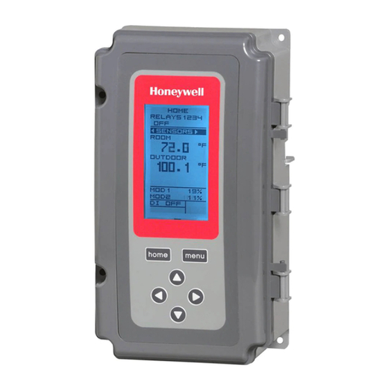
T775L Series 2000 Electronic
Stand-Alone Staging Controller
Controller Model
Description
Stage Sequencer
a
T775L2007
with Reset
a
The T775L model can be used to stage multiple relays from two independent heat or cool setpoints. The number of stages for each setpoint can
be freely chosen, limited by the number of relays available (up to 12 stages using two T775S expansion modules).
In addition to the two staged loops, up to two additional relays can be available for independent on-off control.
b
The maximum number of non-sequenced relays is two (2) with each having its own setpoint and its own throttling range. These relays are
available if not being used by the staged relay loops.
c
The T775L includes a digital input for use with the disable or setback option.
Table 1. T775L Controller Configuration.
SPDT Relay
Output Reset
Outputs
Yes
b
4
INSTALLATION INSTRUCTIONS
PRODUCT DESCRIPTION
The T775 electronic stand-alone controllers are the next
generation of commercial and agricultural controls
capable of remote sensing of temperature and providing
switched and/or proportional outputs to various types of
loads. A built-in time clock is standard.
The T775L model can be used to stage multiple relays
from two independent heat or cool setpoints. The number
of stages for each setpoint can be freely chosen, limited
only by the number of relays available.
The T775L can be configured with up to two T775S
Expansion Modules for a maximum of up to 12 stages.
IMPORTANT
The T775L is an operating control, not a limit or
safety control. If used in applications requiring
safety or limit controls, a separate safety or limit
control device is required.
Number of
Digital
Sensor
Sensors
Input
Inputs
Included
2
c
1
E4436
Stage
Addable
Control
T775S
1
Yes
Yes
62-0257-11
Enclosure
NEMA 1
Advertisement

Related Manuals for Honeywell T775L Series


Summary of Contents for Honeywell T775L Series
- Page 1 T775L Series 2000 Electronic Stand-Alone Staging Controller INSTALLATION INSTRUCTIONS PRODUCT DESCRIPTION The T775 electronic stand-alone controllers are the next generation of commercial and agricultural controls capable of remote sensing of temperature and providing switched and/or proportional outputs to various types of loads.
- Page 2 T775L SERIES 2000 ELECTRONIC STAND-ALONE STAGING CONTROLLER Temperature Sensors Accessories The controller accepts 1,097 Ohms PTC at 77°F (25°C): • 107324A – Bulb Holder, duct insertion • 50021579-001 – Standard sensor (included with all • 107408 – Heat Conductive Compound, 4 ounce models except NEMA 4X models) •...
- Page 3 T775L SERIES 2000 ELECTRONIC STAND-ALONE STAGING CONTROLLER BEFORE INSTALLATION Mount the controller on any convenient interior location using the four mounting holes provided on the back of the enclosure using #6 or #8 screws (screws are not provided Review the “Specifications” on page 37 before and must be obtained separately).
- Page 4 T775L SERIES 2000 ELECTRONIC STAND-ALONE STAGING CONTROLLER Temperature Sensor Wiring For example, in a reset control based on outside temperature, Sensor A must be the inside sensor and Sensor B must be the outside sensor. CAUTION Multiple Parallel Sensors Electrical Shock Hazard.
- Page 5 T775L SERIES 2000 ELECTRONIC STAND-ALONE STAGING CONTROLLER Controller Wiring See Fig. 7 on page 6 for locating the appropriate power input, remote sensors input, low voltage, contact closure, and load output terminals. WARNING Access to the terminals can be gained through standard conduit knockouts (A through E in Fig.
- Page 6 T775L SERIES 2000 ELECTRONIC STAND-ALONE STAGING CONTROLLER Controller Wiring Details Table 2. Description of Wiring Terminal Connections. The wiring connection terminals are shown in Fig. 7 and Terminal are described in Table 2 on page 6. Connection Label Description See Fig. 8 – Fig. 12 beginning on page 7 for typical T775L Sensors wiring applications.
- Page 7 T775L SERIES 2000 ELECTRONIC STAND-ALONE STAGING CONTROLLER SENSOR A SENSOR A (HOT) 24 VAC 120V LOAD 1 LOAD 2 LOAD 2 M24384A LOAD 1 Fig. 8. Wiring for Two-stage Control – 24 Vac Input 1 FOR 240 VAC LOAD, CONNECT TO 240 TERMINAL.
- Page 8 T775L SERIES 2000 ELECTRONIC STAND-ALONE STAGING CONTROLLER See “1.1.1.2. CALIBRATE (the sensor)” on page 13 for the instructions to enter the calibration value. See Table 3 and Fig. 13 on page 8 for temperature resistance information. Table 3. Temperature Sensor Calibration for Resistance Loss due to Wire Length.
- Page 9 T775L SERIES 2000 ELECTRONIC STAND-ALONE STAGING CONTROLLER INTERFACE OVERVIEW • Pressing and holding the MENU button for five seconds leaves the current screen and displays the Setup menu. The T775L controller uses an LCD panel and 6-button keypad to provide status information and permit user input Left and Right Arrow Buttons ( ...
- Page 10 T775L SERIES 2000 ELECTRONIC STAND-ALONE STAGING CONTROLLER Accessing the Menus • Up and Down arrow buttons ( and ) to scroll up and down through a list of items or to increase or Menus are used for setup, programming, scheduling, and decrease the value of a displayed parameter viewing the summary settings.
- Page 11 T775L SERIES 2000 ELECTRONIC STAND-ALONE STAGING CONTROLLER Setpoint High Limit for use, but in this case, relays 11 and 12 are not usable. You can set an irreversible setpoint high limit maximum • Number of relays = 8. Loop 1 uses relays 1-6, and value for any single displayed setpoint value.
- Page 12 T775L SERIES 2000 ELECTRONIC STAND-ALONE STAGING CONTROLLER Entering Setup Mode To change the controller’s sensors and output setup parameters, perform the following procedures in the order To enter Setup mode, press and hold the MENU button listed: for five seconds to display the Setup menu. See Fig. 17 1.
- Page 13 T775L SERIES 2000 ELECTRONIC STAND-ALONE STAGING CONTROLLER SETUP SETUP 1.1.1.1. UNITS (°F or °C) SENSORS SENSORS SENSOR A SENSOR A UNITS UNITS IMPORTANT DEG F This is a global change and affects the unit DEG C values for all temperature parameters on all displays.
- Page 14 T775L SERIES 2000 ELECTRONIC STAND-ALONE STAGING CONTROLLER 1.2.1. SENSOR B SETUP SETUP For two-sensor reset control, Sensor B must always be SENSORS SENSORS the controlling temperature. For example, in a reset # SENSORS control based on outside temperature, Sensor B must be SENSOR A the outside sensor.
- Page 15 T775L SERIES 2000 ELECTRONIC STAND-ALONE STAGING CONTROLLER 1.3.2. Number of LOOPS SETUP SETUP OUTPUTS OUTPUTS The value entered here determines the number of loops # LOOPS # LOOPS displayed on the home screen. 1. From the Outputs menu, highlight # LOOPS then press the ...
- Page 16 T775L SERIES 2000 ELECTRONIC STAND-ALONE STAGING CONTROLLER 1.3.3.2. MIN OFF or MIN ON SETUP SETUP SETUP OUTPUTS OUTPUTS OUTPUTS This is the minimum number of seconds of “off time” or OPTIONS OPTIONS OPTIONS MIN OFF MIN ON MIN OFF “on time” for all relays that are not configured in a loop.
- Page 17 T775L SERIES 2000 ELECTRONIC STAND-ALONE STAGING CONTROLLER SETUP SETUP 1.3.3.4. SHOW RT (show run time hours) OUTPUTS OUTPUTS OPTIONS OPTIONS 1. Press the button to display the Show RT values. SHOW RT SHOW RT 2. Use the and buttons to select YES or NO.
- Page 18 T775L SERIES 2000 ELECTRONIC STAND-ALONE STAGING CONTROLLER SETUP SETUP 1.3.4.1. Number of RELAYS OUTPUTS OUTPUTS LOOP 1 1. From the Loop 1 menu, use the and buttons to LOOP 1 # RELAYS # RELAYS highlight # RELAYS. 2. Press the button to display the number of relays.
- Page 19 T775L SERIES 2000 ELECTRONIC STAND-ALONE STAGING CONTROLLER 1.3.4.4. ON DELAY SETUP SETUP OUTPUTS OUTPUTS This is the minimum time delay between consecutive ON LOOP 1 LOOP 1 ON DELAY ON DELAY stages. This applies to all stages including the 1st stage.
- Page 20 T775L SERIES 2000 ELECTRONIC STAND-ALONE STAGING CONTROLLER SETUP SETUP 1.3.4.7. RESET (Loop Reset) OUTPUTS OUTPUTS LOOP 1 LOOP 1 This selection enables the controller’s Reset function, and RESET RESET allows each output to be individually programmed for YES-BOILER Reset or No Reset.
- Page 21 T775L SERIES 2000 ELECTRONIC STAND-ALONE STAGING CONTROLLER SETUP SETUP 1.3.5.1. SCHEDULE OUTPUTS OUTPUTS RELAY 9 RELAY 9 This selection displays only if “Use Sched = YES” is SCHEDULE SCHEDULE selected during the Output Options setup (see page 15). When selected, individual outputs default to follow the schedule.
- Page 22 T775L SERIES 2000 ELECTRONIC STAND-ALONE STAGING CONTROLLER 1.3.5.4. Exit Relay Setup SETUP Press the button to exit the selected relay set up and OUTPUTS RELAY 9 return to the Outputs menu. RESET To setup the next additional relay output go to “1.3.5.
- Page 23 T775L SERIES 2000 ELECTRONIC STAND-ALONE STAGING CONTROLLER ADDITIONAL RELAYS 2.2. Program Menu for Outputs with No LOOPS MENU MENU Reset MENU MENU PROGRAM PROGRAM PROGRAM PROGRAM From the Program menu, highlight the Loop or Relay RELAY 9 LOOP 1 RELAY 9 LOOP 1 desired and press the ...
- Page 24 T775L SERIES 2000 ELECTRONIC STAND-ALONE STAGING CONTROLLER MENU 2.2.3. SENSOR PROGRAM PROGRAM LOOP 1 LOOP 1 1. From the menu, use the and buttons to high- SENSOR SENSOR light SENSOR. SENSOR A 2. Press the button to display the sensor selections.
- Page 25 T775L SERIES 2000 ELECTRONIC STAND-ALONE STAGING CONTROLLER This completes the programming procedure for controllers that do not use Reset. 3. PROGRAMMING OUTPUT To use the Reset feature, Loop 1 must be set to Reset=YES in Setup mode (see “3.1. Setting Up the (LOOPS AND ADDITIONAL Controller for Reset”).
- Page 26 T775L SERIES 2000 ELECTRONIC STAND-ALONE STAGING CONTROLLER The remainder of this section beginning with “3.2. Entering Program Mode” describes the individual °F parameters for configuring outputs with Reset. SP MAX A1 For your reference, the following Reset programming (BOILER MAX) procedure uses the values in Fig.
- Page 27 T775L SERIES 2000 ELECTRONIC STAND-ALONE STAGING CONTROLLER MENU 3.3.1. SP MAX A1 or BOILER MAX PROGRAM PROGRAM LOOP 1 LOOP 1 (Setpoint maximum for Sensor A) SP MAX A1 SP MAX A1 1. From the menu, use the and buttons to high- light SP MAX A1.
- Page 28 T775L SERIES 2000 ELECTRONIC STAND-ALONE STAGING CONTROLLER 3.3.5. THROTTLING RANGE MENU PROGRAM PROGRAM The number of degrees selected for the throttling range is LOOP 1 LOOP 1 divided between the number of stages. See page 11 for THROT RNG THROT RNG Staged Operation.
- Page 29 T775L SERIES 2000 ELECTRONIC STAND-ALONE STAGING CONTROLLER MENU 3.4. Loop 2 MENU PROGRAM PROGRAM PROGRAM LOOP 2 For the second loop (if it is configured for Reset), the LOOP 2 LOOP 2 OFFSET Offset parameter displays on the Program menu as OFFSET shown in Fig.
- Page 30 T775L SERIES 2000 ELECTRONIC STAND-ALONE STAGING CONTROLLER MENU 3.5.1. SETPOINT OFFSET PROGRAM PROGRAM RELAY 9 RELAY 9 This value is the number of degrees plus (+) or minus (-) OFFSET OFFSET that you want the additional relay to be offset from the setpoint curve created for Loop 1.
- Page 31 T775L SERIES 2000 ELECTRONIC STAND-ALONE STAGING CONTROLLER 3.5.4. HEAT/COOL MENU PROGRAM PROGRAM 1. From the menu, use the and buttons to high- RELAY 9 RELAY 9 light HEAT/COOL. HEAT/COOL HEAT/COOL Default: HEAT HEAT 2. Press the button to display the heat and cool COOL selections.
- Page 32 T775L SERIES 2000 ELECTRONIC STAND-ALONE STAGING CONTROLLER Creating a Schedule NOTES: If you press the HOME button or there is no To create a schedule, perform the following in the order keypad activity for four minutes, you exit listed: Schedule mode and return to the home 1.
- Page 33 T775L SERIES 2000 ELECTRONIC STAND-ALONE STAGING CONTROLLER 5. Press the button to accept the Time and return to the Options menu. MAIN MAIN 4.2.2. SET DATE SCHEDULE SCHEDULE OPTIONS OPTIONS Setting the system date is required to enable the...
- Page 34 T775L SERIES 2000 ELECTRONIC STAND-ALONE STAGING CONTROLLER Setpoint time span is 6:00 AM until 5:59 PM because setback starts at 6:00 PM. Setback time span is 6:00PM until 5:59 AM because setpoint starts at 6:00 AM. To set a schedule, continue with “4.3.1. E1 SETPT (setpoint for event 1)”.
- Page 35 T775L SERIES 2000 ELECTRONIC STAND-ALONE STAGING CONTROLLER 4.4. Exiting Scheduling Mode This completes the Scheduling procedure. Press the HOME button to exit the Schedule menu and return to the home screen display. 62-0257—11...
- Page 36 T775L SERIES 2000 ELECTRONIC STAND-ALONE STAGING CONTROLLER SUMMARY MENU TROUBLESHOOTING The Summary menu provides the ability to view the Power Loss schedule (E1 and E2 times) for each relay for each day of the week. The date and time settings are retained for 24 hours after a power outage.
- Page 37 T775L SERIES 2000 ELECTRONIC STAND-ALONE STAGING CONTROLLER SPECIFICATIONS Power: 24, 120, or 240 Vac; 50/60 Hz; Emissions Compliance A separate earth ground is required for any power EN 55022: 2006 source. CISPR 22: 2006 VCCI V-3/2006.04 Power Consumption: ICES-003, Issue 4: 2004 •...
- Page 38 T775L SERIES 2000 ELECTRONIC STAND-ALONE STAGING CONTROLLER 62-0257—11...
- Page 39 T775L SERIES 2000 ELECTRONIC STAND-ALONE STAGING CONTROLLER 62-0257—11...
- Page 40 T775L SERIES 2000 ELECTRONIC STAND-ALONE STAGING CONTROLLER Automation and Control Solutions Honeywell International Inc. 1985 Douglas Drive North Golden Valley, MN 55422 Honeywell Limited-Honeywell Limitée 35 Dynamic Drive ® U.S. Registered Trademark Toronto, Ontario M1V 4Z9 © 2009 Honeywell International Inc.