Advertisement
Quick Links
Controller Power Supply
Document Number
Summary
Enclosed is a new Power Supply module for your ControlEdge HC900
Controller.
It can be installed in a:
Contents
Installation
Guidelines
June 2018
ControlEdge HC900 Controller
Power Supply Module
Installation and Replacement
Form: 51-52-33-129
Effective Date: 06/2018
Supersedes: 11/2005
Standard Controller or Remote I/O Rack Assembly – Figure 1
I/O Rack Assembly with Redundant Power – Figure 2
(Only available on 8 slot and 12 slot I/O Racks)
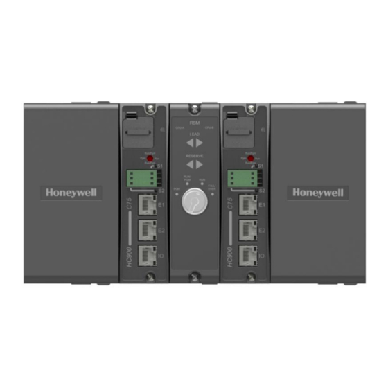
Redundant Controller Rack Assembly – Figure 3
WARNING
Never attempt to remove the Power Supply module from
the controller rack with power applied.
The power supply module is supplied in a shipping container and
protective shipping materials. The container includes an appropriate
identification label that matches the label on the module. The Power
Supply module should be stored in the shipping container until ready for
installation.
The power supply module may only be inserted into a dedicated slot
location in the rack as shown in Figure 1, 2, or 3. The safety ground
connection of the field power source must be connected to the chassis
ground terminal. The power supply ground jumper also connects to the
chassis safety ground terminal. See Figure 4 or Figure 5.
Power Supply Module Kit # 51-52-33-129
900P01 - (current revision number)
900P24 - (current revision number)
RIUP
1
Advertisement

Related Manuals for Honeywell 900P01


Summary of Contents for Honeywell 900P01
- Page 1 ControlEdge HC900 Controller Power Supply Module Installation and Replacement Controller Power Supply 900P01 - (current revision number) 900P24 - (current revision number) Document Number Form: 51-52-33-129 Effective Date: 06/2018 Supersedes: 11/2005 Summary Enclosed is a new Power Supply module for your ControlEdge HC900 Controller.
-
Page 2: Power Supply Module
Power Supply Module Power Supply Module Controller or Scanner CPU Module Slot Controller or Scanner CPU Module Slot Figure 1 – Power Supply in a Controller or Remote I/O rack 1 – Power Status Module Slot 1 – Power Status Module Slot 2 –... - Page 3 Figure 3–P01 Power Supply in a Redundant Controller Rack June 2018 Power Supply Module Kit # 51-52-33-129...
- Page 4 Remove the Power Supply from its shipping container and insert it into the slot location in the rack as shown in Figure 1, 2, or 3. Orient the module to have the Honeywell Logo on the top. Push the power supply module into the slot until the rear connector engages the mating connector of the rack backplane.
- Page 5 Figure 4– P01 Safety Ground Connections Figure 5– P24 Safety Ground Connections June 2018 Power Supply Module Kit # 51-52-33-129...