Advertisement
Quick Links
Installing the Device
•
•
•
•
•
Unpacking the Device
The device, accessory kit, publications, and any optional units may be shipped in more than one container.
When you unpack the containers, check the packing list to ensure that you have received all the items on the
list.
Only unpack the product when you are ready to install it. This will help prevent accidental damage.
Locating the Product ID, Serial Number, Version ID and Common
Language Equipment Identifies (CLEI)
The serial number (SN), product ID (PID), version ID (VID), and Common Language Equipment Identifier
(CLEI) are printed on a label on the label tray located on the server chassis or motherboard.
Unpacking the Device, on page 1
Locating the Product ID, Serial Number, Version ID and Common Language Equipment Identifies
(CLEI), on page 1
Installing the Cisco 5400 ENCS, on page 2
Powering On the Server, on page 5
Initial Server Setup, on page 6
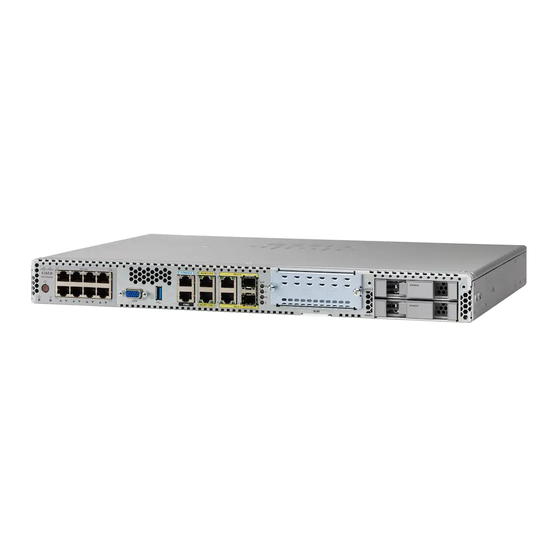
Installing the Device
1
Advertisement

Related Manuals for Cisco 5400 Series


Summary of Contents for Cisco 5400 Series
- Page 1 • Locating the Product ID, Serial Number, Version ID and Common Language Equipment Identifies (CLEI), on page 1 • Installing the Cisco 5400 ENCS, on page 2 • Powering On the Server, on page 5 • Initial Server Setup, on page 6 Unpacking the Device The device, accessory kit, publications, and any optional units may be shipped in more than one container.
-
Page 2: Rack-Mounting The Chassis
NIM and HDDs either before or after you mount the chassis. Rack-Mounting the Chassis The Cisco 5400 ENCS can be installed in 19-inch (48.26-cm) racks. Use the standard brackets shipped with the router for mounting the chassis in a 19-inch EIA rack. - Page 3 Installing the Device Rack-Mounting the Chassis Figure 2: Bracket Installation for Front Mounting Figure 3: Bracket Installation for Back Mounting Mounting the device in a Rack After you attach the brackets to the device, install the chassis on the rack as shown in Figure 8. You will need two screws to attach each bracket to the rack;...
-
Page 4: Wall-Mounting The Chassis
Installing the Device Wall-Mounting the Chassis Figure 4: Mounting the Chassis on the Rack - Front and Back The screw slots in the brackets are spaced to line up with every second pair of screw holes in the rack. When the correct screw holes are used, the small threaded holes in the brackets line up with unused screw holes in the rack. -
Page 5: Powering On The Server
Installing the Device Powering On the Server Figure 5: Wall Mounting the Server Powering On the Server Note When the power cord is connected to the system, both the management controller (CIMC) and the server is automatically powered on. When the system is powered on, do not press the front-panel power button. If you press the front-panel power button, it will power off the server, but the management controller (CIMC) continues to be operational. -
Page 6: Initial Server Setup
Installing the Device Initial Server Setup Initial Server Setup Local Connection Procedure 1. Ensure that the device is powered on. 2. Connect a keyboard and a monitor to the corresponding ports on the front panel of the device. 3. When you see the prompt, you can do the following: •...