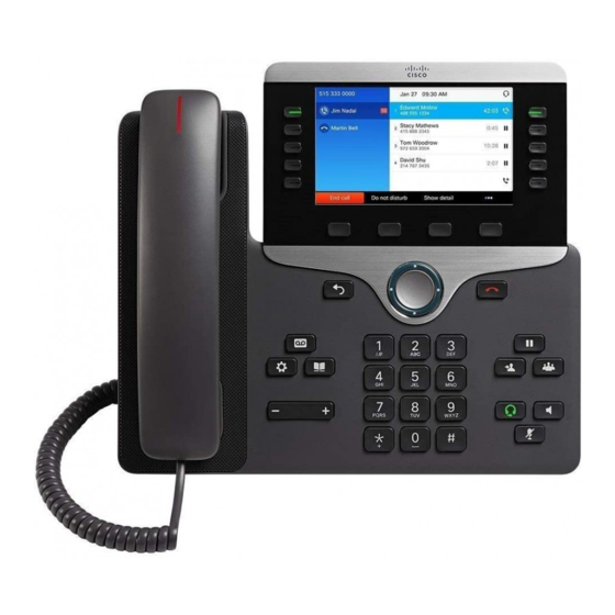
Cisco 8800 Series Manual
Add buttons to your phone
Hide thumbs
Also See for 8800 Series:
- Manual (544 pages) ,
- Administration manual (406 pages) ,
- User manual (218 pages)
Advertisement
Quick Links
Add Buttons to Your Phone (8800 Series)
•
•
•
•
•
•
•
Cisco IP Phone 8800 Key Expansion Module
A key expansion module allows you to add extra line appearances or programmable buttons to your phone.
The programmable buttons can be set up as phone line buttons, speed-dial buttons, or phone feature buttons.
Simplified dialing is not supported on the expansion modules.
The following table describes the number of Key Expansion Modules supported by each model in the Cisco
IP Phone 8800 Series.
Table 1: Key Expansion Module Support
Cisco IP Phone Model
8851 and 8851NR
8861, 8865, and 8865NR
When multiple key expansion modules are attached to the phone, they are numbered according to the order
in which they are connected to the phone. For example:
• Key expansion module 1 is the closest unit to the phone.
• Key expansion module 2 is the unit in the middle.
• Key expansion module 3 is the farthest unit from the phone.
Cisco IP Phone 8800 Key Expansion Module, on page 1
Key Expansion Module Buttons and Hardware, on page 2
Manage Your Key Expansion Modules, on page 12
Place a Call on the Key Expansion Module, on page 13
Number of Key Expansion Modules Supported
2 key expansion modules with 72 buttons
3 key expansion modules with 108 buttons
Add Buttons to Your Phone (8800 Series)
1
Advertisement

Summary of Contents for Cisco 8800 Series
-
Page 1: Table Of Contents
The programmable buttons can be set up as phone line buttons, speed-dial buttons, or phone feature buttons. Simplified dialing is not supported on the expansion modules. The following table describes the number of Key Expansion Modules supported by each model in the Cisco IP Phone 8800 Series. -
Page 2: Key Expansion Module Buttons And Hardware
Add Buttons to Your Phone (8800 Series) Key Expansion Module Buttons and Hardware Figure 1: Cisco IP Phone 8861 with Three Cisco IP Phone 8800 Key Expansion Modules Caution The slots in the side of the phone are designed only for use with the spine connectors on the key expansion module. - Page 3 Add Buttons to Your Phone (8800 Series) Key Expansion Module Buttons and Hardware Lighted buttons—18 buttons. If the feature on the button is the line feature, that button corresponds to one line (same as on the phone). The lights beneath each button indicate the state of the corresponding line as follows: •...
-
Page 4: Connect A Key Expansion Module To A Cisco Ip Phone
Add Buttons to Your Phone (8800 Series) Connect a Key Expansion Module to a Cisco IP Phone Connect a Key Expansion Module to a Cisco IP Phone If you want to install more than one key expansion module, you repeat steps 7-9 to connect the other key expansion modules together. - Page 5 Position the phone so that the front of the phone faces up. Step 6 Connect one end of the key expansion module spine connector to the accessory connector on the Cisco IP Phone. a) Align the spine connector with the accessory connector ports.
- Page 6 Add Buttons to Your Phone (8800 Series) Connect a Key Expansion Module to a Cisco IP Phone Step 7 Connect the other end of the spine connector to the key expansion module as shown in this diagram. a) Align the spine connector with the key expansion module accessory connector ports.
- Page 7 Add Buttons to Your Phone (8800 Series) Connect a Key Expansion Module to a Cisco IP Phone Step 8 (Optional) Use a second key expansion module spine connector to connect the second key expansion module to the first key expansion module.
-
Page 8: Connect Two Or Three Key Expansion Modules To A Cisco Ip Phone
Add Buttons to Your Phone (8800 Series) Connect Two or Three Key Expansion Modules to a Cisco IP Phone Note Make sure that the screws are fully inserted into the phone and tightened. If you lose any screws, the phone uses a standard M3 0.5x5.0mm screw. - Page 9 Position the phone so that the front of the phone faces up. Step 6 Connect one end of the key expansion module spine connector to the accessory connector on the Cisco IP Phone. a) Align the spine connector with the accessory connector ports.
- Page 10 Add Buttons to Your Phone (8800 Series) Connect Two or Three Key Expansion Modules to a Cisco IP Phone This diagram shows the spine connector. This diagram shows the installation of the spine connector. Step 7 Connect the other end of the spine connector to the key expansion module as shown in this diagram.
- Page 11 Step 9 Use a third key expansion module spine connector to connect the third key expansion module to the second (middle) key expansion module. This figure shows a Cisco IP Phone with three key expansion modules attached. Step 10 Use a screwdriver to fasten the screws into the phone and into each key expansion module.
-
Page 12: Manage Your Key Expansion Modules
Manage Your Key Expansion Modules After you install and set up a key expansion module on your phone, the device automatically gets added to My Cisco Spark. Here, you can perform any number of actions: • View the status of a device. -
Page 13: Place A Call On The Key Expansion Module
Add Buttons to Your Phone (8800 Series) Place a Call on the Key Expansion Module Place a Call on the Key Expansion Module Procedure Step 1 Press the line button on the key expansion module. Step 2 Dial a phone number. - Page 14 Add Buttons to Your Phone (8800 Series) Adjust the Key Expansion Module Screen Brightness Add Buttons to Your Phone (8800 Series)


