Advertisement
Quick Links
INSTALLATION INSTRUCTIONS FOR THE
HAZARDOUS LOCATION BASIC SWITCHES
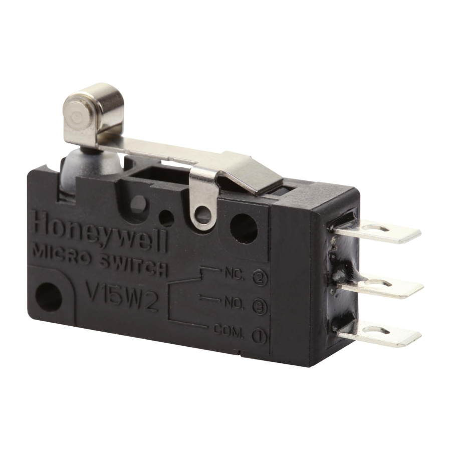
MICRO SWITCH V15W2 SWITCHES
m WARNING
PERSONAL INJURY WARNING
DO NOT USE these products as safety or emergency stop
devices or in any other application where failure of the
product could result in personal injury.
Failure to comply with these instructions could result in
death or serious injury.
, CAUTION
SWITCH DAMAGE
•
Wiring must be rated to meet or exceed circuitry
requirements.
•
Connecting circuitry must not exceed switch rating.
•
Wiring connections must be properly secured.
•
Do not exceed recommended soldering time or
temperature.
•
Do not contact switch housing with soldering device.
•
Do not exceed recommended mounting screw
tightening torques.
•
Discontinue use if switch has been damaged or cover
removed.
•
Do not apply side loads to actuator or exceed specified
travel limits.
•
Do not operate or store in areas where corrosive gases
such as hydrogen sulfide are present.
Failure to comply with these instructions could result in
death or serious injury.
GENERAL INFORMATION
MICRO SWITCH V15W2 basic switches are precision snap-
action contact mechanisms enclosed in plastic cases. Switch
actuation triggers the mechanical closure of the switch's
contacts. The switches are approved for use in Zone 2
hazardous locations. While a small amount of arcing occurs
between the switch contacts during contact closure, the
switch is environmentally sealed so that flammable gases
cannot enter into the switching cavity. This mimimizes the
chances of ignition of flammable gases in a hazardous
atmosphere. The IEC Ex approvals are as such:
Ex nC IIA T5 Gc for an ambient temperature range of
-25°C to +85°C per IEC 60079-0 6
IEC 60079-15 4
Edition (2010) via certificate IEC Ex
th
DEK 17.0053U.
The ATEX approval are as such: II 3 G Ex nC IIA T5 Gc per
EN 60079-0 : 2012 + A11 : 2013 and EN 60079-15 : 2010
via ATEX certificate DEKRA 19ATEX0013 U
Edition (2011) and
th
TABLE 1. MOUNTING INFORMATION
Mounting
Screw type*
hole size
Flat fillister
3,1 mm
head
2,9 mm
Flat fillister
(-K option)
head
*To prevent loosening of screws, use spring washers under
screw heads and thread lock adhesive.
•
Turn OFF the power supply before mounting or removing
the switch, wiring, or performing maintenance or
inspection. Failure to do so may result in electric shock.
•
Switch must be mounted in an enclosure to prevent
contact to live electrical parts and to protect the switch
from exposure to ultraviolet light.
•
Mount the switch onto a flat surface. Mounting on an
uneven surface may cause deformation of the switch,
resulting in faulty operation or damage.
•
Use an operating device with low frictional resistance
and of a shape that will not interfere with the plunger
seal, otherwise the plunger may be damaged or the
sealing may deteriorate.
•
Position the operating device perpendicular to the
actuator/pushbutton to prevent side loading of the
switch actuator or pushbutton.
•
Position the operating device so that no force is applied
to the pushbutton/actuator when the switch is in the free
position.
•
The operating device should be positioned so that when
the switch is in the operating position it should move the
actuator no less than 70 % of the total travel. Setting the
travel position so that less than 70 % of the total travel is
used may cause poor contact or welding conditions due
to an insufficient contact switching force.
•
The operating device should never force the actuator/
pushbutton to exceed the total travel position.
WIRING INFORMATION
•
Connect wires firmly to terminals.
•
Replace wires that have damaged insulation.
•
Use properly sized receptacles.
•
Use wire rated for the application's electrical load and
application's temperature.
•
Provide strain relief when a potential exists for forces to
be transferred from the lead wires to the switch terminals.
32333029
Issue E
Tightening
Screw size
torque (max.)
4,5 kg-cm
3 mm
[3.9 in-lb]
4,5 kg-cm
#4
[3.9 in-lb]
Advertisement

Related Manuals for Honeywell V15W2 Series


Summary of Contents for Honeywell V15W2 Series
- Page 1 32333029 INSTALLATION INSTRUCTIONS FOR THE HAZARDOUS LOCATION BASIC SWITCHES Issue E MICRO SWITCH V15W2 SWITCHES m WARNING TABLE 1. MOUNTING INFORMATION PERSONAL INJURY WARNING Mounting Tightening Screw type* Screw size hole size torque (max.) DO NOT USE these products as safety or emergency stop devices or in any other application where failure of the Flat fillister 4,5 kg-cm...
- Page 2 350 °C [662 °F]. Contacting the switch If warranted goods are returned to Honeywell during the period of coverage, Honeywell will repair or replace, at its housing with the soldering device may damage the switch option, without charge those items that Honeywell, in its sole housing.