
Related Manuals for Lanner R3S


Summary of Contents for Lanner R3S
- Page 1 R3S User Manual Vehicle Computing User Manual Version: 1.0 Date of Release: 2020-09-03...
- Page 2 R3S User Manual Icon Descriptions The icons are used in the manual to serve as an indication of interest topics or important messages. Below is a description of these icons: Note: This mark indicates that there is a note of interest and is something that you should pay special attention to while using the product.
- Page 3 R3S User Manual Acknowledgement Intel® , Intel® Atom® are trademarks or registered trademarks of Intel Corporation or its subsidiaries in the U.S. and/or other countries. Microsoft Windows and MS-DOS are registered trademarks of Microsoft Corp. All other product names or trademarks are properties of their respective owners.
- Page 4 R3S User Manual Keep the chassis area clear and dust-free during and after installation. Do not wear loose clothing or jewelry that could get caught in the chassis. Fasten your tie or scarf and roll up your sleeves. Wear safety glasses if you are working under any conditions that might be hazardous to your eyes.
- Page 5 R3S User Manual Avertissement concernant la pile au lithium Risque d’explosion si la pile est remplacée par une autre d’un mauvais type. Jetez les piles usagées conformément aux instructions. L’installation doit être effectuée par un électricien formé ou une personne formée à...
- Page 6 Lanner Electronics Inc. shall not be held liable for any losses resulting from insufficient strength for supporting the system or use of inappropriate installation components.
- Page 7 R3S User Manual Grounding Procedure for Power Source Loosen the screw of the earthing point. Connect the grounding cable to the ground. The protection device for the power source must provide 30 A current. This protection device must be connected to the power source before power.
-
Page 8: Table Of Contents
R3S User Manual Table of Contents Package Content....................... 10 Ordering Information ....................10 System Specifications ....................11 Front Panel ....................... 13 Rear Panel ........................ 14 Motherboard Information..................16 Open the Chassis ...................... 24 Installing the M.2 LTE Module ................. 25 Hard Disk Installation .................... - Page 9 R3S User Manual Using the Ignition System Manager (ISM) ............... 56 Warranty Policy ......................58 RMA Service ......................58 RMA Service Request Form ..................59...
-
Page 10: Package Content
EN50155, EN50121-3-2, EN50121-4, EN50125-3 and EN45545 standard as an IP50 rated fanless rolling stock computer. R3S not only features high-performance Intel Atom x7-E3950 CPU, but also boasts an abundance of I/O and internal expansion capabilities, including 6 x M12 X- coded PoE/ PoE+ ports, 1 x Removable 2.5”... -
Page 11: System Specifications
R3S User Manual System Specifications Intel Apollo Lake x7-E3950 1.6G 12W 1.6 GHz Frequency Platform AMI SPI Flash BIOS BIOS Chipset Fanless LPDDR4 2400 MHz Technology Memory Up to 8GB (Factory default: 8GB pre-populated) Max. Capacity Memory Down Socket 6x Intel i210IT... - Page 12 R3S User Manual IP rated 50, MIL-STD-810G, EN50155, EN50121-3-2, EN50121- Certified 4, EN50125-3, EN 45545 Fintek F81866AD-I integrated watchdog timer Hardware Miscellaneous Internal with Battery...
-
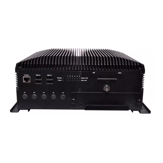
Page 13: Front Panel
R3S User Manual Front Panel Description System Status System Power Status System Status LED Indicator HDD Status USB 2.0 Port 4x USB 2.0 Type A 1x RS-232 (RJ45 connector) Console Port Signals Signals COM_RTS1# COM_DTR1# COM_SOUT1 GND_COM GND_COM COM_SIN1 COM_DSR1#... -
Page 14: Rear Panel
R3S User Manual Rear Panel ˇ ˋ ˇ Grounding Point: For safety measures to help prevent people from accidentally coming in contact with electrical hazards. Description PoE Port 6x M12 X-coded 8-pin PoE/ PoE+ Port Signals Signals LANx*_MX0P LANx*_MX0N LANx*_MX1P... - Page 15 R3S User Manual 2x DB9 Male Connector for RS232/422/485 Signals Signals 1_up COM2_C_DCD_TN 2_up COM2_C_RXD_TP 3_up COM2_C_TXD_RP 4_up COM2_C_DTR_RN 5_up GND_COM 6_up COM2_C_DSR COM Port 7_up COM2_C_RTS 8_up COM2_C_CTS 9_up COM2_C_RI 1_down COM3_C_DCD_TN 2_down COM3_C_RXD_TP 3_down COM3_C_TXD_RP 4_down COM3_C_DTR_RN 5_down...
-
Page 16: Motherboard Information
R3S User Manual Motherboard Information Block Diagram... - Page 17 R3S User Manual Motherboard Layout The motherboard layout shows the connectors and jumpers on the board. Refer to the following picture as a reference for the pin assignments and the internal connectors. Front ...
- Page 18 R3S User Manual Back...
- Page 19 R3S User Manual Jumper setting and Internal Connector...
- Page 20 R3S User Manual...
- Page 21 R3S User Manual...
- Page 22 R3S User Manual Motherboard Layout (RIO3SB1) Front Back ...
- Page 23 R3S User Manual Jumper setting and Internal Connector (RIO3SB1)
-
Page 24: Open The Chassis
R3S User Manual To reduce the risk of personal injury, electric shock, or damage to the unit, please remove all power connections to completely shut down the device. Also, please wear ESD protection gloves when conducting the steps in this chapter. -
Page 25: Installing The M.2 Lte Module
R3S User Manual Installing the M.2 LTE Module 1. Locate M.2 slot. Align the notch of the module with the socket key in the slot, and insert it at 30 degrees into the socket until it is fully seated in the connector. -
Page 26: Hard Disk Installation
R3S User Manual Push the SIM cards into the socket. Make sure the angled corner of the card is positioned correctly as shown in this picture. To remove the card, simply push it to have it bounce out automatically. Hard Disk Installation To install the hard disk, 1. - Page 27 R3S User Manual 5. Connect the SATA cable and lock the drive in place with screws. Reverse Step 1~ Step 3 to lock the disk tray into the chassis.
-
Page 28: Bios Setup
R3S User Manual BIOS Setup BIOS is a firmware embedded on an exclusive chip on the system’s motherboard. Lanner's BIOS firmware offering including market-proven technologies such as Secure Boot and Intel Boot Guard technology deliver solid commitments for the shield protection against malware, uncertified sequences and other named cyber threats. - Page 29 R3S User Manual Setup main page contains BIOS information and project version information. Feature Description BIOS Vendor: American Megatrends Core Version: AMI Kernel version, CRB code base, X64 Compliancy: UEFI version, PI version BIOS Information Project Version: BIOS release version...
-
Page 30: Advanced Page
R3S User Manual ■ Select the Advanced menu item from the BIOS setup screen to enter the “Advanced” setup screen. Users can select any of the items in the left frame of the screen. - Page 31 R3S User Manual ■...
- Page 32 R3S User Manual ■ Feature Options Description Enabled Serial Port Enables or disables Serial Port 1. Disabled IO=3F8h; IRQ = 4 Serial Port 1 Device Settings IO=2F8h; IRQ = 11 Serial Port 2 RS232 COM mode RS485 Configure COM port mode.
- Page 33 R3S User Manual ■ Feature Options Description Enabled Serial Port Enables or disables Serial Port 3 ~ 6. Disabled Device Settings Assigned to IO=3E8h; IRQ = 5...
- Page 34 R3S User Manual ■ Feature Description CPU Temp This value reports the CPU temperature. SYS Temp This value reports the System temperature. VCORE This value reports the CPU VCORE. Vddr This value reports the Vddr. VBAT This value reports the VBAT Input voltage.
- Page 35 R3S User Manual ■ Feature Options Description Watch Dog Timer Enabled Enable or Disable Watch Dog function Disabled Timer Count Mode Second Mode Select Second Mode or Minute Mode Minute Mode Timer out Value Watch Dog Timer out Value 0-255...
- Page 36 R3S User Manual ■ Feature Options Description SIM-1 SIM Selector1 Select which SIM card would use SIM-2 SIM Selector2 SIM-3 Select which SIM card would use SIM-4...
- Page 37 R3S User Manual ■ Feature Options Description COM0 Enabled Console Redirection Enable or Disable. Console Disabled Redirection...
- Page 38 R3S User Manual ■ Feature Options Description Terminal Type VT100 ANSI: Extended ASCII char set. VT100+ VT100: ASCII char set. VT-UTF8 VT100+: Extends VT100 to support color, ANSI function keys, etc. VT-UTF8: Uses UTF8 encoding to map Unicode chars onto 1 or more bytes.
- Page 39 R3S User Manual data packet. Flow Control None Flow control can prevent data loss from Hardware RTS/CTS buffer overflow. VT-UTF8 Combo Key Disabled Enable VT-UTF8 Combination Key Support Enabled Support for ANSI/VT100 terminals Recorder Mode Disabled With this mode enabled only text will be Enabled sent.
- Page 40 R3S User Manual ■ Feature Options Description Intel Virtualization Disabled When enabled, a VMM can utilize the Technology Enabled additional hardware capabilities provided by Vanderpool Technology VT-d Disabled Enable/Disable CPU VT-d Enabled...
- Page 41 R3S User Manual ■...
- Page 42 R3S User Manual ■ Feature Options Description Globally Enables or Disables 64bit capable Devices Above 4G Disabled to be Decoded in Above 4G Address Space (Only Decoding Enabled if System Supports 64 bit PCI Decoding). Re-enable Bus Master Attribute disabled during...
- Page 43 R3S User Manual ■ Feature Options Description Disabled CSM Support Enables or disables CSM Support Enabled Do Not Launch Controls the execution of UEFI and Network UEFI Legacy PXE OpROM Legacy Do Not Launch Controls the execution of UEFI and...
- Page 44 R3S User Manual ■ Feature Options Description Enables Legacy USB support. Enabled Auto option disables legacy support if no USB Legacy USB Support Disabled devices are connected;; Disabled option will keep Auto USB devices available only for EFI applications. This is a workaround for OSes without XHCI hand-...
-
Page 45: Intelrcsetup
R3S User Manual IntelRCSetup Select the IntelRCSetup menu item from the BIOS setup screen to enter the Platform Setup screen. Users can select any of the items in the left frame of the screen. - Page 46 R3S User Manual ■ Feature Options Description 2 GB 2.25 GB Max TOLUD 2.5 GB Maximum Value of TOLUD. 2.75 GB 3 GB...
- Page 47 R3S User Manual ■ Feature Options Description Windows Android OS Selection Select the target OS Win7 Intel Linux...
- Page 48 R3S User Manual ■...
-
Page 49: Security
R3S User Manual Security Select the Security menu item from the BIOS setup screen to enter the Security Setup screen. Users can select any of the items in the left frame of the screen. Feature Description If ONLY the Administrator's password is set, it only limits access to Setup and is only asked for when entering Setup. -
Page 50: Boot Menu
R3S User Manual Boot Menu Select the Boot menu item from the BIOS setup screen to enter the Boot Setup screen. Users can select any of the items in the left frame of the screen. Feature Options Description The number of seconds to wait for setup Setup Prompt Timeout activation key. -
Page 51: Save And Exit Menu
R3S User Manual Save and Exit Menu Select the Save and Exit menu item from the BIOS setup screen to enter the Save and Exit Setup screen. Users can select any of the items in the left frame of the screen. - Page 52 R3S User Manual ■ Save Changes and Reset When Users have completed the system configuration changes, select this option to save the changes and reset from BIOS Setup in order for the new system configuration parameters to take effect. The following window will appear after selecting the “Save Changes and Reset”...
- Page 53 R3S User Manual The status explanations of LED indicators on Front Panel are as follows: HDD Activity Status Blinking Amber Data access activities No data access activities System Power Solid Green The system is powered on The system is powered off...
-
Page 54: Connecting The Devices
R3S User Manual Connecting the Devices The system comes with a controller to ensure that the device is well-shielded against premature failure at the boot or shutdown phase. When installing: 1. Make sure both your vehicle and the system are turned off. -
Page 55: Power States Cycle Diagram
R3S User Manual Power States Cycle Diagram The diagram below describes the cycle of system’s power states controlled by the Ignition System Manager (ISM) when the appropriate timer control parameters are set. (by ISM tool) System OS Running Ignition board supplies... -
Page 56: Using The Ignition System Manager (Ism)
R3S User Manual Using the Ignition System Manager (ISM) Command Format: 1. Host communication interface: COM#6 (RS-232) 2. Support buad rate: 57600/ 8N1 3. Communication protocol: ANSI terminal. GET VariableName SET VariableName value... - Page 57 R3S User Manual Example:...
-
Page 58: Warranty Policy
R3S User Manual Warranty Policy 1. All products are under warranty against defects in materials and workmanship for a period of one year from the date of purchase. 2. The buyer will bear the return freight charges for goods returned for repair within the warranty period;... -
Page 59: Rma Service Request Form
R3S User Manual RMA Service Request Form When requesting RMA service, please fill out the following form. Without this form enclosed, your RMA cannot be processed.