
Related Manuals for Lanner V3S


Summary of Contents for Lanner V3S
- Page 1 V3S User Manual Vehicle Computing User Manual Version: 1.6 Date of Release: 2020-11-27...
- Page 2 Warning: This mark indicates that there is a caution or warning, and it is something that could damage your property or product. Online Resources The listed websites are links to online product information and technical support. Resources Lanner http://www.lannerinc.com Product Resource http://www.lannerinc.com/download- center http://eRMA.lannerinc.com...
- Page 3 V3S User Manual Compliances and Certification This product has passed the CE test for environmental specifications. Test conditions for passing included the equipment being operated within an industrial enclosure. To protect the product from being damaged by ESD (Electrostatic Discharge) and EMI leakage, we strongly recommend using CE-compliant industrial enclosure products.
- Page 4 Consignes de sécurité Suivez ces consignes pour assurer la sécurité générale : Laissez la zone du châssis propre et sans poussière pendant et après l’installation. Ne portez pas de vêtements amples ou de bijoux qui pourraient être pris dans le châssis. Attachez votre cravate ou écharpe et remontez vos manches.
- Page 5 V3S User Manual Operating Safety Electrical equipment generates heat. Ambient air temperature may not be adequate to cool equipment to acceptable operating temperatures without adequate circulation. Be sure that the room in which you choose to operate your system has adequate air circulation.
- Page 6 The installation of this product must be performed by trained specialists; otherwise, a non-specialist might create the risk of the system’s falling to the ground or other damages. Lanner Electronics Inc. shall not be held liable for any losses resulting from insufficient strength for supporting the system or use of inappropriate installation components.
- Page 7 V3S User Manual Grounding Procedure for Power Source Loosen the screw of the earthing point. Connect the grounding cable to the ground. The protection device for the power source must provide 30 A current. This protection device must be connected to the power source before power.
-
Page 8: Table Of Contents
Table of Contents Package Content ......................... 10 Ordering Information ......................... 11 System Specifications ......................... 12 Front Panel ..........................13 Rear Panel ........................... 14 Block Diagram ..........................15 Motherboard Layout ........................16 Internal Jumpers & Connectors ....................17 Enter BIOS Setup ........................23 Advanced ............................ - Page 9 V3S User Manual Warranty Policy .......................... 68 RMA Service ..........................68 RMA Service Request Form ......................69...
-
Page 10: Package Content
Atom™ processors. V3S boasts an abundance of I/O peripheral connectivity, including 2 x serial COM ports, 2x video output by DVI-D, USB and Digital I/O ports, 6x RJ-45 ports (4 with PoE), and removable SATA storage bay. To enable wireless network connectivity, V3S offers two mini-PCIe sockets with a swappable dual SIM slot supporting 3G/4G/LTE cellular communications and optional removable PGN Caddy with dual SIM card readers. -
Page 11: Ordering Information
V3S User Manual Ordering Information SKU No. Description Fanless In-vehicle Surveillance Computer with Intel® Atom™ x7-E3950 Processor, V3SA IEEE 802.3af PoE ports RJ45 x4 Fanless In-vehicle Surveillance Computer with Intel® Atom™ x7-E3950 Processor, V3SB IEEE 802.3af PoE/ at PoE+ ports RJ45 x4... -
Page 12: System Specifications
System Specifications Intel® Atom™ x7-E3950 Frequency 1.60 GHz Processor System Core Number Chipset Fanless Technology 1x DDR3L 1866 SO-DIMM Socket Memory Max. Capacity Up to 8GB Socket 1x 204-pin SODIMM Graphic Graphic Processor Intel® Integrated HD Graphics 505 Codec Realtek ALC886 HD codec Audio Interface Mic-in and Line-out... -
Page 13: Front Panel
V3S User Manual Front Panel Description Key Lock For extra protection of the data on the hard disk Indicating the status of 4x PoE port LED Indicators PoE 1 2 3 4 (PoE Ports) (Please refer to Appendix A: LED Indicator Explanations) -
Page 14: Rear Panel
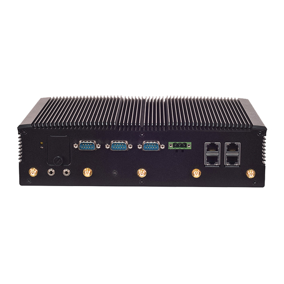
Rear Panel PoE1 PoE3 PoE4 Mic-in Line-out Description 5x Antenna Port Antenna Port From left to right: WiFi WiFi GPS WiFi WiFi Reset Button Press to reset the system For 2x SIM cards Dual SIM Socket 1x DB9 Male connector for CAN Bus CAN Bus Port COM Port 2x DB9 Male Connector for RS232/422/485... -
Page 15: Block Diagram
V3S User Manual Block Diagram The block diagram indicates how data flows among components on the motherboard. Please refer to the following figure for your motherboard’s layout design. -
Page 16: Motherboard Layout
Motherboard Layout This layout shows the connectors and jumpers on the board regarding the pin assignments and the internal connectors. -
Page 17: Internal Jumpers & Connectors
V3S User Manual Internal Jumpers & Connectors ▲CAN1 Pin Signal J1850-/J1708- GND_COM CAN_H/J1939+ K_LINE CAN_L/J1939- J1850-/J1708- J1850+/J1708+ J1850+/J1708+ BAT_12V_24V ▲ PRJK1: (+9V~36V) Pin Signal IGNITION GND_IGNI DC_VIN ▲ SW2 Pin Signal Function ON (Default) For detection of power status Enabling low power detection... - Page 18 ▲ JCOM1 Pin Signal IGN3V3_SB NXP_RXD NXP_TXD ▲ JCOMS1 Pin Signal VCCRTC_3P3 ▲ JCOMS2 Pin Signal RTEST_N ▲ JRI1 1-2 (Default) COM1 Pin Signal COM_RI1#_P COM_RI1#_SEL V5_S COM_RI1#_SEL V12_S COM_RI1#_SEL ▲ JRI2 1-2 (Default) COM2 Pin Signal COM_RI2#_P COM_RI2#_SEL V5_S COM_RI2#_SEL V12_S COM_RI2#_SEL...
- Page 19 V3S User Manual ▲ JSPI1 Signal SPI0_HOLD_N SPI0_CS_N V1P8_A_SPI SPI0_MISO_R SPI0_CLK SPI0_MOSI ▲ LPC1 Signal L_CLKOUT1 LPC_AD1 PLTRST_BUF2_N LPC_AD0 LPC_FRAME# V3P3_S LPC_AD3 LPC_AD2 ▲ AUDIO1 Signal MIC_OUT_R MIC_OUT_L GND_AUD GND_AUD AMPOUT_R AMPOUT_L...
- Page 20 ▲ COM1 Signal COM_DCD1#_P COM_RXD1_P COM_TXD1_P COM_DTR1#_P COM_DSR1#_P COM_RTS1#_P COM_CTS1#_P COM_RI1#_SEL ▲ COM2 Signal COM_DCD2#_P COM_RXD2_P COM_TXD2_P COM_DTR2#_P COM_DSR2#_P COM_RTS2#_P COM_CTS2#_P COM_RI2#_SEL ▲ MIO1 Signal Signal V12_S IGN_DI0 IGN_DI1 NXP_TXD NXP_RXD DI_0 DO_0 DI_1 DO_1 DI_2 DO_2 DI_3 DO_3 RELAY1_NOPEN RELAY1_COMM DI_4 DO_4...
- Page 21 V3S User Manual ▲ M2_1: Signal Signal P3V3_AUX P3V3_AUX P1V8_A USB20_P0 USB20_N0 USB3_HRX_L_DTX_N16 UIM1_VPP USB3_HRX_L_DTX_P16 UIM1_RST UIM1_CLK USB3_HTX_L_DRX_N16 UIM1_DAT USB3_HTX_L_DRX_P16 UIM1_PWR SATA_HRX_C_DTX_P9 SATA_HRX_C_DTX_N9 SATA_HTX_C_DRX_N9 SATA_HTX_C_DRX_P9 NGFF_PCI_RST# SUSCLK_R P3V3_AUX P3V3_AUX P3V3_AUX...
- Page 22 ▲ MPCIE1: Signal Signal P3V3_AUX P1V5_A UIM2_PWR UIM2_DAT1 CLK100_PCIE_SLOT2_N4 UIM2_CLK1 CLK100_PCIE_SLOT2_P4 UIM2_RST1 UIM2_VPP1 W_DISABLE_B_N MINI_PCI_RST# PCIE_HRX_WLAN2TX_N12 P3V3_AUX PCIE_HRX_WLAN2TX_P12 P1V5_A SMB_MPCIE2_CLK PCIE_HTX_C_WLAN2RX_N12 SMB_MPCIE2_DATA PCIE_HTX_C_WLAN2RX_P12 USB20_N2 USB20_P2 P3V3_AUX P3V3_AUX P1V5_A P3V3_AUX...
-
Page 23: Enter Bios Setup
V3S User Manual Enter BIOS Setup To enter the BIOS setup utility, simply follow the steps below: 1. Boot up the system. 2. Pressing the <Tab> or <Del> key allows you to enter the Setup utility, then you will enter the BIOS main screen. - Page 24 Setup main page contains BIOS information and project version information. Feature Description BIOS Vendor: American Megatrends Core Version: AMI Kernel version, CRB code base, X64 Compliancy: UEFI version, PI version BIOS Information Project Version: BIOS release version Build Date and Time: MM/DD/YYYY Access Level: Administrator / User To set the Date, use <Tab>...
-
Page 25: Advanced
V3S User Manual Advanced Select the Advanced menu item from the BIOS setup screen to enter the “Advanced” setup screen. Users can select any of the items in the left frame of the screen. - Page 27 V3S User Manual Serial Port 1 Configuration Feature Options Description Enabled Serial Port Enables or disables Serial Port 1. Disabled Device Settings IO=3F8h; IRQ = 4 COM1 MODE RS232 Select Com Mode as RS232/RS485/RS422 RS485 RS422 COM1 Disabled COM RS-422/485 Receiver Termination...
- Page 28 Serial Port 2 Configuration Feature Options Description Enabled Serial Port Enables or disables Serial Port 2. Disabled Device Settings IO=2F8h; IRQ = 3 COM2 MODE RS232 Select Com Mode as RS232/RS485/RS422 RS485 RS422 COM2 Disabled COM RS-422/485 Receiver Termination Termination Enable...
- Page 29 V3S User Manual Serial Port 3 Configuration Feature Options Description Enabled Serial Port Enables or disables Serial Port 3. Disabled Device Settings IO=3E8h; IRQ = 5...
- Page 30 Serial Port 4 Configuration Feature Options Description Enabled Serial Port Enables or disables Serial Port 4. Disabled Device Settings IO=2E8h; IRQ = 6...
- Page 31 V3S User Manual Serial Port 5 Configuration Feature Options Description Enabled Serial Port Enables or disables Serial Port 5. Disabled Device Settings IO=2F0h; IRQ = 7...
- Page 32 Feature Description CPU temperature This value reports the CPU temperature. SYS temperature This value reports the System temperature. Vcore This value reports the CPU VCORE Vddr This value reports the RAM voltage. This value reports the 5V Input voltage. This value reports the 3.3V Input voltage. VBAT This value reports the VBAT Input voltage.
- Page 33 V3S User Manual Feature Options Description Watch Dog Enabled Enable or Disable Watch Dog function Timer Disabled Timer Count Second Mode Select Second Mode or Minute Mode Mode Minute Mode Timer out Value Watch Dog Timer out Value 0-255...
- Page 34 Feature Options Description SIM-1 SIM Selector1 Select which SIM card would use SIM-2 SIM Selector2 SIM-3 Select which SIM card would use SIM-4...
- Page 35 V3S User Manual Feature Options Description Intel Virtualization Disabled When enabled, a VMM can utilize the Technology Enabled additional hardware capabilities provided by Vanderpool Technology VT-d Disabled Enable/Disable CPU VT-d Enabled Bi-directional Disabled When a processor thermal sensor trips PROCHOT...
- Page 36 Socket 0 CPU Information...
- Page 37 V3S User Manual CPU Power Management Feature Options Description EIST Disabled Enable/Disable Intel SpeedStep Enabled...
- Page 38 Feature Options Description Above 4G Decoding Disabled Globally Enable or Disables 64bit capable Enabled Devices to be Decoded in Above 4G Address Space (Only if System Supports 64 bit PCI Decoding). Hot-Plug Support Disabled Globally Enables or Disables Hot-Plug Enabled support for the entire System.
- Page 39 V3S User Manual Feature Options Description Disabled CSM Support Enables or disables CSM Support Enabled Do Not Launch Controls the execution of UEFI and Legacy Network UEFI PXE OpROM Legacy Do Not Launch Controls the execution of UEFI and Legacy...
- Page 40 Feature Options Description Enables Legacy USB support. Enabled Auto option disables legacy support if no USB Legacy USB Support Disabled devices are connected; Auto Disabled option will keep USB devices available only for EFI applications. This is a workaround for OSes without XHCI hand- Enabled XHCI Hand-off off support.
-
Page 41: Chipset
V3S User Manual Chipset Select the Chipset menu item from the BIOS setup screen to enter the “Chipset” setup screen. Users can select any of the items in the left frame of the screen. - Page 42 Feature Options Description 2 GB 2.25 GB Max TOLUD 2.5 GB Maximum Value of TOLUD. 2.75 GB 3 GB Above 4GB MMIO Enabled Enable/Disable above BIOS assignment Disabled MemoryMappedIO BIOS assignment. This is disabled automatically when Aperture Size is set to 2048MB...
- Page 43 V3S User Manual Feature Options Description Quiet Serial IRQ Mode Configure Serial IRQ Mode. Continuous OS Selection Windows Select the target OS Android Win7 Intel Linux...
- Page 45 V3S User Manual Feature Options Description Aggressive LPM Disabled Enable PCH to aggressively entry link Support Enabled power state. Disabled Port 0 Enable or Disable SATA Port Enabled SATA Port0 Hot Plug Disabled If enabled, SATA port will be reportd as...
- Page 46 Spin Up Device Disabled If enabled for any of ports, Staggerred Enabled Spin Up will perform and only the drives which have this option enabled will spin up at boot. Otherwise, all drivers spin up at boot. SATA Device Type Hard Disk Drive Identify the SATA port is connected to Solid State Drive...
- Page 47 V3S User Manual Feature Options Description Once disabled . XHCI controller will be Enable disabled; none of the USB devices is xHCI Mode Disable detected and usable during boot and in OS. Do not disable it unless for debug...
- Page 48 Feature Options Description Specify what state to go to when power is re-applied after a power failure (G3 state). Power On S0 State: System will boot directly as soon Restore AC Power Loss Power Off as power applied. Last State S5 State: System keeps in power-off state until the power button is pressed.
-
Page 49: Security
V3S User Manual Security Select the Security menu item from the BIOS setup screen to enter the Security Setup screen. Users can select any of the items in the left frame of the screen. Feature Description If ONLY the Administrator's password is set, it only limits... - Page 50 Feature Options Description Secure Boot is activated when Platform Key(PK) is Attempt Secure Disabled enrolled, System mode is User/Deployed, and CSM Boot Enabled function is disabled. Customizable Secure Boot mode: In Custom mode, Secure Boot Standard Secure Boot Policy variables can be configured by a Mode Customized physically present user without full authentication.
- Page 51 V3S User Manual Feature Options Description Provision Factory Disabled Allow to provision factory default Secure Boot keys Default keys Enabled when System is in Setup Mode Install Factory Force System to User Mode - install all Factory None Default keys Default keys Allow the image to run in Secure Boot mode.
-
Page 52: Boot Menu
Boot Menu Select the Boot menu item from the BIOS setup screen to enter the Boot Setup screen. Users can select any of the items in the left frame of the screen. Feature Options Description The number of seconds to wait for the Setup Prompt Timeout setup activation key. -
Page 53: Save And Exit Menu
Save and Exit Menu Select the Save and Exit menu item from the BIOS setup screen to enter the Save and Exit Setup screen. Users can select any of the items in the left frame of the screen. ■ Save Changes and Reset When Users have completed the system configuration changes, select this option to save the changes and reset from BIOS Setup in order for the new system configuration parameters to take effect. - Page 54 ■ Discard Changes and Exit Select this option to quit Setup without saving any modifications to the system configuration. The following window will appear after the “Discard Changes and Exit” option is selected. Select “Yes” to Discard changes and Exit Setup.
- Page 55 V3S User Manual ■ Restore Defaults Restore default values for all setup options. Select “Yes” to load Optimized defaults.
-
Page 56: Wall Mounting
Wall Mounting Wall-mount Kit With the Wall-mount Kit, you can fix this system onto the wall surface. Wall Brackets Check the kit contents for the following items: 1x pair of Wall Brackets 1x Screw Pack 1. Flip over the system; fix both wall brackets onto the system bottom with six screws as shown in the picture. - Page 57 V3S User Manual 4. Align the four screw holes on the system’s wall brackets with the four long screws you just installed on the wall. Engage the four screws in the bracket holes, and push the system downwards to lock the screws into position.
-
Page 58: Open The Chassis
Open the Chassis Turn the machine over so that the bottom is facing up. Bottom Remove two screws from both the front and back panels. Front Back Back Remove the HDD Slide by loosening the screws on the front panel. -
Page 59: Remove Partition
V3S User Manual Remove Partition Remove the tray after opening the chassis. Then remove the partition board on top of the motherboard. -
Page 60: Install System Memory
Install System Memory Locate the memory slots on the motherboard Align the notch of the module with the socket key in the slot. Tilt the end of the golden fingers down while carefully inserting the card into the slot. Press vertically on the other end of the card until it clicks into place. -
Page 61: Install Mini Pcie Module And Msata
V3S User Manual Install Mini PCIE Module and MSATA Locate the Mini PCI-E module and MSATA slot on the motherboard. Align the notch of the module with the socket key in the slot. Tilt the end of the golden fingers down... - Page 62 Press vertically on the other end of the card until it clicks into place. Lock the module to the motherboard in the circle area MPCIE2 MPCIE1 MSATA...
- Page 63 The status explanations of LED indicators on the Front Panel are as follows: [PoE Port] [Status ] [Gbe Port] Link Activity HDD Activity System Power Speed Speed Link System Power Solid Green The system is powered on The system is powered off HDD Activity Blinking Amber Data access activity...
- Page 64 V3S User Manual Connecting the Devices The system comes with a controller to ensure that the device is well-shielded against premature failure at the boot or shutdown phase. When installing: 1. Make sure both your vehicle and the system are turned off.
- Page 66 V3S User Manual...
- Page 67 Appendix C: CoNnect to DC Power 1. Make sure your system is turned off. 2. Follow the wiring definition and illustration below to connect the power source to the system through the 3-pin terminal block connector as DC Input. Connect the two Power Wires to the Terminal Block (supplied along with the system) by inserting the red wire to the Positive contact, the other wire to the Negative contact, and then securing them onto the terminal block.
- Page 68 V3S User Manual Warranty Policy 1. All products are under warranty against defects in materials and workmanship for one year from the date of purchase. 2. The buyer will bear the return freight charges for goods returned for repair within the warranty period.
- Page 69 Appendix D: Terms and Conditions RMA Service Request Form When requesting RMA service, please fill out the following form. Without this form enclosed, your RMA cannot be processed.