Advertisement
Table of Contents
- 1 Table of Contents
- 2 Product Overview
- 3 AIR-PWRINJ-60Rgdx= Technical Specifications
- 4 Important Safety Information
- 5 Connectors on the Power Injector
- 6 Unpacking the Power Injector
- 7 Mounting the Power Injector on a Wall
- 8 Pole Mounting the Power Injector Using AIR-PWRINJ-60-PMK
- 9 Connecting Data and Power to the Injector
- 10 Power Injector Input and Output Connections
- Download this manual
Cisco Aironet Series Power Injectors
AIR-PWRINJ-60RGD1= and
AIR-PWRINJ-60RGD2= Installation Instructions
This document describes the Cisco Aironet Series Access Point Power Injectors
AIR-PWRINJ-60RGD1= and AIR-PWRINJ-60RGD2= (referred to as the power injector in this
document) and provides instructions for mounting them.
The following information is provided in this document:
Product Overview, page 2
•
•
•
Important Safety Information, page 4
Connectors on the Power Injector, page 6
•
Unpacking the Power Injector, page 7
•
•
•
•
•
Cisco Systems, Inc.
www.cisco.com
Advertisement
Table of Contents

Related Manuals for Cisco AIR-PWRINJ-60RGD1 Series


Summary of Contents for Cisco AIR-PWRINJ-60RGD1 Series
-
Page 1: Table Of Contents
Cisco Aironet Series Power Injectors AIR-PWRINJ-60RGD1= and AIR-PWRINJ-60RGD2= Installation Instructions This document describes the Cisco Aironet Series Access Point Power Injectors AIR-PWRINJ-60RGD1= and AIR-PWRINJ-60RGD2= (referred to as the power injector in this document) and provides instructions for mounting them. The following information is provided in this document: Product Overview, page 2 •... -
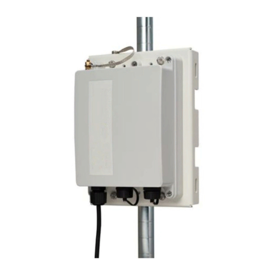
Page 2: Product Overview
The power injector’s AC power receptacle connects an approved AC power cord to a wall outlet or power strip. The power injector can be mounted on most horizontal and vertical surfaces, but must be mounted in a vertical orientation to comply with safety requirements. Cisco Aironet Series Power Injectors AIR-PWRINJ-60RGD1= and AIR-PWRINJ-60RGD2= Installation Instructions... -
Page 3: Air-Pwrinj-60Rgdx= Technical Specifications
EN61000-4-5 Class 5 (6kV CM) UL60950-1 & UL60950-22 Safety Approvals GS Mark Meets Surge Protection as specified in GR-1089-CORE Issue 4 Surge Protection ITU-T K.20 6 kV on AC lines Cisco Aironet Series Power Injectors AIR-PWRINJ-60RGD1= and AIR-PWRINJ-60RGD2= Installation Instructions... -
Page 4: Important Safety Information
You can determine whether your equipment is causing interference by turning it off. If the interference stops, it was probably caused by the Cisco equipment or one of its peripheral devices. If the equipment causes interference to radio or television reception, try to correct the interference by using one or more of the following measures: Turn the television or radio antenna until the interference stops. - Page 5 Safety Precautions Translated versions of the following safety warnings are provided in the Safety Warnings document that ships with the access point and is also available on Cisco.com. IMPORTANT SAFETY INSTRUCTIONS Warning This warning symbol means danger. You are in a situation that could cause bodily injury. Before you work on any equipment, be aware of the hazards involved with electrical circuitry and be familiar with standard practices for preventing accidents.
-
Page 6: Connectors On The Power Injector
Connectors on the Power Injector Figure 1 Earth Ground Connector on the Head of the Power Injector Figure 2 Power and Data Connectors on the Base of the Power Injector Cisco Aironet Series Power Injectors AIR-PWRINJ-60RGD1= and AIR-PWRINJ-60RGD2= Installation Instructions... -
Page 7: Unpacking The Power Injector
• Ground cable (Figure • If any item is missing or damaged, contact your Cisco representative or reseller. Warning To reduce the risk of fire, use only No. 26 AWG or larger telecommunication line cord. Statement 1023 Note You must use shielded outdoor rated Ethernet cables with this device. -
Page 8: Mounting The Power Injector On A Wall
1), and attach then other end to a permanent ground connection. The ground lug used is an M6 stud. Step 5 Proceed with the “Connecting Data and Power to the Injector” section on page Cisco Aironet Series Power Injectors AIR-PWRINJ-60RGD1= and AIR-PWRINJ-60RGD2= Installation Instructions... -
Page 9: Pole Mounting The Power Injector Using Air-Pwrinj-60-Pmk
Step 1 Fasten the bracket to the pole using the worm screw clamps and the M6*110 hexagon head screw, flat Step 2 washers, lock washers, and hexagon nuts. See Figure Cisco Aironet Series Power Injectors AIR-PWRINJ-60RGD1= and AIR-PWRINJ-60RGD2= Installation Instructions... - Page 10 1), and attach then other end to a permanent ground connection. Proceed with the “Connecting Data and Power to the Injector” section on page Step 5 Figure 5 Pole-Mounting the Power Injector Cisco Aironet Series Power Injectors AIR-PWRINJ-60RGD1= and AIR-PWRINJ-60RGD2= Installation Instructions...
-
Page 11: Connecting Data And Power To The Injector
Connect the other end of the power cord into a 100-VAC to 240-VAC power source Step 6 Table 1 AC Power Cord and Wire Sizes Type AC Cord Sizes Individual AC Wire Sizes RGD2= 6.8mm +/-0.4mm 0.75mm/3C RGD1= (for reference only) 8mm +/-0.4mm 18AWG/x3C Cisco Aironet Series Power Injectors AIR-PWRINJ-60RGD1= and AIR-PWRINJ-60RGD2= Installation Instructions... - Page 12 Connecting Data and Power to the Injector Figure 6 Assembling of Factory-Shipped Waterproof RJ45 Connectors Cisco Aironet Series Power Injectors AIR-PWRINJ-60RGD1= and AIR-PWRINJ-60RGD2= Installation Instructions...
-
Page 13: Power Injector Input And Output Connections
Ethernet signal pair (10/100/1000Base-T) and 55 VDC return Ethernet signal pair (10/100/1000Base-T) and 55 VDC (+) Ethernet signal pair (1000Base-T) and 55 VDC (+) Ethernet signal pair (1000Base-T) and 55 VDC return Shield Chassis ground Cisco Aironet Series Power Injectors AIR-PWRINJ-60RGD1= and AIR-PWRINJ-60RGD2= Installation Instructions... - Page 14 Power Injector Input and Output Connections Cisco Aironet Series Power Injectors AIR-PWRINJ-60RGD1= and AIR-PWRINJ-60RGD2= Installation Instructions...