Table of Contents

Related Manuals for Canon Staple Finisher-D1


Summary of Contents for Canon Staple Finisher-D1
- Page 1 May 5, 2010 Revision 0 Staple Finisher-D1 / Booklet Finisher-D1 Service Manual Product Outline Technology Periodic Servicing Parts Replacement and Cleaning Procedure F-0-1 F-0-1 Adjustment Installation Appendix...
- Page 2 This manual is copyrighted with all rights reserved. Under the copyright laws, this manual may changes in the contents of this manual over a long or short period, Canon will issue a new not be copied, reproduced or translated into another language, in whole or in part, without the written consent of Canon Inc.
- Page 3 relationship between electrical and mechanical systems with reference to the timing of Explanation of Symbols The following symbols are used throughout this Service Manual. operation. In the diagrams, represents the path of mechanical drive; where a signal name accompanies the symbol, the arrow indicates the direction of the electric Symbols Explanation...
-
Page 5: Table Of Contents
Outline -------------------------------------------------------------------------------- 2-5 Contents Basic Operations ------------------------------------------------------------------- 2-6 Straight Path Paper Feed Operation ------------------------------------------ 2-7 Processing Tray Paper Feed Operation -------------------------------------- 2-9 Buffer Path Paper Feed Operation -------------------------------------------2-10 Safety Precautions Switching Over the Paper Path ------------------------------------------------ 2-11 Stack Tray Unit -------------------------------------------------------------- 2-13 Notes Before it Works Servicing ------------------------------------------0-2 Stack Tray Operation ------------------------------------------------------------2-13 Product Outline... - Page 6 Removing the Grate-shaped Lower Guide ---------------------------------4-26 Periodic Servicing -----------------------------------------------------------------2-36 Upgrading ---------------------------------------------------------------------------2-36 Removing the Saddle Delivery Tray ------------------------------------------4-27 Removing the Stapler Drive Unit ----------------------------------------------4-28 Periodic Servicing Removing the Processing Tray Unit ------------------------------------------4-30 Pull out the Saddle Unit (Service Position) ---------------------------------4-32 List of Work for Scheduled Servicing ------------------------------------3-2 Removing the Saddle Unit ------------------------------------------------------4-34 Parts Replacement and Cleaning Procedure Removing the Thrust Unit -------------------------------------------------------4-37...
- Page 7 Overview ----------------------------------------------------------------------------- 5-2 Installing Options ------------------------------------------------------------------6-16 Preparation for Installation on Upstream Connection Machine Side Detail Description ------------------------------------------------------------------ 5-2 [Staple Finisher-D1 only] --------------------------------------------------------6-17 Major Adjustments ----------------------------------------------------------------- 5-2 Connecting to Host Machine ------------------------------------------------------------6-17 Basic Adjustment --------------------------------------------------------------5-3 Connecting to Document Insertion Unit ----------------------------------------------6-18...
- Page 8 [Booklet Finisher-D1 only] ------------------------------------------------------6-20 Connecting to Host Machine ------------------------------------------------------------6-20 Connecting to Document Insertion Unit ----------------------------------------------6-21 Connecting to Professional Puncher -------------------------------------------------6-21 Connecting to Paper Folding Unit -----------------------------------------------------6-22 Connecting to the Upstream Connection Machine -----------------------6-23 Making Adjustments -------------------------------------------------------- 6-30 Adjusting the Height and Tilt ---------------------------------------------------6-30 Checking the Difference in Height and the Tilt -------------------------------------6-30 Adjusting the Height and Tilt ------------------------------------------------------------6-32 Making Checks after Completion of Adjustments -------------------------6-36...
-
Page 9: Safety Precautions
Safety Precautions ■ Notes Before it Works Servicing... -
Page 10: Notes Before It Works Servicing
Safety Precautions > Notes Before it Works Servicing Notes Before it Works Servicing Caution: At servicing, be sure to turn off the power source according to the specified steps and disconnect the power plug. Caution: Do not turn off the power switch when downloading is under way. Turning off the main power switch while downloading is under way can disable the machine. -
Page 11: Product Outline
Product Outline ■ Features Specifications ■ ■ Names of Parts ■ Optional Construction Product Outline... - Page 12 Product Outline > Features Features The gripper function is installed in the processing tray unit , and it improves the stacking • alignment on the stack tray. The gripper operates at the sort and the staple sort mode. The four universal casters are installed, and it facilitates the maintenance work. •...
-
Page 13: Finisher Unit
Product Outline > Specifications > Finisher Unit Specifications Specifications Item Remarks [Tray 2: Non sort] Stacking capacity (without Z-folding - Plain paper Finisher Unit Small size: Height 195 mm -/+ 3 mm or less sheets) (equivalent of 1500 sheets) Large size: Height 97 mm -/+ 3 mm or less Specifications Item Remarks... -
Page 14: Staple Unit
Product Outline > Specifications > Staple Unit Staple Unit Specifications Item Remarks [Mode mixing] Combination of A4, B5, and LTR only: Height Specifications Item Remarks 195mm -/+ 3mm or less Stapling By rotating cam Flat clinch Combinations of other paper sizes: Height 97mm Small size*1 Large size*2 Stapling... -
Page 15: Saddle Stitcher Unit (Booklet Finisher-D1)
Product Outline > Specifications > Saddle Stitcher Unit (Booklet Finisher-D1) Saddle Stitcher Unit (Booklet Finisher-D1) • Staple Position Front 1-point stapling (30deg.) Rear 1-point stapling (30deg.) Specifications Item Remarks A3, B4, A4, A4R, B5, 8K, 16K, A3, B4, A4, A4R, B5, 8K, 16K, Vertically separated, round-clinch, stapling at two Stapling 11”... -
Page 16: Others
Folding method Roller contact - Booklet Finisher-D1 Folding mode Double folding About 106 kg Power supply 100-240V, 50/60Hz Folding positionPaper center Power consumption - Staple Finisher-D1 When the optional Folding position Provided Max. 178W machine is not installed. adjustment - Booklet Finisher-D1... -
Page 17: Names Of Parts
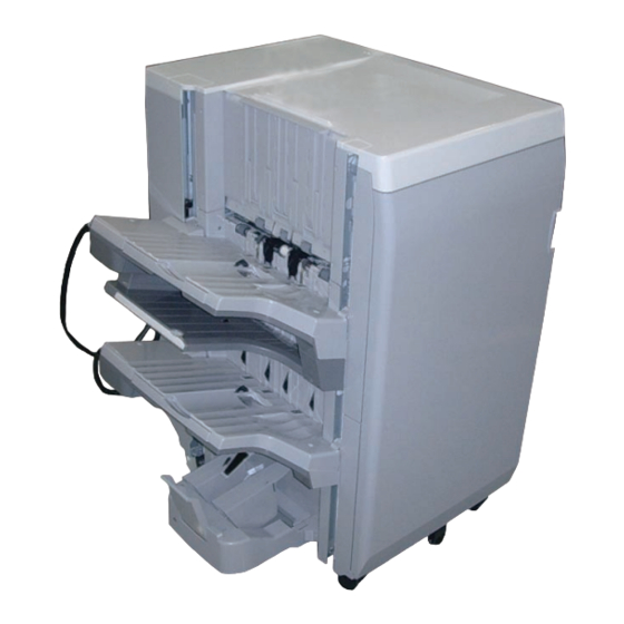
Product Outline > Names of Parts > External View(Front) > Saddle Finisher (Booklet Finisher) ■ Names of Parts Saddle Finisher (Booklet Finisher) Grate-shaped upper guide External View(Front) ■ Finisher (Staple Finisher) Tray 1 Grate-shaped upper guide Escape tray Front door Tray 1 Front door Escape tray... -
Page 18: External View(Rear)
Product Outline > Names of Parts > External View(Rear) > Saddle Finisher (Booklet Finisher) External View(Rear) ■ Saddle Finisher (Booklet Finisher) ■ Rear upper cover Finisher (Staple Finisher) Rear upper cover Rear lower cover Rear lower cover F-1-6 F-1-6 F-1-5 F-1-5 Product Outline >... -
Page 19: Saddle Finisher (Booklet Finisher)
Product Outline > Names of Parts > External View(Internal) > Saddle Finisher (Booklet Finisher) External View(Internal) ■ Saddle Finisher (Booklet Finisher) Saddle stitcher F-1-7 F-1-7 Product Outline > Names of Parts > External View(Internal) > Saddle Finisher (Booklet Finisher) -
Page 20: Cross Section(Front)
Product Outline > Names of Parts > Cross Section(Front) > Finisher (Staple Finisher) 1-10 Cross Section(Front) Tray 2 Feed roller 3 ■ Finisher (Staple Finisher) Escape tray Disengage roller Buffer flapper Tray 1 [10] [10] Saddle inlet flapper [11] Stapler unit [11] Lower stack delivery roller [12]... - Page 21 Product Outline > Names of Parts > Cross Section(Front) > Saddle Finisher (Booklet Finisher) 1-11 ■ Saddle Finisher (Booklet Finisher) Saddle inlet roller [13] Stapler unit [16] [17] [18] [19] [21] [15] [20] Lower stack delivery roller Saddle inlet delivery roller [14] Upper stack delivery roller Stitcher unit...
-
Page 22: Saddle Finisher (Booklet Finisher)
Product Outline > Optional Construction 1-12 - Saddle Finisher (Booklet Finisher) Optional Construction The following two optional machines can install to the finisher. Inner Puncher Unit • Punch Unit-BE1: AB, 2 holes Punch Unit-BF1: Inch, 2/3 holes Punch Unit-BG1 FRN, 2/4 holes Punch Unit-BH1: SWE, 4 holes Inner Trimmer Unit •... -
Page 23: Technology
Technology ■ Basic Configuration ■ Controls ■ Feeding Unit ■ Stack Tray Unit ■ Processing Tray Unit Saddle Stitcher Unit ■ ■ Controller Unit ■ Detecting Jams Power Supply ■ ■ Work of Service Technology... -
Page 24: Functional Configuration
Technology > Basic Configuration > Functional Configuration Basic Configuration - Saddle Finisher (Booklet Finisher) 2.Processing tray unit 1.Feeding unit Functional Configuration The components of this saddle finisher are organized into 4 major blocks and this finisher are organized into 3 major blocks; feed unit, processing unit, stack tray unit and saddle stitcher 3.Stacking tray unit unit. -
Page 25: Overview Of Electrical Circuitry
Technology > Basic Configuration > Overview of Electrical Circuitry Overview of Electrical Circuitry -Saddle Finisher (Booklet Finisher) Motor The machine’s sequence of the operations is controlled by its finisher controller PCB. Finisher Host Machine controller PCB The finisher controller PCB has the 16-bit CPU, and the controller also controls the communication with the host machine, the saddle stitcher controller PCB and the punch unit Clutch (option) in addition to controlling the machine’s operation sequence. -
Page 26: Controls
Technology > Controls > Controls Controls Controls Item Reference 1. Feeding Unit Outline Refer to page 2-5 Basic Operations Refer to page 2-6 Straight Path Paper Feed Operation Refer to page 2-7 Processing Tray Paper Feed Refer to page 2-9 Operation Buffer Path Paper Feed Operation Refer to page 2-10... -
Page 27: Feeding Unit
Technology > Feeding Unit > Outline Feeding Unit Finisher Controller PCB [10] [11] [12] [13] Outline The feeding unit feeds the paper to the stacking tray or the saddle stitcher unit in response to M116 M117 M114 M110 M108 M109 M113 M112 M118... -
Page 28: Basic Operations
Technology > Feeding Unit > Basic Operations Basic Operations Finisher Controller PCB The feeding unit uses the following 4 sequences of operation: [1] Straight Path Paper Feed Operation The feeding unit delivers the paper that fed from the upstream connection machine on the stacking tray without stacking the paper to the processing tray unit. -
Page 29: Straight Path Paper Feed Operation
Technology > Feeding Unit > Straight Path Paper Feed Operation At this time, if the paper length is under 257mm, the feed roller disengage/buffer flapper Straight Path Paper Feed Operation motor (M119) drives so that the disengage roller and the feed roller 3 contact. When the shift or staple mode is not selected, this finisher delivers the paper on the stacking tray unit immediately without stacking the paper to the processing tray unit. - Page 30 Technology > Feeding Unit > Straight Path Paper Feed Operation When the feed path senor (S102) has detected the paper, the stacking tray paper retainer After delivering the paper, the stacking tray raises or lowers according to the position of the holds the paper on the stacking tray.
-
Page 31: Processing Tray Paper Feed Operation
Technology > Feeding Unit > Processing Tray Paper Feed Operation The light-emitting (PBA600) and the light-receiving (PBA700) of the tray paper surface sensor Processing Tray Paper Feed Operation detect the surface of the stack of paper on the stacking tray. When the shift or staple mode is selected, this finisher stacks the paper on the processing When the tray paper surface sensor has detected the paper, the stacking tray lowers by 2mm. -
Page 32: Buffer Path Paper Feed Operation
Technology > Feeding Unit > Buffer Path Paper Feed Operation 2-10 The feed roller disengage/buffer flapper motor (M119) drives and the buffer flapper switches Buffer Path Paper Feed Operation over. The paper that fed from the upstream connection machine stacks to the buffer path unit while Then, the buffer feed motor (M102) drives in the opposite direction and the feeding unit feeds the shift or staple operation performs in the processing tray unit. -
Page 33: Switching Over The Paper Path
Technology > Feeding Unit > Switching Over the Paper Path 2-11 Switching Over the Paper Path The feed roller disengage/buffer flapper motor (M119) drives to switches over the buffer flapper. The saddle inlet flapper solenoid (SL206) drives to switches over the saddle inlet flapper. As Then, the buffer feed motor (M102) drives and the feeding unit feeds a sheet of paper that a result, the sheet of paper that fed from the upstream connection machine feeds toward the stacked in the buffer path together with a subsequent sheet of paper. - Page 34 Technology > Feeding Unit > Switching Over the Paper Path 2-12 MEMO: Stack Delivery Auxiliary Function This finisher is equipped with the stack delivery auxiliary mechanism as a means of preventing misalignment of extra-length paper.Misalignment occurs when the trail edge of paper hangs down on its own weight at the stack delivery operation.
-
Page 35: Stack Tray Unit
Technology > Stack Tray Unit > Stack Tray Operation 2-13 Stack Tray Unit Rack Stack Tray Operation This equipment has three delivery trays. The upper tray is called escape tray, the middle tray is called tray 1, and the lower tray is called tray2. The escape tray is fixed and tray 1 and tray Tray 1 Paper Sensor 2 can move up and down independently. -
Page 36: Shutter Operation
Technology > Stack Tray Unit > Shutter Operation 2-14 Tray 1 Paper Sensor Shutter Operation Sensor Tray 1 When tray 1 passes the delivery section with paper already stacked, the stacked paper may get caught by the delivery section. A shutter is provided at the delivery section to prevent this. The shutter closes when tray 1 passes the delivery section. -
Page 37: Processing Tray Unit
Technology > Processing Tray Unit > Outline 2-15 Processing Tray Unit [8] Alignment Plate (rear) [9] Gripper [10] Stopper [10] Stopper Outline [9] Gripper In the processing tray unit, the fed sheets are stacked to be shifted or stapled. The stack of [10] Stopper sheets is then delivered to the stacking tray. -
Page 38: Basic Operation
Technology > Processing Tray Unit > Basic Operation 2-16 Basic Operation Name Function The processing tray unit performs four types of basic operations described below. Presses down the sheets stacked in the processing tray Paper Retainer unit to prevent them from being delivered or fed. Holds down and feeds paper to the processing stopper Paper Return Guide 1.Processing Tray Paper Stacking Operation... -
Page 39: Processing Tray Paper Stacking Operation
Technology > Processing Tray Unit > Processing Tray Paper Stacking Operation 2-17 3) When the trailing edge of paper passes by the front delivery roller, the paper trailing edge Processing Tray Paper Stacking Operation pushing guide motor (M113) is driven to lower the paper trailing edge pushing guide, thus 1) When the paper fed from the feed unit reaches the feed path paper sensor (S108), the pushing down the paper in the stacking direction of the processing tray. -
Page 40: Shift Operation
Technology > Processing Tray Unit > Shift Operation 2-18 5) The front/rear alignment motor (M108/M109) is driven to move the alignment plate (front/ Shift Operation rear), thus aligning the sheets stacked in the processing tray. This operation is performed Sheets fed to the processing tray are aligned to the front or rear using the alignment plates. each time paper is fed to the processing tray. -
Page 41: Staple Operation
Technology > Processing Tray Unit > Staple Operation 2-19 Stapling and alignment positions in different staple modes are as follows: Staple Operation <Front 1-Point Stapling> Sheets are stapled after being fed to the processing tray and aligned there. Alignment position: Sheets are aligned to the center when the paper width is more than 216 mm. - Page 42 Technology > Processing Tray Unit > Staple Operation 2-20 <Rear 1-Point Stapling> <2-Point Stapling> Alignment position: Sheets are aligned to the center when the paper width is more than 216 Sheets are stapled at the rear, and then stapled at the front. mm.
-
Page 43: Stack Delivery Operation
Technology > Processing Tray Unit > Swing Height Detection Control 2-21 Swing Height Detection Control Stack Delivery Operation The height of the sheets stacked in the processing tray is detected by the swing height Trailing edges of the sheets stacked in the processing tray unit are gripped by driving the gripper base motor (M116) and gripper motor (M117), and the paper stack is delivered to the detection sensor (S118) and the height of the swing unit is adjusted appropriately (during stacking of a sheet in the processing tray) to lessen the damages (scratches, etc.) to the... -
Page 44: Saddle Stitcher Unit
Technology > Saddle Stitcher Unit > Outline 2-22 Saddle Stitcher Unit Saddle guide motor drive signal M201 Saddle transport motor Alignment roller disengage solenoid M202 Saddle alignment guide motor Outline (lower) drive signal Saddle alignment roller drive signal M203 Saddle lead edge stopper motor The saddle stitcher block serves to staple a stack of sheets according to the instructions from Alignment roller disengage solenoid M204... -
Page 45: Basic Sequence Of Operations
Technology > Saddle Stitcher Unit > Basic Sequence of Operations 2-23 Basic Sequence of Operations Saddle stitcher controller PCB The saddle stitcher block uses the following sequence of operations: Transport Moves the paper from the transport block to the vertical path assembly. Alignment Aligns the edges of sheets of paper coming to the transport block. -
Page 46: Paper Feed Operation
Technology > Saddle Stitcher Unit > Paper Feed Operation 2-24 The paper is transported to the stitcher unit by the saddle feed roller. Paper Feed Operation Once the saddle inlet sensor (PS201) detects the paper, the saddle alignment roller The saddle leading edge stopper and saddle trailing edge stay move into position based rotates and drives the saddle pull roller disengage motor and the saddle alignment roller on the paper size. -
Page 47: Roller Guide Clearance Control
Technology > Saddle Stitcher Unit > Roller Guide Clearance Control 2-25 The clearance between the roller guide and the saddle process tray changes in accordance Roller Guide Clearance Control with the position of shutter shift block (hereinafter called as shift block). In case of thin paper if the clearance between the roller guide and the saddle process tray is The Saddle Roller Guide Motor (M204) lifts the shift block. -
Page 48: Alignment Operation
Technology > Saddle Stitcher Unit > Alignment Operation 2-26 Alignment Operation The machine engages the alignment roller again and the paper is pushed to the leading The machine opens the trailing edge retainer and disengages the alignment roller and edge stopper, and then the knocking plate taps the trailing edge of paper. lead-in roller. -
Page 49: Staple Operation
Technology > Saddle Stitcher Unit > Staple Operation 2-27 Staple Operation There is one sticker unit at the front and the rear of the machine respectively. When the The machine disengages the alignment roller and the trailing edge retainer holds the alignment operation is complete and the trailing edge retainer is released, the stitcher trailing edge of paper. -
Page 50: Paper Folding/Delivery Operations
Technology > Saddle Stitcher Unit > Paper Folding/Delivery Operations 2-28 With the sheaf held in place by the gripper the paper positioning plate lowers, moving Paper Folding/Delivery Operations the sheaf in the direction of the arrow. Thus, the stitching position and the folding The saddle roller guide is lowered and then the Saddle Lead Edge Stopper Solenoid position are aligned. - Page 51 Technology > Saddle Stitcher Unit > Paper Folding/Delivery Operations 2-29 After the paper folding roller begins to rotate in the direction of the arrow, the paper guide plate moves in the direction of the arrow. This starts the paper folding operation. Then, the paper guide plate is returned to its original position and stops.
-
Page 52: Controller Unit
Technology > Controller Unit > Finisher Controller PCB 2-30 Controller Unit Finisher Controller PCB The finisher controller PCB drives the various loads (motors, solenoids) of the machine in Outline response to the commands from the host machine (copier), and indicates the states of the sensors and switches to the host machine. -
Page 53: Saddle Stitcher Controller Pcb
Technology > Controller Unit > Saddle Stitcher Controller PCB 2-31 The machine uses the following ICs, each possessing specific functions: Saddle Stitcher Controller PCB Name Description The saddle stitcher controller PCB drives the machine's various loads (motors, solenoids) in CPU(IC1) Controls the communications with the host machine. -
Page 54: Detecting Jams
Technology > Detecting Jams > Detecting Jams 2-32 - Finisher (Staple Finisher) Detecting Jams Detecting Jams To detect whether there is paper or not, or whether the paper can properly be fed or not, the followings are the detection sensor for paper •... - Page 55 Technology > Detecting Jams > Detecting Jams 2-33 Whether jam is occurred or not, determined by whether there is paper or not in the sensor - Saddle Finisher (Booklet Finisher) area by the time of timing check that memorized in advance by Finisher Controller PCB and Saddle Stitcher Controller PCB.
-
Page 56: Power Supply
Technology > Power Supply > Protective Functions 2-34 Power Supply Outline This machine incorporates the power supply PCB to supply DC power to every PCB. The following table summarizes functions of DC power supply units. Name Function Power supply PCB Generates DC power (24V) and supplies DC power to the finisher controller PCB and saddle stitcher controller PCB. - Page 57 Technology > Power Supply > Protective Functions 2-35 - Finisher (Staple Finisher) Finisher Controller PCB Relay signal (+24V) Filter PCB Power +3.3V logic system Supply +5V logic system SW101 Sensors SW102 SW104 Motor SW110 SW111 SW103 Clutch Solenoid Motor F-2-56 F-2-56 SW101: Front door switch SW102: Swing guide safety switch (front)
-
Page 58: Work Of Service
Technology > Work of Service > Upgrading 2-36 Work of Service Periodic Servicing When the parts are reaching the expected service life, perform the parts replacement or When replacing the parts cleaning if needed. PR:Replacement (Periodically replaced parts) CR:Replacement (consumable parts) CL: When replacing the following parts, perform the operations. -
Page 59: Periodic Servicing
Periodic Servicing ■ List of Work for Scheduled Servicing Periodic Servicing... - Page 60 Periodic Servicing > List of Work for Scheduled Servicing List of Work for Scheduled Servicing PR:Replacement (Periodically replaced parts) CR:Replacement (consumable parts) CL:Cleaning LU:Lubrication AD:Adjustment CH:Maintenance As of July 2009 Q'ty Category Part Name Part Number Interval Adjusted/Not Counter Reference adjusted CR/1,000,000 sheets DRBL-2>DL-STC-R...
-
Page 61: Parts Replacement And Cleaning Procedure
■ Other Parts Parts ■ Switches Replacement ■ PCBs and Cleaning Procedure List of Parts ■ ■ External / Internal Covers ■ Main Units ■ Consumable Parts Requiring Periodic Replacement and Cleaning Points ■ Clutchs/Solenoids ■ Motors Parts Replacement and Cleaning Procedure... -
Page 62: External / Internal Covers
Parts Replacement and Cleaning Procedure > List of Parts > External / Internal Covers List of Parts Name Part No Refer to Front Door FC9-3441 Refer to page 4-17 External / Internal Covers Upper Cover FC9-3449 Refer to page 4-18 Rear Cover (Upper) FC9-3445 Refer to page 4-19... - Page 63 Parts Replacement and Cleaning Procedure > List of Parts > External / Internal Covers - Saddle Finisher (Booklet Finisher) Name Part No Refer to Front Door FC9-2692 Refer to page 4-17 Upper Cover FC9-2699 Refer to page 4-18 Rear Cover (Upper) FC9-2695 Refer to page 4-19 Rear Cover (Lower)
-
Page 64: Main Units
Parts Replacement and Cleaning Procedure > List of Parts > Consumable Parts Requiring Periodic Replacementand Cleaning Points Main Units Consumable Parts Requiring Periodic Replacementand Cleaning Points Name Part No Refer to Grate-shaped Upper Guide Refer to page 4-23 Name Part No Refer to Tray-1 Unit/Tray-2 Unit Refer to page 4-24... -
Page 65: List Of Solenoid
Parts Replacement and Cleaning Procedure > List of Parts > List of Solenoid List of Solenoid SL101 SL206 SL203 SL204 SL205 F-4-6 F-4-6 Name Part No Refer to F-4-5 F-4-5 SL203 Saddle Alignment Roller Disengage Solenoid FK2-1782 Name Part No Refer to (Upper) SL101... -
Page 66: List Of Clutchs
Parts Replacement and Cleaning Procedure > List of Parts > List of Cooling Fans List of Clutchs List of Cooling Fans CL102 FAN101 F-4-7 F-4-7 F-4-8 F-4-8 Name Part No Refer to Name Part No Refer to CL102 Power Supply Fan Shutter Clutch FK2-8207 Refer to page 4-54... -
Page 67: List Of Motors
Parts Replacement and Cleaning Procedure > List of Parts > List of Motors List of Motors Name Part No Refer to M101 Feed Motor FK2-8199 Refer to page 4-68 M102 Buffer Feed Motor FK2-8199 Refer to page 4-67 Stack Delivery Upper Motor M104 FK2-8199 Refer to page 4-69... - Page 68 Parts Replacement and Cleaning Procedure > List of Parts > List of Motors Name Part No Refer to M105 Tray 1 Shift Motor FK2-8200 Refer to page 4-63 M106 Tray 2 Shift Motor FK2-8200 Refer to page 4-64 M107 Stapler Shift Motor FK2-8200 Refer to page 4-65 M115...
- Page 69 Parts Replacement and Cleaning Procedure > List of Parts > List of Motors - Finisher (Staple Finisher) - Saddle Finisher (Booklet Finisher) M200 M200 M213 M201 M211 M214 M210 M204 M203 M202 M212 M206 M205 F-4-11 F-4-11 F-4-12 F-4-12 Parts Replacement and Cleaning Procedure > List of Parts > List of Motors...
- Page 70 Parts Replacement and Cleaning Procedure > List of Parts > List of Motors 4-10 Name Part No Refer to M200 Inlet Feed Motor FK2-8199 Refer to page 4-66 M201 Saddle Feed Motor FK2-8184 M202 Saddle Alignment Guide Motor FK2-1730 Saddle Lead Edge Stopper Motor M203 FK2-1732 M204...
-
Page 71: List Of Sensors
Parts Replacement and Cleaning Procedure > List of Parts > List of Sensors 4-11 List of Sensors Name Part No Refer to S102 Feed Path Sensor WG8-5854 S103 Processing Tray Paper Sensor FK2-1772 S106 Shutter HP Sensor WG8-5823 S107 Stapler Shift HP Sensor WG8-5823 S108 Front Alignment HP Sensor... - Page 72 Parts Replacement and Cleaning Procedure > List of Parts > List of Sensors 4-12 Name Part No Refer to S104 Tray 1 Paper Sensor WG8-5823 S105 Tray 2 Paper Sensor WG8-5823 S122 Tray 1 Area Sensor 1 FM4-2175 S123 Tray 1 Area Sensor 2 S124 Tray 1 Area Sensor 3 S125...
- Page 73 Parts Replacement and Cleaning Procedure > List of Parts > List of Sensors 4-13 Name Part No Refer to S201 Saddle Inlet Sensor WG8-5854 S203 Saddle Vertical Path Sensor FK2-1772 Saddle Lead Edge Stopper HP Sensor S205 WG8-5823 S206 Saddle Alignment Plate HP Sensor WG8-5823 S207 Saddle Roller Guide HP Sensor...
-
Page 74: List Of Switchs
Parts Replacement and Cleaning Procedure > List of Parts > List of Switchs 4-14 List of Switchs Name Part No Refer to BK101 Breaker FH7-7625 Front Door Switch SW101 WC4-5301 Staple Safety Switch (Front) SW102 WC4-5301 Refer to page 4-79 Swing Guide Switch SW103 WC4-5301... -
Page 75: List Of Pcbs
Parts Replacement and Cleaning Procedure > List of Parts > List of PCBs 4-15 List of PCBs Name Part No Refer to PBA101 Finisher Controller PCB FM4-2173 Refer to page 4-80 PBA300 Tray 1 Motor Driver PCB FM4-2174 Refer to page 4-81 PBA301 Tray 2 Motor Driver PCB... -
Page 76: Other
Parts Replacement and Cleaning Procedure > List of Parts > Other 4-16 Other Name Part No Refer to Alignment Roller FC8-7495 Refer to page 4-71 Thrust Plate FM4-3083 Refer to page 4-74 Folding Rollers (Upper)/(Lower) FC9-2580 Refer to page 4-75 T-4-18 T-4-18 PBA250... -
Page 77: External / Internal Covers
Parts Replacement and Cleaning Procedure > External / Internal Covers > Removing the Front Door (Saddle Finisher [Booklet Finisher]) 4-17 External / Internal Covers Removing the Front Door (Finisher [Staple Finisher]) 1) Open the front door. 2) Remove the clip and detach the front door. F-4-19 F-4-19 F-4-20... -
Page 78: Removing The Upper Cover (Finisher [Staple Finisher])
Parts Replacement and Cleaning Procedure > External / Internal Covers > Removing the Upper Cover (Saddle Finisher [Booklet Finisher]) 4-18 Removing the Upper Cover (Finisher [Staple Finisher]) 2) Remove the 2 screws detach the upper cover. 1) Open the front door. F-4-23 F-4-23 F-4-24... -
Page 79: Removing The Rear Cover (Upper)
Parts Replacement and Cleaning Procedure > External / Internal Covers > Removing the Rear Cover (Lower) 4-19 Removing the Rear Cover (Upper) 1) Release the hook with the flat head screwdriver, and then remove the PCB cover. 2) Remove the 4 screws and detach the rear cover (upper). F-4-27 F-4-27 F-4-28... -
Page 80: Removing The Left Inner Cover (Finisher [Staple Finisher])
Parts Replacement and Cleaning Procedure > External / Internal Covers > Removing the Left Inner Cover (Saddle Finisher [Booklet Finisher]) 4-20 Removing the Left Inner Cover (Finisher [Staple Finisher]) 2) Remove the 4 screws and detach the left inner cover. 1) Open the front door. -
Page 81: Removing The Right Inner Cover (Finisher [Staple Finisher])
Parts Replacement and Cleaning Procedure > External / Internal Covers > Removing the Right Inner Cover (Saddle Finisher [Booklet Finisher]) 4-21 Removing the Right Inner Cover (Finisher [Staple Finisher]) 2) Remove the 2 screws and detach the right inner cover. 1) Open the front door. -
Page 82: Removing The Saddle Stitcher Cover
Parts Replacement and Cleaning Procedure > External / Internal Covers > Removing the Saddle Stitcher Cover 4-22 Removing the Saddle Stitcher Cover 3) Remove three screws, and then remove the inner 1) Open the front door. 2) Remove the jam dial (upper). Remove one screw, and then remove the jam dial (lower). -
Page 83: Main Units
Parts Replacement and Cleaning Procedure > Main Units > Removing the Grate-shaped Upper Guide 4-23 Main Units Removing the Grate-shaped Upper Guide 1) Remove the 8 screws while lifting the paper holding guide, and then remove the grate-shaped upper guide. F-4-42 F-4-42 CAUTION:... -
Page 84: Removing The Tray-1 Unit / Tray-2 Unit
Parts Replacement and Cleaning Procedure > Main Units > Removing the Tray-1 unit / Tray-2 unit 4-24 Removing the Tray-1 unit / Tray-2 unit 1) Remove the finger-pinch prevention covers (front) and (rear). F-4-45 F-4-45 2) Remove the 2 screws and then remove the tray stoppers (front) and (left). F-4-46 F-4-46 4-24... - Page 85 Parts Replacement and Cleaning Procedure > Main Units > Removing the Tray-1 unit / Tray-2 unit 4-25 3) Lift the paper holding guide to remove it from the grate-shaped 4) Remove the tray-2 unit. upper guide and then remove the tray-1 unit. F-4-48 F-4-48 F-4-47...
-
Page 86: Removing The Grate-Shaped Lower Guide
Parts Replacement and Cleaning Procedure > Main Units > Removing the Grate-shaped Lower Guide 4-26 Removing the Grate-shaped Lower Guide 2) After lifting the tray-2 unit to the maximum point, remove the 9 screws to 1) Remove the tray-1 detach the grate-shaped lower guide. unit. -
Page 87: Removing The Saddle Delivery Tray
Parts Replacement and Cleaning Procedure > Main Units > Removing the Saddle Delivery Tray 4-27 Removing the Saddle Delivery Tray 1) Lift the tray-1 unit and the tray-2 unit until they will stop. F-4-51 F-4-51 2) Press the hooks to release them and detach the saddle delivery tray, and then disconnect the connector. F-4-52 F-4-52 F-4-53... -
Page 88: Removing The Stapler Drive Unit
Parts Replacement and Cleaning Procedure > Main Units > Removing the Stapler Drive Unit 4-28 Removing the Stapler Drive Unit 3) Release the harness for the stapler drive unit from the 3 wire saddles, and then remove 2 connectors (10P and 2P). 1) Remove the stapler unit. - Page 89 Parts Replacement and Cleaning Procedure > Main Units > Removing the Stapler Drive Unit 4-29 6) Remove the 2 screws and draw out the stapler drive unit. F-4-57 F-4-57 4-29 Parts Replacement and Cleaning Procedure > Main Units > Removing the Stapler Drive Unit...
-
Page 90: Removing The Processing Tray Unit
Parts Replacement and Cleaning Procedure > Main Units > Removing the Processing Tray Unit 4-30 Removing the Processing Tray Unit 2) Draw out the saddle stitcher unit. 1) Remove the stapler drive unit. (Refer to page 4-28) F-4-58 F-4-58 4) Remove the 3 screws and take out the bottom plate. 3) Disconnect the 5 connectors. - Page 91 Parts Replacement and Cleaning Procedure > Main Units > Removing the Processing Tray Unit 4-31 5) Remove the E-ring at the rear side and shift the bearing to the 6) Shift the drive shaft to the rear to release it from the front belt. 7) Shift the drive shaft to the front to release it from the rear belt, and then remove the drive shaft.
-
Page 92: Pull Out The Saddle Unit (Service Position)
Parts Replacement and Cleaning Procedure > Main Units > Pull out the Saddle Unit (Service Position) 4-32 Pull out the Saddle Unit (Service Position) 2) Pull out the saddle unit until it will stop. 1) Remove the front door. (Refer to page 4-17) F-4-67 F-4-67 3) Release the rail stopper and pull out the saddle unit further about 5 cm. - Page 93 Parts Replacement and Cleaning Procedure > Main Units > Pull out the Saddle Unit (Service Position) 4-33 CAUTION: Draw it out slowly. If it is drown out too much, the • saddle cable and the cable guide may be damaged. When the saddle unit is return into the finisher from •...
-
Page 94: Removing The Saddle Unit
Parts Replacement and Cleaning Procedure > Main Units > Removing the Saddle Unit 4-34 Removing the Saddle Unit 1) Pull out the saddle unit to the service position. (Refer to page 4-32) 2) Disconnect the connector and release the harness from the wire saddle on the rear of the saddle unit. F-4-70 F-4-70 F-4-71... - Page 95 Parts Replacement and Cleaning Procedure > Main Units > Removing the Saddle Unit 4-35 3) Remove the screw and disconnect the 3 connectors, and then remove the cable guide. F-4-72 F-4-72 4) Move the saddle unit to the position where the screw can be seen from the hole, and remove the screws. F-4-73 F-4-73 4-35...
- Page 96 Parts Replacement and Cleaning Procedure > Main Units > Removing the Saddle Unit 4-36 5) Remove the 2 screws from the rail (left) and rail (right). 6) Hold the saddle unit as shown in the figure, lift it as the direction of the arrow, make sure that it has parted from the rail, and carry it.
-
Page 97: Removing The Thrust Unit
Parts Replacement and Cleaning Procedure > Main Units > Removing the Thrust Unit 4-37 Removing the Thrust Unit 3) Remove the 6 screws and then remove the PCB cover. 1) Remove the saddle cover. (Refer to page 4-22) 2) Pull out the saddle unit to the service position. - Page 98 Parts Replacement and Cleaning Procedure > Main Units > Removing the Thrust Unit 4-38 6) Release the harness from the wire saddle and disconnect the 7) Remove the 4 screws and then remove the thrust unit. connector. F-4-81 F-4-81 F-4-80 F-4-80 4-38 Parts Replacement and Cleaning Procedure >...
-
Page 99: Consumable Parts Requiring Periodic Replacement And Cleaning Points
Parts Replacement and Cleaning Procedure > Consumable Parts Requiring Periodic Replacement and Cleaning Points > Removing the Static Eliminator (Feed Guide Unit) 4-39 Consumable Parts Requiring Periodic Replacement and Cleaning Points Removing the Static Eliminator (Feed Guide Unit) 2) Remove the screw and then remove the static eliminator. 1) Open the front door. -
Page 100: Removing The Shutter Torque Limiter
Parts Replacement and Cleaning Procedure > Consumable Parts Requiring Periodic Replacement and Cleaning Points > Removing the Stapler Unit 4-40 Removing the Shutter Torque Limiter 1) Open the front door. 2) Remove the left inner 3) Pull out the pin and remove the shutter torque limiter. cover. -
Page 101: Removing The Paper Holding Torque Limiter
Parts Replacement and Cleaning Procedure > Consumable Parts Requiring Periodic Replacement and Cleaning Points > Removing the Paper Holding Torque Limiter 4-41 4) Disconnect the connector and remove the 2 screws, and then remove the stapler unit. F-4-89 Removing the Paper Holding Torque Limiter 2) Remove the 2 screws and open the finisher controller 1) Remove the rear cover 3) Pull out the pin and remove the paper holding torque limiter. -
Page 102: Removing The Tray-1 Torque Limiter
Parts Replacement and Cleaning Procedure > Consumable Parts Requiring Periodic Replacement and Cleaning Points > Removing the Tray-1 Torque Limiter 4-42 Removing the Tray-1 Torque Limiter 1) Remove the 7 screws and remove the tray-1 upper cover. 2) Remove the screw and take out the torque limiter unit. F-4-94 F-4-92 F-4-93... -
Page 103: Removing The Tray-2 Torque Limiter
Parts Replacement and Cleaning Procedure > Consumable Parts Requiring Periodic Replacement and Cleaning Points > Removing the Tray-2 Torque Limiter 4-43 Removing the Tray-2 Torque Limiter 1) Remove the 7 screws and remove the tray-2 upper cover. 2) Remove the screw and take out the torque limiter unit. F-4-98 F-4-96 F-4-97... -
Page 104: Removing The Static Eliminators (Swing Guide Unit)
Parts Replacement and Cleaning Procedure > Consumable Parts Requiring Periodic Replacement and Cleaning Points > Removing the Static Eliminators (Swing Guide Unit) 4-44 Removing the Static Eliminators (Swing Guide Unit) 2) Lower the swing guide. 3)Remove the 6 screws and then remove the swing guide upper 1) Remove the grate- shaped upper guide. -
Page 105: Checking The Position Attached The Swing Guide Unit
Parts Replacement and Cleaning Procedure > Consumable Parts Requiring Periodic Replacement and Cleaning Points > Checking the position attached the Swing Guide Unit 4-45 Checking the position attached the Swing Guide Unit 1) Raise the swing guide unit while pushing the plunger of the swing guide solenoid, and 2) Loosen two screws and shift the position of the swing guide open then check that the gap between the swing guide upper cover and the arm of the staple solenoid to adjust the position of the staple safety switch's arm. -
Page 106: Removing The Stack Delivery Upper Roller
Parts Replacement and Cleaning Procedure > Consumable Parts Requiring Periodic Replacement and Cleaning Points > Removing the Stack Delivery Upper Roller 4-46 Removing the Stack Delivery Upper Roller 1) Remove the static 2) Remove the paper guide. eliminators (swing guide unit). (Refer to page 4-39) F-4-106 3) Release the bushings from the hooks. -
Page 107: Removing The Sub Guide Torque Limiter
Parts Replacement and Cleaning Procedure > Consumable Parts Requiring Periodic Replacement and Cleaning Points > Removing the Sub Guide Torque Limiter 4-47 Removing the Sub Guide Torque Limiter 1) Remove the grate- 2) Remove the 2 clips and shift the 2 bushings to the outside. shaped lower guide. -
Page 108: Removing The Static Eliminator (Grate-Shaped Lower Guide Unit)
Parts Replacement and Cleaning Procedure > Consumable Parts Requiring Periodic Replacement and Cleaning Points > Removing the Paper Holding Rubber 4-48 Removing the Static Eliminator (Grate-shaped lower guide unit) 1) Lift the tray 1 unit until it will stop. Remove the screw and take out the static eliminator. F-4-113 Removing the Paper Holding Rubber 1) Lift the tray 1 unit until it will stop. -
Page 109: Removing The Swing Guide Open Solenoid (Sl101)
Parts Replacement and Cleaning Procedure > Consumable Parts Requiring Periodic Replacement and Cleaning Points > Removing the Swing Guide Open Solenoid (SL101) 4-49 Removing the Swing Guide Open Solenoid (SL101) 2) Lower the swing guide and put a mark on the fixed position of the swing open solenoid. 3) Release the solenoid harness from the edge saddle, and then remove 1) Remove the grated- the 2 screws to remove the swing open solenoid. -
Page 110: Removing The Torque Limiter (Tray1/2 Paper Holder)
Parts Replacement and Cleaning Procedure > Consumable Parts Requiring Periodic Replacement and Cleaning Points > Removing the Torque Limiter (Tray1/2 Paper Holder) 4-50 Removing the Torque Limiter (Tray1/2 Paper Holder) 3) Remove the 2 screws and then remove the paper holder shaft plates 1) Remove the grated- 2) Take off the 3 belts from the pulleys. -
Page 111: Remove The Paper Holding Rollers (Front) And (Left)
Parts Replacement and Cleaning Procedure > Consumable Parts Requiring Periodic Replacement and Cleaning Points > Remove the Paper Holding Rollers (Front) and (Left) 4-51 CAUTION: After installing the 2 torque limiters (tray1/2 paper holder), turn the drive shaft to the allow direction to put away the tray paper holder lever in the processing tray unit. - Page 112 Parts Replacement and Cleaning Procedure > Consumable Parts Requiring Periodic Replacement and Cleaning Points > Remove the Paper Holding Rollers (Front) and (Left) 4-52 3) Slide the bushing to the outside and then remove the paper return guide roller units (front) and (rear). F-4-122 CAUTION: When installing the paper...
- Page 113 Parts Replacement and Cleaning Procedure > Consumable Parts Requiring Periodic Replacement and Cleaning Points > Remove the Paper Holding Rollers (Front) and (Left) 4-53 CAUTION: Fit the roller shaft into the opening of the drive shaft arm. F-4-123 4-53 Parts Replacement and Cleaning Procedure > Consumable Parts Requiring Periodic Replacement and Cleaning Points > Remove the Paper Holding Rollers (Front) and (Left)
-
Page 114: Removing The Paper Holding Roller
Parts Replacement and Cleaning Procedure > Consumable Parts Requiring Periodic Replacement and Cleaning Points > Removing the Shutter Clutch (CL102) 4-54 Removing the Paper Holding Roller 2) Lower the paper holder roller arm and then remove the paper 1) Remove the processing tray unit. -
Page 115: Clutchs/Solenoids
Parts Replacement and Cleaning Procedure > Clutchs/Solenoids > Removing the Saddle Inlet Flapper Solenoid (SL206) 4-55 Clutchs/Solenoids Removing the Saddle Inlet Flapper Solenoid (SL206) 2) Put a mark on the fixed position of the solenoid. Release the 1) Remove the rear cover solenoid harness from the wire saddle and disconnect the (upper). -
Page 116: Adjusting The Position Attached The Saddle Inlet Flapper Solenoid (Sl206)
Parts Replacement and Cleaning Procedure > Clutchs/Solenoids > Adjusting the position attached the Saddle Inlet Flapper Solenoid (SL206) 4-56 Adjusting the position attached the Saddle Inlet Flapper Solenoid (SL206) 1) Loosen the screw. 2) Lower the arm of the saddle inlet flapper until it stops. Then, shift the position of the solenoid so that the arm bumps against the link when pushing the plunger of the solenoid. -
Page 117: Motors
Parts Replacement and Cleaning Procedure > Motors > Removing the Paper Return Guide Roller Motor (M121) 4-57 Motors Removing the Paper Return Guide Roller Motor (M121) 2) Remove the clip, the flange, the pulley, the straight pin and the 3) Disconnect the connector and remove the 2 screws, and then 1) Remove the left inner cover. -
Page 118: Removing The Gripper Motor (M117)
Parts Replacement and Cleaning Procedure > Motors > Removing the Gripper Base Motor (M116) 4-58 Removing the Gripper Motor (M117) 2) Disconnect the 2 connectors and remove the 2 screws to remove the 1) Remove the processing tray unit. gripper motor. (Refer to page 4-30) F-4-132 Removing the Gripper Base Motor (M116) -
Page 119: Removing The Stacking Tray Paper Retainer Motor (M114)
Parts Replacement and Cleaning Procedure > Motors > Removing the Tray Auxiliary Guide Motor (M120) 4-59 Removing the Stacking Tray Paper Retainer Motor (M114) 3) Remove the 2 screws and then remove the stacking tray 1) Remove the processing 2) Disconnect the motor connector and release the harness from tray unit. -
Page 120: Rear Alignment Motor (M109)
Parts Replacement and Cleaning Procedure > Motors > Rear Alignment Motor (M109) 4-60 Rear Alignment Motor (M109) 2) Remove the clip and pulley. Remove the E ring, pulley, torque limiter, 1) Remove the processing straight pin, and then free the belt from the shaft. tray unit. -
Page 121: Removing The Front Alignment Motor (M108)
Parts Replacement and Cleaning Procedure > Motors > Removing the Front Alignment Motor (M108) 4-61 4) Open the edge saddles, remove the 2 screws and then 5) Disconnect the connector, remove the 2 screws and then take out the motor mount. the rear alignment motor. - Page 122 Parts Replacement and Cleaning Procedure > Motors > Removing the Front Alignment Motor (M108) 4-62 3) Remove the screw and turn the paper holder lever mount towards you. F-4-144 4) Open the edge saddles, remove the 2 screws and then take out the 5) Disconnect the connector, remove the 2 screws and then the front motor mount.
-
Page 123: Removing The Tray 1 Shift Motor (M105)
Parts Replacement and Cleaning Procedure > Motors > Removing the Tray 1 Shift Motor (M105) 4-63 Removing the Tray 1 Shift Motor (M105) 1) Remove the 7 screws and remove the tray 1 upper cover. 2) Remove the 2 screws and remove the tray motor cover. F-4-149 F-4-147 F-4-148... -
Page 124: Removing The Tray 2 Shift Motor (M106)
Parts Replacement and Cleaning Procedure > Motors > Removing the Tray 2 Shift Motor (M106) 4-64 Removing the Tray 2 Shift Motor (M106) 1) Remove the 7 screws and remove the tray 2 upper cover. 2) Remove the 2 screws and remove the tray motor cover. F-4-153 F-4-151 F-4-152... -
Page 125: Removing The Staple Shift Motor (M107)
Parts Replacement and Cleaning Procedure > Motors > Removing the Staple Shift Motor (M107) 4-65 Removing the Staple Shift Motor (M107) 2) Turn the dial to the allow direction to shift the staple unit to the rear side. 3) Remove the motor connector. Release the sensor harness from the wire saddle 1) Remove the left inner cover. -
Page 126: Removing The Inlet Feed Motor (M200)
Parts Replacement and Cleaning Procedure > Motors > Removing the Processing Tray Paper Retainer Motor (M118) 4-66 Removing the Inlet Feed Motor (M200) 1) Remove the rear cover 2) Remove the motor connector and the tension spring. Remove the 2 screws and then remove the inlet feed motor. (upper). -
Page 127: Removing The Buffer Feed Motor (M102)
Parts Replacement and Cleaning Procedure > Motors > Removing the Paper Trailing Edge Pushing Guide Motor (M113) 4-67 Removing the Buffer Feed Motor (M102) 1) Remove the rear cover 2) Remove the motor connector and the tension spring. Remove the 2 screws and then remove the buffer feed motor. (upper). -
Page 128: Removing The Feed Motor (M101)
Parts Replacement and Cleaning Procedure > Motors > Removing the Feed Motor (M101) 4-68 Removing the Feed Motor (M101) 2) Remove the 2 screws and open the finisher controller PCB 1) Remove the rear cover 3) Release the harness from the harness guide and remove the 2 (upper). -
Page 129: Removing The Stack Delivery Upper Motor (M104)
Parts Replacement and Cleaning Procedure > Motors > Removing the Stack Delivery Lower/Shutter Motor (M122) 4-69 Removing the Stack Delivery Upper Motor (M104) 2) Open the finisher controller PCB mount. 1) Remove the rear cover 3) Remove the motor connector and the tension spring. Remove the 2 screws and then remove the stack delivery upper motor. -
Page 130: Removing The Swing Guide Motor (M110)
Parts Replacement and Cleaning Procedure > Motors > Removing the Swing Guide Motor (M110) 4-70 Removing the Swing Guide Motor (M110) 3) Remove the 2 screws and remove the motor cover. 1) Remove the grated- 4) Disconnect the motor connector. shaped upper guide. -
Page 131: Other Parts
Parts Replacement and Cleaning Procedure > Other Parts > Removing the Alignment Roller 4-71 Other Parts Removing the Alignment Roller 1) Remove the saddle cover. (Refer to page 4-22) 2) Pull out the saddle unit to the service position. (Refer to page 4-32) 3) Disconnect the connector and release the harness from the wire saddle on the rear of the saddle unit. - Page 132 Parts Replacement and Cleaning Procedure > Other Parts > Removing the Alignment Roller 4-72 4) Remove the screw and take out the support plate. Slide the pulley and remove the belt. F-4-175 5) Remove the 2 screws and remove the transport unit. 6) Remove the 3 screws and remove the static eliminator unit.
- Page 133 Parts Replacement and Cleaning Procedure > Other Parts > Removing the Alignment Roller 4-73 7) Release the harness from the wire saddle. Remove the 5 screws and 8) Remove the screw and connector, and then take out the alignment roller remove the transport cover.
-
Page 134: Removing The Thrust Plate
Parts Replacement and Cleaning Procedure > Other Parts > Removing the Thrust Plate 4-74 Removing the Thrust Plate 1) Remove the thrust unit. 2) Put marks on the retaining position of the thrust plate. (Refer to page 4-37) F-4-181 3) Remove the thrust plate. Caution: When the thrust plate is installed, align it to the lines marked in the... -
Page 135: Removing The Folding Rollers (Upper)/(Lower)
Parts Replacement and Cleaning Procedure > Other Parts > Removing the Folding Rollers (Upper)/(Lower) 4-75 Removing the Folding Rollers (Upper)/(Lower) 3) Release the harness from the wire saddles and disconnect the connector. Remove the 3 screws and 4) Release the harness from the wire saddle and disconnect the 2 connectors. 1) Remove the saddle Remove the 6 screws and then remove the unit fixing base (front) unit. - Page 136 Parts Replacement and Cleaning Procedure > Other Parts > Removing the Folding Rollers (Upper)/(Lower) 4-76 7) Release the harness from the wire saddles and edge saddles in the rear 8) Remove the C ring, spacer and bearing. side. Remove the 6 screws and remove the unit fixing base (rear). F-4-187 F-4-186 9) Slide the folding roller (upper) and then remove it.
- Page 137 Parts Replacement and Cleaning Procedure > Other Parts > Removing the Folding Rollers (Upper)/(Lower) 4-77 10) Remove the C ring, gear, bearing and then the pressure plate (lower) in the 11) Remove the C ring, spacer and bearing. front side. F-4-190 F-4-189 12) Slide the folding roller (lower) to the allow direction and remove it.
- Page 138 Parts Replacement and Cleaning Procedure > Other Parts > Removing the Folding Rollers (Upper)/(Lower) 4-78 Caution: Make sure that the each convex part of the folding roller (upper) and folding roller (lower) match when attaching the roller. F-4-192 4-78 Parts Replacement and Cleaning Procedure > Other Parts > Removing the Folding Rollers (Upper)/(Lower)
-
Page 139: Switches
Parts Replacement and Cleaning Procedure > Switches > Removing the Staple Safety Switch (Front/Rear) (SW102/SW104) 4-79 Switches Removing the Staple Safety Switch (Front/Rear) (SW102/SW104) 2) Lower the swing guide. 3) Open the wire saddle to release the harness and disconnect the 1) Remove the grate- 2 connector, then remove the staple safety switch (front). -
Page 140: Pcbs
Parts Replacement and Cleaning Procedure > PCBs > Removing the Finisher Controller PCB 4-80 PCBs Removing the Finisher Controller PCB 2) Disconnect the connectors and remove the 4 screws, and then 1) Remove the rear cover remove the finisher controller PCB. (upper). -
Page 141: Removing The Tray 1 Motor Driver Pcb
Parts Replacement and Cleaning Procedure > PCBs > Removing the Tray 1 Motor Driver PCB 4-81 Removing the Tray 1 Motor Driver PCB 1) Remove the 7 screws and remove the tray 1 upper cover. 2) Remove the 2 screws and remove the tray motor cover. F-4-199 F-4-197 F-4-198... -
Page 142: Removing The Tray 2 Motor Driver Pcb
Parts Replacement and Cleaning Procedure > PCBs > Removing the Tray 2 Motor Driver PCB 4-82 Removing the Tray 2 Motor Driver PCB 1) Remove the 7 screws and remove the tray 2 upper cover. 2) Remove the 2 screws and remove the tray motor cover. F-4-201 F-4-202 F-4-203... -
Page 143: Removing The Ac Noise Filter Pcb
Parts Replacement and Cleaning Procedure > PCBs > Removing the Power Supply Unit 4-83 Removing the AC Noise Filter PCB 2) Disconnect the 4 connectors and remove the 2 screws, and then 1) Remove the rear cover (lower). remove the AC noise filter PCB. (Refer to page 4-19) F-4-205 Removing the Power Supply Unit... -
Page 144: Adjustment
Adjustment ■ Overview ■ Basic Adjustment ■ Action on parts replacement Adjustment... -
Page 145: Overview
Adjustment > Overview > Major Adjustments Overview Detail Description After turning on finisher with all SW3 keys set to OFF, select a service mode adjustment item Overview by setting the SW3 keys to ON/OFF, and then press the SW1 continuously for two seconds to start the selected service mode adjustment. -
Page 146: Basic Adjustment
Adjustment > Basic Adjustment > Paper Bump Amount Adjustment at the high-accuracy punch mode • Adjustment Range Basic Adjustment The bump amount can be adjusted in the 2 mm to 4 mm range. [Default: 2 mm] Paper Bump Amount Adjustment at the high-accuracy punch mode Overview •... -
Page 147: Paper Return Roller Descension Timing Adjustment
Adjustment > Basic Adjustment > Paper Return Roller Descension Timing Adjustment • Adjustment Range Paper Return Roller Descension Timing Adjustment The paper return roller [1] descension timing can be delayed up to 50 ms. (It delays the Overview • decension timing of the paper return roller.) [Default: 0 ms] Adjustment of the paper return roller decension timing when stacking the buffered paper (A4/LTR/B5, 2 or 3 sheaves of paper) to the processing tray unit. -
Page 148: Stack Delivery Upper Roller Ascension Timing Adjustment
Adjustment > Basic Adjustment > Stack Delivery Upper Roller Ascension Timing Adjustment Stack Delivery Upper Roller Ascension Timing • Adjustment Range The stack delivery upper roller[1] ascension timing can be increased up to 50 ms. (It Adjustment hastens the ascension timing of the swing guide.) [Default: 0 ms] Overview •... -
Page 149: Paper Switchback Position Adjustment
Adjustment > Basic Adjustment > Paper Switchback Position Adjustment Paper Switchback Position Adjustment • Adjustment Range The stack delivery upper roller[1] stop timing can be made 0-50 mm earlier. (It hastens the Overview • switchback position of the buffered paper.) [Default: 0 mm] Adjustment of the paper switchback position (stack delivery upper roller stop timing) when stacking the buffered paper (A4/LTR/B5, 2 or 3 sheaves of paper) to the processing tray unit. -
Page 150: Paper Return Roller Ascension (Angle) Amount Adjustment
Adjustment > Basic Adjustment > Paper Return Roller Ascension (Angle) Amount Adjustment • Adjustment Range Paper Return Roller Ascension (Angle) Amount The paper return roller[1] acceptance angle can be adjusted in the 1° to 44° range. Adjustment [Default: 22°] Overview •... -
Page 151: Buffer Operation Enable/Disable Mode Setting
Adjustment > Basic Adjustment > Buffer Operation Enable/Disable Mode Setting • Setting Range Buffer Operation Enable/Disable Mode Setting 1 = Enable, 2 = Disable (Default:1 (Enable)) Overview • When buffer operation is enabled, 0 is written to the EEPROM. When buffer operation is Enabling/disabling buffer operation disabled, 1 is written to the EEPROM. -
Page 152: Action On Parts Replacement
Adjustment > Action on parts replacement > Checking the position attached the Swing Guide Unit Loosen two screws and shift the position of the swing guide open solenoid to adjust the Action on parts replacement position of the staple safety switch's arm. Then, tighten two screws. Checking the position attached the Swing Guide Unit CAUTION: When attaching the swing guide unit, swing guide upper cover and swing guide open... -
Page 153: Adjusting The Position Attached The Saddle Inlet Flapper Solenoid (Sl206)
Adjustment > Action on parts replacement > Note on replacing the finisher controller PCB 5-10 Note on replacing the finisher controller PCB Adjusting the position attached the Saddle Inlet Flapper Solenoid (SL206) Before replacing the finisher controller PCB, store the adjustment values and the counter of the consumable parts to the host machine. -
Page 154: Installation
Installation ■ How to Utilize This Installation Procedure ■ Checking Before Installation ■ Unpacking and Checking the Contents ■ Installation Procedure ■ Making Adjustments ■ Operation Check F-6-1 F-6-1 ■ Machine Relocation Work Installation... -
Page 155: How To Utilize This Installation Procedure
• (Good/Bad) instruction upstream connection machine. For the procedure required only for the Staple Finisher-D1, the relevant section caption is • followed by “[Staple Finisher-D1 only]”. For the procedure required only for the Booklet Finisher-D1, the relevant section caption is •... -
Page 156: Checking Before Installation
Installation > Checking Before Installation > Checking the Power Supply Checking Before Installation The installation site must satisfy the conditions given below. Therefore, it is recommended that the installation site be looked over before delivering the finisher to the customer. Checking the Power Supply The finisher must be connectable to the outlet that can supply the rated voltage +10/-15% at the specified ampere or higher. -
Page 157: Selecting The Site Of Installation
The machine must be away from the wall by 100mm(*) or more to secure an enough space to perform machine operation. *: Make sure to provide at least 800mm of space if you install one or more of the following: Paper Folding Unit-H1, Professional Puncher-C1, or Document Insertion Unit-K1. <Staple Finisher-D1> <Booklet Finisher-D1>... -
Page 158: Checking The Unpacking Space
Be sure to unpack the finisher according to the illustrations in a wide area where there is enough space around it. F-6-6 F-6-6 [A] Staple Finisher-D1: Approx. 880mm / Booklet Finisher-D1 : Approx. 950mm [B] Staple Finisher-D1: Approx. 830mm / Booklet Finisher-D1 : Approx. 865mm Pallet... -
Page 159: Points To Note On Installation
POD Deck Lite-A1 2. Document Insertion Unit-K1 3. Professional Puncher-C1 4. Paper Folding Unit-H1 5. Staple Finisher-D1/Booklet Finisher-D1 6. Puncher Unit *1 Document Insertion Unit-K1 7. Inner Booklet Trimmer-A1 *1/*2 *1: The puncher unit and inner booklet trimmer are to be installed in the Professional Puncher-C1 finisher. -
Page 160: Turning Off The Main Power Of The Host Machine
Installation > Checking Before Installation > Points to Note on Installation > Turning Off the Main Power of the Host Machine ■ Turning Off the Main Power of the Host Machine Caution: Before installing the finisher, be sure to perform the following steps in the specified order. Turn OFF the main power switch of the host machine. -
Page 161: Unpacking And Checking The Contents
Staple cartridge for saddle stitcher ...2 pcs. [19]*2 Saddle caution label [20]*3 Power cord [16] *1: Staple Finisher-D1 only *2: Booklet Finisher-D1 only [17] *3: The package may contain several power cords intended for use in [10] [11] Europe. Use the correct power cord to match the location/area of installation. -
Page 162: Unpacking Procedure
Caution: Staple Finisher-D1 weighs about 61 kg and Booklet Finisher-D1 weighs • about 108 kg. When unpacking the finisher, you can deform or damage it depending on •... - Page 163 Installation > Unpacking and Checking the Contents > Unpacking Procedure 6-10 1) Open the container box, and then take out the accessory box and 2) While holding the top of the finisher, raise one side of the finisher 3) While holding the top of the finisher, raise the other side to remove the cushioning materials.
- Page 164 Installation > Unpacking and Checking the Contents > Unpacking Procedure 6-11 6) Place the casters of the finisher on the slope boards, 7) Remove all pieces of packing tape Caution: and then move the finisher slowly from the pallet used outside the finisher. down to the floor.
- Page 165 F-6-20 F-6-20 F-6-21 F-6-21 11) Remove all pieces of packing tape used inside the finisher, and then 10) Open the front cover. remove the cushioning material from the stapler unit. <Staple Finisher-D1> <Booklet Finisher-D1> F-6-24 F-6-24 F-6-22 F-6-22 F-6-23 F-6-23 6-12 Installation >...
- Page 166 (paper feeding inlet side), along the inside edge [A] of the upper cover. F-6-25 F-6-25 F-6-26 F-6-26 14) For Staple Finisher-D1, close the front cover and proceed to Section “Installation Procedure”. For BookletFinisher-D1, follow the procedure below. <Staple Finisher-D1> F-6-27 F-6-27 6-13 Installation >...
-
Page 167: Unpacking Procedure Of The Saddle Unit [Booklet Finisher-D1 Only]
Installation > Unpacking and Checking the Contents > Unpacking Procedure of the Saddle Unit [Booklet Finisher-D1 Only] 6-14 Unpacking Procedure of the Saddle Unit [Booklet Finisher-D1 Only] 1) Gripping the hook of the handle, pull out the saddle stitcher unit gently until it stops, 2) Using two screws (with spring washer), attach the saddle stitcher unit auxiliary caster so that its caster can touch the floor. - Page 168 Installation > Unpacking and Checking the Contents > Unpacking Procedure of the Saddle Unit [Booklet Finisher-D1 Only] 6-15 4) Push back the saddle stitcher unit gently into the 5) Close the front cover. finisher until it stops. F-6-32 F-6-32 F-6-31 F-6-31 6) Connect the connector of the booklet tray to the connector on the lower left side, and then attach the booklet tray using its two hooks.
-
Page 169: Installation Procedure
When installing the puncher unit and inner booklet trimmer together with the finisher, install them before connecting the finisher to the upstream connection machine. For the procedures for installing the puncher unit and inner booklet trimmer, refer to their installation procedure manuals. <Staple Finisher-D1> <Booklet Finisher-D1>... -
Page 170: Preparation For Installation On Upstream Connection Machine Side [Staple Finisher-D1 Only]
Installation > Installation Procedure > Preparation for Installation on Upstream Connection Machine Side [Staple Finisher-D1 only] > Connecting to Host Machine 6-17 Preparation for Installation on Upstream Connection Machine Side [Staple Finisher-D1 only] ■ Connecting to Host Machine 1) Remove three covers on the left side of the host machine. -
Page 171: Connecting To Document Insertion Unit
Installation > Installation Procedure > Preparation for Installation on Upstream Connection Machine Side [Staple Finisher-D1 only] > Connecting to Professional Puncher 6-18 ■ Connecting to Document Insertion Unit 1) Using four screws, attach two latch catches (front and rear) on the left side of the 2) Attach the positioning pin using two screws. -
Page 172: Connecting To Paper Folding Unit
Installation > Installation Procedure > Preparation for Installation on Upstream Connection Machine Side [Staple Finisher-D1 only] > Connecting to Paper Folding Unit 6-19 ■ Connecting to Paper Folding Unit 1) Using four screws, attach two latch catches (front and rear) on the left side of the paper 2) Attach the positioning pin using two screws. -
Page 173: Preparation For Installation On Upstream Connection Machine Side
Installation > Installation Procedure > Preparation for Installation on Upstream Connection Machine Side [Booklet Finisher-D1 only] > Connecting to Host Machine 6-20 Preparation for Installation on Upstream Connection Machine Side [Booklet Finisher-D1 only] ■ Connecting to Host Machine 1) Remove three covers on the left side of the host machine. F-6-45 F-6-45 2) Using four screws, attach two ground plates and two latch catches (front and rear) on the... - Page 174 Installation > Installation Procedure > Preparation for Installation on Upstream Connection Machine Side [Booklet Finisher-D1 only] > Connecting to Professional Puncher 6-21 ■ Connecting to Document Insertion Unit 1) Using four screws, attach two ground plates and two latch catches (front and rear) on the 2) Attach the positioning pin using two screws.
- Page 175 Installation > Installation Procedure > Preparation for Installation on Upstream Connection Machine Side [Booklet Finisher-D1 only] > Connecting to Paper Folding Unit 6-22 ■ Connecting to Paper Folding Unit 1) Using four screws, attach two ground plates and two latch catches (front and rear) on the 2) Attach the positioning pin using two screws.
- Page 176 Make sure that the host machine is turned off and the power plug is disconnected from the outlet. F-6-54 F-6-54 2) Open the front cover of the finisher. <Staple Finisher-D1> <Booklet Finisher-D1> F-6-55 F-6-55 F-6-56 F-6-56 6-23 Installation > Installation Procedure > Connecting to the Upstream Connection Machine...
- Page 177 4) After making sure that the latch is firmly engaged with the latch catch, secure the latch using the latch fixing 5) For Staple Finisher-D1, attach the latch cover to the latch using two bind screws. screw removed in step 3).
- Page 178 Installation > Installation Procedure > Connecting to the Upstream Connection Machine 6-25 6) Close the front cover of the finisher. 7) Using two screws, attach the shunt cable unit on the lower rear side. <Staple Finisher-D1> <Booklet Finisher-D1> F-6-63 F-6-63...
- Page 179 Installation > Installation Procedure > Connecting to the Upstream Connection Machine 6-26 9) After removing the interface cables from the wire saddles on the 10) Connect the interface cable to the host machine. rear of the host machine, release the two hooks to remove the Caution: interface cover.
- Page 180 Installation > Installation Procedure > Connecting to the Upstream Connection Machine 6-27 13) When an optional paper folding unit, professional puncher, or document insertion unit is connected, follow the procedure below. If such an option is not connected, proceed to step 20). 14) Release the hook with the flat head screwdriver, and then remove the PCB cover.
- Page 181 Installation > Installation Procedure > Connecting to the Upstream Connection Machine 6-28 16) Connect the interface cable of the connected option to the connector on the finisher controller PCB. Paper Folding Unit (CN140) Document Insertion Unit (CN142) Professional Puncher (CN141) F-6-72 F-6-72 MEMO:...
- Page 182 Installation > Installation Procedure > Connecting to the Upstream Connection Machine 6-29 19) Lace the interface cable in the groove, and then attach the PCB cover. 18) Put the interface cable in the harness guide so that it does not touch the PCB and cover. F-6-75 F-6-75 F-6-74...
- Page 183 Installation > Making Adjustments > Adjusting the Height and Tilt > Checking the Difference in Height and the Tilt 6-30 Making Adjustments Adjusting the Height and Tilt The difference in height between the finisher and the upstream connection machine and the tilt of the finisher and the upstream connection machine need to be adjusted depending on the installation site floor condition.
- Page 184 Installation > Making Adjustments > Adjusting the Height and Tilt > Checking the Difference in Height and the Tilt 6-31 MEMO: As for the difference in rear height between the finisher and the document insertion unit, make sure that it is within 139±2mm, or as for the difference in rear height between the finisher and the paper folding unit, make sure that it is within 150±2mm.
- Page 185 If either of the difference in height between the finisher and the upstream connection machine or the tilt of the finisher is not within the specifications, adjust them following the procedure explained below. Be sure to adjust the height before adjusting the tilt. 1) Open the front cover. <Staple Finisher-D1> <Booklet Finisher-D1> F-6-83...
- Page 186 Installation > Making Adjustments > Adjusting the Height and Tilt > Adjusting the Height and Tilt 6-33 2) While turning up the label so that the wrench can be seen, remove a screw and then detach the wrench. [Staple Finisher-D1 only] F-6-85 F-6-85 2) Remove a screw, and then detach the wrench.
- Page 187 Installation > Making Adjustments > Adjusting the Height and Tilt > Adjusting the Height and Tilt 6-34 3) Using the wrench, turn the caster lock nut in the direction of the arrow to loosen the nut. F-6-87 F-6-87 MEMO: 4) Using the wrench, turn the height adjusting nut of the caster in the direction of the arrow. (A full turn of the adjusting nut changes the finisher height by 1.75 mm.) - To increase the height of the finisher, turn the nut in the direction of arrow [A].
- Page 188 Installation > Making Adjustments > Adjusting the Height and Tilt > Adjusting the Height and Tilt 6-35 MEMO: 5) Using the wrench, turn the tilt adjusting nut of the caster in the direction of the arrow. - To tilt the finisher to the right, turn the nut in the direction of arrow [A]. Adjust the tilt at two left casters.
- Page 189 Installation > Making Adjustments > Making Checks after Completion of Adjustments 6-36 Making Checks after Completion of Adjustments Check to see that the difference in height between the finisher and the upstream connection machine and the tilt are within the specifications. If they are not within the specifications, make adjustments again with reference to Section “Adjusting the Height and Tilt”.
- Page 190 Installation > Operation Check 6-37 Operation Check Caution: Make sure that all pieces of packing tape, cushioning materials and fixings have been removed. Operating the finisher without removing them can cause machine troubles. Connect the power cord of the finisher, and then connect the power plug to the outlet. Caution: The package may contain several power cords intended for use in Europe.
- Page 191 5) When the power cord of the optional machine has been connected to the finisher, remove the plug cover to disconnect the power cord. F-6-92 F-6-92 F-6-93 F-6-93 7) For Staple Finisher-D1, remove two screws to remove the latch cover. F-6-94 F-6-94 6-38 Installation > Machine Relocation Work...
- Page 192 F-6-95 F-6-95 F-6-96 F-6-96 9) Remove the latch fixing screw to fix the latch. 10) Close the front cover of the finisher. <Staple Finisher-D1> <Booklet Finisher-D1> F-6-97 F-6-97 F-6-98 F-6-98 F-6-99...
- Page 193 Installation > Machine Relocation Work 6-40 11) Separate the finisher from the host machine. F-6-100 F-6-100 6-40 Installation > Machine Relocation Work...
- Page 194 Appendix ■ Service Tools ■ General Circuit Diagram F-7-1 F-7-1 Appendix...
- Page 195 Appendix > Service Tools Service Tools ● Solvents and Oils Uses Name Composition Remarks Cleaning: Hydrocarbon (fluorine Do not bring near fire. Alcohol e.g., glass, plastic, family), Alcohol, Surface Procure locally. rubber parts, external activating agent, Water Isopropyl alcohol may be covers substituted.
- Page 196 General Circuit Diagram General Circuit Diagram Generai Circuit Diagram 1/6 Feed Roller Paper Return Paper Trailing Stack Delivery Processing Tray Stapler Shift Swing Guide Edge Pushing Buffer Feed Disengage/Buffer Paper Return Guide Roller Stack Delivery Lower/Shutter Paper Retainer Motor Feed Motor Motor Flapper Motor Guide Motor...
- Page 197 Generai Circuit Diagram 2/6 Paper Trailing Edge Paper Return Shutter Close Feed Roller Shutter HP Front Door Buffer Flapper Swing Guide Height Stapler Shift Inlet Tray 2 Paper Swing Guide Feed Path Pushing Guide HP Guide HP Paper Retainer Separation HP Detection Sensor HP Sensor...
- Page 198 Generai Circuit Diagram 3/6 Tray 1 Paper Escape Tray Stapler Unit Escape Tray Lower Sensor Paper Sensor Tray 1 Shift Motor Safety Switch S131 S132 S104 S130 Staple Edging S122 M105 SW111 Staple HP Sensor Sensor Tray 1 Area Sensor 1 Staple Motor CN1174...
- Page 199 Generai Circuit Diagram 4/6 For Professional Puncher CN1411 15 14 13 12 11 10 9 CN1411H For Puncher Unit For Paper Folding Unit For Document Insertion Unit CN127 CN128 CN140 CN141 CN142 CN143 F i n i s h e r C o n t r o l l e r P C B CN124 CN122 CN123...
- Page 200 Generai Circuit Diagram 5/6 Saddle Trailing Saddle Trailing Saddle Trailing Edge Retainer Edge Retainer Saddle Delivery Inlet Feed Motor Edge Retainer Saddle Roller Saddle Lead-in Roller Saddle Trailing Edge Move HP Sensor HP Sensor Tray Paper Sensor Disengage Motor Motor Guide Motor Moving Motor M200...
- Page 201 Generai Circuit Diagram 6/6 Saddle Paper Saddle Saddle Paper Saddle Saddle Paper Push-on Plate Folder/Feeder Saddle Delivery Tapping HP Saddle Lead-in Saddle Delivery Saddle Roller Folder HP Push-on Plate Saddle Vertical Saddle Inlet Motor Sensor Motor Sensor Sensor 1 Sensor 2 Sensor Roller HP Sensor Sensor...