Advertisement
Quick Links
Customer Order Number:
Documentation Part Number:
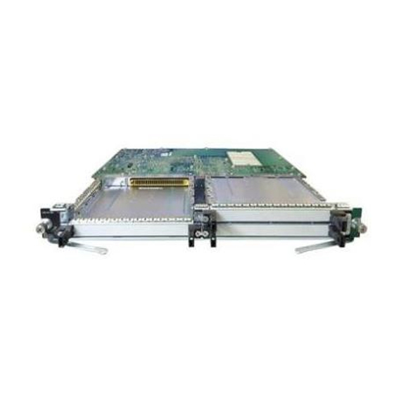
Fast Serial Interface Processor (FSIP)
Installation and Configuration
Product Numbers: CX-FSIP4=, CX-FSIP8=, PA-7KF-SPA=, UPG-FSIP4, UPG-FSIP8,
UPG-7KF-SPA
This configuration note contains instructions for installing and configuring the Fast Serial Interface
Processor (FSIP) in Cisco 7000 series or Cisco 7500 series routers. Included are basic configuration
steps and examples.
Note
yet developed. The Serial Interface Processor (SIP, SX-SIP, or PRE-FSIP) provided an interim
solution until the FSIP was released in September 1993 with Software Release 9.17(5). The FSIP is
now the default serial interface processor for Cisco 7000 series routers. The SIP can no longer be
ordered, and no new microcode or feature enhancements for it will be released. An FSIP upgrade
program is currently in progress to replace all SIPs in the field with new FSIPs. If you currently have
SIPs running in your Cisco 7000, we encourage you to replace them as soon as possible; the upgrade
is free of charge. Contact a service representative for information about the upgrade.
If you are replacing SIPs with new FSIPs, refer to the instructions in the document Replacing SIPs
with FSIPs in the Cisco 7000 (Document Number 78-1191-xx) before proceeding.
If you are installing a new FSIP in an installed Cisco 7000, ensure that your system meets the
required minimum configuration for FSIP operation before proceeding: Maintenance Release
9.17(5) and SP Microcode Version 1.4. (For a description of prerequisites, refer to the section
"Software Requirements" on page 6.)
Corporate Headquarters
Cisco Systems, Inc.
170 West Tasman Drive
San Jose, CA 95134-1706
USA
Copyright © 1993-1997
Cisco Systems, Inc.
All rights reserved.
DOC-781147=
78-1147-06
When the Cisco 7000 router was introduced in January 1993, the FSIP was planned, but not
1
Advertisement

Related Manuals for Cisco CX-FSIP8


Summary of Contents for Cisco CX-FSIP8
- Page 1 SIPs in the field with new FSIPs. If you currently have SIPs running in your Cisco 7000, we encourage you to replace them as soon as possible; the upgrade is free of charge. Contact a service representative for information about the upgrade.
- Page 2 If you are reading Cisco product documentation on the World Wide Web, you can submit comments electronically. Click Feedback in the toolbar, select Documentation, and click Enter the feedback form. After you complete the form, click Submit to send it to Cisco. We appreciate your comments.
- Page 3 — Cisco IOS Software Command Summary — Cisco Management Information Base (MIB) User Quick Reference • For hardware installation and maintenance information on the Cisco 7000 series and Cisco 7500 series routers, refer to the hardware installation and configuration documentation that shipped with your router.
- Page 4 FSIP Interface Types Additional port adapters are available as spares so that you can replace one that fails; however, you cannot upgrade a 4-port FSIP to an 8-port FSIP by adding port adapters. (The 4-port FSIP is not constructed to support additional ports after it leaves the factory; it contains the circuitry to control only one 4-port module.) An adapter cable provides the network connection for each port and determines the electrical interface type and mode of that interface.
- Page 5 Postal Telephone and Telegraph (PTT) networks. The E1-G.703/G.704 port adapter supports point-to-point connections to Cisco 7000 series and Cisco 7500 series routers from 2.048-Mbps, E1 leased-line services, and eliminates the need for a separate, external data termination unit that is typically used to convert standard serial interfaces, such as V.35, to E1-G.703/G.704.
-
Page 6: Software Requirements
Software Requirements The FSIP is compatible with any Cisco 7000 series router that is operating with the following software and microcode: •... -
Page 7: Safety Guidelines
In Cisco 7000 series routers, this partial boot is usually transparent to the user; however, it may generate a harmless error message if the system ROMs contain a software version earlier than Maintenance Release 9.17(5). - Page 8 FSIP Installation Prerequisites Dit waarschuwingssymbool betekent gevaar. U verkeert in een situatie die Waarschuwing lichamelijk letsel kan veroorzaken. Voordat u aan enige apparatuur gaat werken, dient u zich bewust te zijn van de bij elektrische schakelingen betrokken risico's en dient u op de hoogte te zijn van standaard maatregelen om ongelukken te voorkomen.
- Page 9 FSIP Installation Prerequisites Denna varningssymbol signalerar fara. Du befinner dig i en situation som kan leda till Varning! personskada. Innan du utför arbete på någon utrustning måste du vara medveten om farorna med elkretsar och känna till vanligt förfarande för att förebygga skador. Se förklaringar av de varningar som förkommer i denna publikation i dokumentet Regulatory Compliance and Safety Information (Efterrättelse av föreskrifter och säkerhetsinformation), vilket medföljer denna anordning.
- Page 10 1 and 10 megohms. Interface Processor Slot Locations The FSIP is installed in the interface processor slots in the Cisco 7000 series and Cisco 7500 series routers. The interface processor slots in the Cisco 7000 series and Cisco 7500 series routers are as follows: •...
- Page 11 FSIP Installation Prerequisites Figure 2 Cisco 7000 Interface Processor Slots Captive installation screw Upper power supply Captive installation screw Lower power supply Interface processor slots 7000 7000CI slot 5 slot 6 Figure 3 Cisco 7010 Interface Processor Slots RSP7000CI slot 4...
- Page 12 FSIP Installation Prerequisites Figure 4 Cisco 7505 Interface Processor Slots RSP slot Interface processor slot 3 Interface processor slot 2 Interface processor slot 1 Interface processor slot 0 Power switch DC OK LED Chassis grounding receptacles Power receptacle AC-input power supply...
- Page 13 FSIP Installation Prerequisites Figure 6 Cisco 7513 Interface Processor Slots Blower module Cable-management bracket Card cage and processor modules Interface processor slots 9 10 11 12 Guidelines for Interface Processor Removal and Installation This section describes the mechanical functions of system components and emphasizes the importance of following correct procedures to avoid unnecessary board failures.
- Page 14 FSIP Installation Prerequisites We recommend that you install interface processors starting with the slots closest to the RSPs Note and work out concentrically from there. This will help to ensure that rejection of electromagnetic interference (EMI) is maintained. All interface processors have ejector levers that allow you to firmly seat an interface processor in the interface processor slot (see Figure 8).
- Page 15 Note If you install or remove other interface processors in a Cisco 7000 series or Cisco 7500 series router with a CT3IP installed, you might have to reboot the system after the removal and replacement of that interface processor.
- Page 16 If you have a Cisco 7507 or a Cisco 7513 with an RSP2 configured as the system slave, we strongly recommend that you use the following procedure to remove and replace an interface processor: Remove the slave RSP2.
- Page 17 Cisco 7507 and Cisco 7513, we recommend that you install interface processors starting with the slots closest to the RSPs and work out concentrically from there. This will help prevent electromagnetic interference (EMI).
- Page 18 Interface Processor Replacement Procedures Use the following procedure to install an interface processor: Ensure that a console terminal is connected to the RP (or RSP) Console port and that the Step 1 console is turned on. Choose an available interface processor slot for the interface processor, and ensure that Step 2 the interface processor’s cable is of a sufficient length to connect the interface processor with any external equipment.
- Page 19 Interface Processor Replacement Procedures Figure 8 Location of Ejector Levers and Captive Installation Screws Interface processor card slot Ejector lever Interface processor card carrier guide (black) Captive installation screw Step 4 Hold the interface processor handle with one hand, and place your other hand under the carrier to support the interface processor (see Figure 7);...
- Page 20 FSIP Port Adapters, Interface Cables, and Connections Always use the ejector levers when installing or removing processor modules. A module Caution that is partially seated in the backplane will cause the system to hang and subsequently crash. Using the thumb and forefinger of each hand to pinch each ejector lever, simultaneously Step 7 push the top ejector lever down and the bottom ejector lever up until both are parallel to the faceplate.
- Page 21 FSIP Port Adapters, Interface Cables, and Connections The router (FSIP) end of all adapter cables is a 60-pin, D-shell plug that connects to the 60-pin port on the FSIP. The network end of the cable is an industry-standard connector for the type of electrical interface that the cable supports.
- Page 22 FSIP Port Adapters, Interface Cables, and Connections Figure 10 Synchronous Serial Port Adapter Cables Router (FSIP) connections EIA/TIA-232 EIA/TIA-449 V.35 X.21 EIA-530 Network connections at the modem or CSU/DSU 22 Fast Serial Interface Processor (FSIP) Installation and Configuration...
- Page 23 FSIP Port Adapters, Interface Cables, and Connections Figure 11, Figure 12, and Figure 13 show the unbalanced and balanced cables used for connecting the E1-G.703/G.704 port adapter and your network. The port-adapter end of each cable has a DB-15 connector. Figure 11 E1-G.703/G.704 Interface Cable for Unbalanced Connections (with BNC Connectors and Coaxial Cables)
- Page 24 FSIP Port Adapters, Interface Cables, and Connections All synchronous serial interface types except EIA-530 are available in DTE or DCE format: DTE with a plug connector at the network end and DCE with a receptacle at the network end. V.35 is available in either mode with either gender at the network end.
- Page 25 FSIP Port Adapters, Interface Cables, and Connections Table 4 EIA/TIA-449 Adapter Cable Signals DTE Cable DCE Cable FSIP End, FSIP End, Network Network End, 60-Position End, 60-Position DB-37 Plug DB-37 Plug Plug Receptacle Signal Signal Signal Signal Shield ground Shield Shield ground Shield ground ground...
- Page 26 FSIP Port Adapters, Interface Cables, and Connections Table 5 X.21 Adapter Cable Signals DTE Cable DCE Cable FSIP End, Network FSIP End, HD Network End, 60-Position End, 60-Position DB-15 Plug DB-15 Plug Plug Receptacle Signal Signal Signal Signal Shield ground Shield ground Shield ground Shield ground...
- Page 27 FSIP Port Adapters, Interface Cables, and Connections Table 6 V.35 Adapter Cable Signals DTE Cable DCE Cable FSIP End, Network FSIP End, End, Network End, 60-Position 34-Position 60-Position 34-Position Plug Plug Plug Receptacle Signal Signal Signal Signal Shield ground Frame ground Shield ground Frame ground Circuit ground...
- Page 28 FSIP Port Adapters, Interface Cables, and Connections Table 7 EIA-530 DTE Adapter Cable Signals FSIP End, HD Network End, 60-Position Plug DB-25 Plug Signal Signal Shield ground Shield ground TxD/RxD+ —> TxD+ TxD/RxD– —> TxD– RxD/TxD+ <— RxD+ RxD/TxD– <— RxC–...
- Page 29 FSIP Port Adapters, Interface Cables, and Connections Table 8 E1-G.703/G.704 Adapter Cable Connector Pinouts FSIP End Network End Null Modem DB-15 DB-15 DB-15 Twinax Signal Signal Signal Tx tip Tx tip Tx tip Tx ring Tx shield Ring Tx ring Tx shield –...
- Page 30 FSIP Port Adapters, Interface Cables, and Connections EIA/TIA-449 Connections EIA/TIA-449, which supports balanced (EIA/TIA-422) and unbalanced (EIA/TIA-423) transmissions, is a faster (up to 2 Mbps) version of EIA/TIA-232, which provides more functions and supports transmissions over greater distances. The EIA/TIA-449 standard was intended to replace EIA/TIA-232, but it was not widely adopted.
- Page 31 FSIP Port Adapters, Interface Cables, and Connections X.21 Connections The X.21 interface uses a 15-pin connection for balanced circuits and is commonly used in the United Kingdom to connect public data networks. The X.21 interface relocates some of the logic functions to the DTE and DCE interfaces and, as a result, requires fewer circuits and a smaller connector than EIA/TIA-232.
- Page 32 FSIP Port Adapters, Interface Cables, and Connections Metric Thumbscrews A pair of metric thumbscrews is included with each port adapter cable except V.35. If you plan to connect serial cables to a remote device that uses metric hardware, replace the standard 4-40 thumbscrews at the network end of the cable with the metric, M3 thumbscrews.
- Page 33 FSIP Port Adapters, Interface Cables, and Connections Attaching Network Interface Cables to the FSIP All FSIP ports support any available synchronous serial interface type and mode. The serial adapter cable determines the electrical interface type and mode of the port to which it is connected. E1-G.703/G.704, EIA/TIA-232, EIA/TIA-449, V.35, and X.21 interfaces are available in DTE mode with a plug at the network end and in DCE mode with a receptacle at the network end.
- Page 34 Using LEDs to Check FSIP Status Using LEDs to Check FSIP Status The FSIP has several status LEDs on its faceplate, next to each port, which indicate conditions on that port. (See Figure 22.) Figure 22 FSIP LEDs After system initialization, the enabled LED goes on to indicate that the FSIP has been enabled for operation.
- Page 35 Using LEDs to Check FSIP Status Figure 23 shows the signal flow between DTE and DCE devices and the LEDs that correspond to signals for each mode. Figure 23 DTE to DCE Signals Table 9 lists the LED states for ports in DTE and DCE mode; a more complete explanation follows. Table 9 FSIP LEDs DTE Signal...
- Page 36 Using LEDs to Check FSIP Status The following LED state descriptions include meanings for both DTE and DCE interfaces: • RxC—On both DTE and DCE interfaces, this LED is on when the port is receiving an external clock signal. • RxD—On both DTE and DCE interfaces, this LED is on when the port is receiving data signals (packets) from the network.
- Page 37 Interface Port Numbering for the FSIP Serial Interfaces Cisco 7000 series and Cisco 7500 series routers identify an interface address by its interface processor slot number and port number in the format slot/port. Each FSIP contains either four or eight serial interfaces.
- Page 38 Configuring the FSIP Configuring the Interfaces The following instructions are provided for performing a basic configuration: enabling an interface, specifying IP routing, and setting up external timing on a DCE interface. You might also need to enter other configuration subcommands, depending on the requirements for your system configuration and the protocols you plan to route on the interface.
- Page 39 Configuring the FSIP Configuring Timing (Clock) Signals All interfaces support both DTE and DCE mode (except the EIA/TIA-530 interface, which is DTE only). The mode of the interface cable attached to the port. To use a port as a DTE interface, you must connect a DTE adapter cable to the port.
- Page 40 Configuring the FSIP In the example that follows, the first serial port on an FSIP in interface processor slot 0 is configured to accept the internal clock signal: Router(config)# interface serial 0/0 Router(config-if)# transmit-clock-internal When the FSIP port is a DTE, the invert-transmit-clock command inverts the TxC signal it receives from the remote DCE.
- Page 41 Configuring the FSIP To enable 32-bit CRC on an interface, specify the slot and port address of the interface followed by the command crc32. In the example that follows, the first serial port on an FSIP in interface processor slot 0 is configured for 32-bit CRC: Router# configure terminal Enter configuration commands, one per line.
- Page 42 Configuring the FSIP Time slot 0, or the first 8 bits, is reserved as overhead. The remaining 248 bits (31 frames with 8 bits each) are designated time slots 1 through 31. Time slot 16 is also designated as a framing slot when using framed mode.
- Page 43 Configuring the FSIP In the example that follows, the first port on an FSIP in interface processor slot 0 is configured for CRC-4: Router# configure terminal Enter configuration commands, one per line. End with CNTL/Z. Router(config)# interface serial 0/0 Router(config-if)# crc4 Ctrl-Z To disable CRC and return an interface to the default of no CRC error checking, specify the interface and use the no crc4 command.
- Page 44 Configuring the FSIP Configuring E1-G.703/G.704 Loopback The E1-G.703/G.704 interface supports the same local loopback test as the other (data communications) FSIP interfaces. Loopback functions enable you to check the integrity of the physical data path between the FSIP and the E1 port adapter with the loopback command. The no loopback command disables all loopback tests on the interface.
- Page 45 Configuring the FSIP At system startup or restart, the FSIP polls the interfaces and determines the electrical interface type of each port (according to the type of port adapter cable attached). However, it does not necessarily repoll an interface when you change the adapter cable online. To ensure that the system recognizes the new interface type, shut down and reenable the interface after changing the cable.
- Page 46 Configuring the FSIP Using Show Commands to Check the Configuration The following summary describes how to use the show commands to verify that the new interfaces are configured correctly: Step 1 Use the show version command to display the system hardware configuration. Ensure that the list includes the new interfaces.
- Page 47 BPX, Catalyst, Cisco, Cisco Systems, the Cisco Systems logo, EtherChannel, FastHub, FastPacket, ForeSight, IPX, LightStream, OptiClass, Phase/IP, StrataCom, and StrataView Plus are registered trademarks of Cisco Systems, Inc. in the U.S. and certain other countries. All other trademarks mentioned in this document are the property of their respective owners.
- Page 48 Cisco Information Online 48 Fast Serial Interface Processor (FSIP) Installation and Configuration...