Cisco Catalyst 9300 Series Hardware Installation Manual
Hide thumbs
Also See for Catalyst 9300 Series:
- Hardware installation manual (140 pages) ,
- Installing (22 pages) ,
- Manual (15 pages)
Table of Contents
Advertisement
Advertisement
Table of Contents

Related Manuals for Cisco Catalyst 9300 Series


Summary of Contents for Cisco Catalyst 9300 Series
- Page 1 Cisco Catalyst 9300 Series Switches Hardware Installation Guide First Published: 2017-06-20 Last Modified: 2018-07-25 Americas Headquarters Cisco Systems, Inc. 170 West Tasman Drive San Jose, CA 95134-1706 http://www.cisco.com Tel: 408 526-4000 800 553-NETS (6387) Fax: 408 527-0883...
-
Page 2: Table Of Contents
Management Ports USB Type A Port Network Modules LEDs USB Console LED System LED Active LED STACK LED PoE LED XPS LED S-PWR LED Port LEDs and Modes Beacon LED Network Module LEDs Cisco Catalyst 9300 Series Switches Hardware Installation Guide... - Page 3 StackPower Partitioning Examples Installing the Switch Rack-Mounting Attaching the Rack-Mount Brackets Mounting the Switch a Rack Installing the Switch on a Table or Shelf After Switch Installation Connecting to the StackWise Ports Cisco Catalyst 9300 Series Switches Hardware Installation Guide...
- Page 4 Installing SFP, SFP+ and SFP28 Modules Removing SFP, SFP+ and SFP28 Modules Finding the Network Module Serial Number C H A P T E R 4 Installing a Power Supply Power Supply Modules Overview Installation Guidelines Cisco Catalyst 9300 Series Switches Hardware Installation Guide...
- Page 5 Installing the Cisco Microsoft Windows XP USB Driver Installing the Cisco Microsoft Windows 2000 USB Driver Installing the Cisco Microsoft Windows Vista and Windows 7 USB Driver Uninstalling the Cisco Microsoft Windows USB Driver Uninstalling the Cisco Microsoft Windows XP and 2000 USB Driver...
- Page 6 A P P E N D I X B Connector and Cable Specifications Connector Specifications 10/100/1000 Ports (Including PoE) SFP Module Connectors Console Port Cables and Adapters StackWise Cables SFP Module Cables Cable Pinouts Console Port Adapter Pinouts Cisco Catalyst 9300 Series Switches Hardware Installation Guide...
- Page 7 Any use of actual IP addresses or phone numbers in illustrative content is unintentional and coincidental. Cisco and the Cisco logo are trademarks or registered trademarks of Cisco and/or its affiliates in the U.S. and other countries. To view a list of Cisco trademarks, go to this URL: www.cisco.com trademarks.
-
Page 9: Preface
A vertical line, called a pipe, indicates a choice within a set of keywords or arguments. [x | y] Optional alternative keywords are grouped in brackets and separated by vertical bars. {x | y} Required alternative keywords are grouped in braces and separated by vertical bars. Cisco Catalyst 9300 Series Switches Hardware Installation Guide... - Page 10 Use the statement number provided at the end of each warning to locate its translation in the translated safety warnings that accompanied this device. Statement 1071 SAVE THESE INSTRUCTIONS Cisco Catalyst 9300 Series Switches Hardware Installation Guide...
-
Page 11: Related Documentation
Obtaining Documentation and Submitting a Service Request For information on obtaining documentation, submitting a service request, and gathering additional information, see the monthly What's New in Cisco Product Documentation, which also lists all new and revised Cisco technical documentation, at: http://www.cisco.com/c/en/us/td/docs/general/whatsnew/whatsnew.html... - Page 12 Preface Obtaining Documentation and Submitting a Service Request Cisco Catalyst 9300 Series Switches Hardware Installation Guide...
-
Page 13: Product Overview
C H A P T E R Product Overview Cisco Catalyst 9300 Series Switches family is the stackable enterprise switching platform built for Security, IoT, Mobility, and Cloud. It has the most flexible uplink architecture with support for 1G, 10G, and 40G. -
Page 14: Front Panel Components
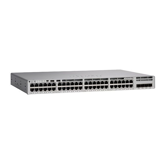
1100 WAC power supply; supports StackWise-480 and StackPower. Front Panel Components This section describes the front panel components of a Cisco Catalyst 9300 Series switch: • 24 or 48 downlink ports of one of these types: • 10/100/1000 • 10/100/1000 PoE+ •... - Page 15 All the switch models have similar components. See the following illustration for example. Note The Catalyst 9300 switches might have slight cosmetic differences on the bezels. Figure 1: C9300-48P Switch Front Panel Cisco Catalyst 9300 Series Switches Hardware Installation Guide...
-
Page 16: 10/100/1000 Ports
The 10BASE-T traffic can use Category 3 cable or higher. PoE, PoE+, and Cisco UPoE Ports The PoE+ and Cisco Universal Power Over Ethernet (Cisco UPoE) ports use the same connectors as described 10/100/1000 Port Connections, on page 39. -
Page 17: Multigigabit Ports
Power Supply Modules, on page 15 for the power supply matrix that defines the available PoE, PoE+, and Cisco UPOE power per port. The output of the PoE+ or UPOE circuit has been evaluated as a Limited Power Source (LPS) per IEC 60950-1. -
Page 18: Usb Type A Port
The port supports Cisco USB flash drives with capacities from 128 MB to 8 GB (USB devices with port densities of 128 MB, 256 MB, 1 GB, 4 GB, and 8 GB are supported). When combined with stacking, you can upgrade other switches in the stack from an USB key inserted in any switch within the stack. -
Page 19: Leds
The following table lists the optional Cisco Catalyst 9300 uplink network modules with 1-Gigabit, 10-Gigabit and 25-Gigabit slots. In addition, Cisco Catalyst 9300 Series switches also support 3850 uplink network modules. For the complete list of supported network modules, see... -
Page 20: System Led
This figure shows the LEDs on for each switch. When you press the Mode button to select the STACK LED, the corresponding port LEDs will blink green for each switch. For example, for switch 1, port 1 will blink Cisco Catalyst 9300 Series Switches Hardware Installation Guide... -
Page 21: Poe Led
LED blinks green to show that this is switch 3 in the stack. PoE LED The PoE LED indicates the status of the PoE mode: either PoE, PoE+, or Cisco UPOE. Table 6: PoE LED Color Description PoE mode is not selected. None of the 10/100/1000 ports have been denied power or are in a fault condition. -
Page 22: Xps Led
The power supply in a switch has failed, and the XPS is providing power to that switch (redundancy has been allocated to this device). For information about the XPS 2200, see the Cisco eXpandable Power System 2200 Hardware Installation Guide on Cisco.com: http://www.cisco.com/go/xps2200_hw... -
Page 23: Port Leds And Modes
Port is blocked by Spanning Tree Protocol (STP) and is not forwarding data. After a port is reconfigured, the port LED can be amber for up to 30 seconds as STP checks the switch for possible loops. Cisco Catalyst 9300 Series Switches Hardware Installation Guide... - Page 24 STACK (stack No stack member corresponding to that member number. member) Blinking green Stack member number. Green Member numbers of other stack member switches. Cisco Catalyst 9300 Series Switches Hardware Installation Guide...
-
Page 25: Beacon Led
Network Module Link Status Link is off. Green Link is on; no activity. Blinking green Activity on a link; no faults. Note The LED will blink green even when there is very little control traffic. Cisco Catalyst 9300 Series Switches Hardware Installation Guide... -
Page 26: Rear Panel
Link is off due to a fault or because it has exceeded a limit set in the switch software. Caution Link faults occur when noncompliant cabling is connected to an SFP/SFP+/SFP28 port. Use only standard-compliant cabling to connect to Cisco SFP/SFP+/SFP28 ports. You must remove from the network any cable or device that causes a link fault. -
Page 27: Rj-45 Console Port Led
Connecting to the StackWise Ports, on page Caution Use only approved cables, and connect only to similar Cisco equipment. Equipment might be damaged if connected to nonapproved Cisco cables or equipment. Power Supply Modules The switches are powered through one or two internal power supply modules. - Page 28 2.5Gbps Cisco UPOE 48 Multigigabit Cisco UPOE 5G PWR-C1-1100WAC-P 645 W switch Table 13: Switch Power Supply Requirements for PoE, PoE+, and Cisco UPoE PoE Option 24-Port Switch 48-Port Switch PoE (up to 15.4 W per port) (1) 715 W...
-
Page 29: Fan Module
The following illustration shows the airflow pattern for the switches. The blue arrow shows cool airflow, and the red arrow shows warm airflow. For information about installing a fan module and fan specifications, see Installing a Fan Module, on page Cisco Catalyst 9300 Series Switches Hardware Installation Guide... -
Page 30: Stackpower Connector
StackPower Connector StackPower Connector The switches have a StackPower connector for use with Cisco StackPower cables to configure a switch power stack that includes up to four switches. A switch power stack can be configured in redundant or power-sharing mode. -
Page 31: Network Configurations
See the switch software configuration guide for network configuration concepts and examples of using the switch to create dedicated network segments and interconnecting the segments through Fast Ethernet and Gigabit Ethernet connections. Cisco Catalyst 9300 Series Switches Hardware Installation Guide... - Page 32 Product Overview Network Configurations Cisco Catalyst 9300 Series Switches Hardware Installation Guide...
-
Page 33: Switch Installation
Statement 43 Warning Do not stack the chassis on any other equipment. If the chassis falls, it can cause severe bodily injury and equipment damage. Statement 48 Cisco Catalyst 9300 Series Switches Hardware Installation Guide... - Page 34 Ultimate disposal of this product should be handled according to all national laws and regulations. Statement 1040 Warning To prevent the system from overheating, do not operate it in an area that exceeds the maximum recommended ambient temperature of: <113°F (45°C). Statement 1047 Cisco Catalyst 9300 Series Switches Hardware Installation Guide...
-
Page 35: Installation Guidelines
• Cooling mechanisms, such as fans and blowers in the switch, can draw dust and other particles causing contaminant buildup inside the chassis, which can result in system malfunction. You must install this Cisco Catalyst 9300 Series Switches Hardware Installation Guide... -
Page 36: Shipping Box Contents
Some components are optional, depending on your order. Note Verify that you have received these items. If any item is missing or damaged, contact your Cisco representative or reseller for instructions. Verify that you have received these items. If any item is missing or damaged, contact your Cisco representative or reseller for instructions. -
Page 37: Tools And Equipment
When you connect the RPS to the switch, put the RPS in standby mode. Set the RPS to active mode during normal operation. Warning Attach only the following Cisco external power system to the switch: Cisco XPS 2200 Statement 387 Planning a Switch Data Stack Cisco Catalyst 9300 switches can share bandwidth by using data stacking. -
Page 38: Switch Stacking And Power Stacking Guidelines
If you do not specify the length of the StackWise cable, the 0.5-meter cable is supplied. If you need the 1-meter cable or the 3-meter cable, you can order it from your Cisco supplier. For cable part numbers, StackWise Ports, on page 15. - Page 39 If the bottom switch is a member (not active or standby switch), it reloads. Figure 14: Example of a Partitioned Data Stack with a Failover Condition Cisco Catalyst 9300 Series Switches Hardware Installation Guide...
-
Page 40: Power-On Sequence For Switch Stacks
For conditions that can cause a stack reelection or to manually elect the active switch, see the stacking software configuration guide on Cisco.com at this URL: http://www.cisco.com/go/c9300. Cisco Catalyst 9300 Series Switches Hardware Installation Guide... -
Page 41: Planning A Stackpower Stack
• Length of cable. Depending on the configurations that you have, you might need different-sized cables. If you do not specify the length of the StackPower cable, the 0.3 meter cable is supplied. If you need the 1.5 meter cable, you can order it from your Cisco supplier. For cable part numbers, see StackPower Connector, on page 18. - Page 42 StackPower Cable 1.5 meter Figure 15: StackPower Cable for Use with Cisco Catalyst 9300 Series Switches This figure shows a ring configuration using both of the supplied 0.3-meter StackPower cables and one 1.5-meter cable. In the examples that follow, the switches are stacked in a vertical rack or on a table.
-
Page 43: Stackpower Partitioning Examples
In this figure, StackPower port B on the center switch has failed and this stack partitions into two stacks. The top two switches share power, and the bottom switch is now a separate stack. Cisco Catalyst 9300 Series Switches Hardware Installation Guide... -
Page 44: Installing The Switch
• When mounting this unit in a partially filled rack, load the rack from the bottom to the top with the heaviest component at the bottom of the rack. • If the rack is provided with stabilizing devices, install the stabilizers before mounting or servicing the unit in the rack. Statement 1006 Cisco Catalyst 9300 Series Switches Hardware Installation Guide... - Page 45 This figure shows the standard 19-inch brackets and other optional mounting brackets. You can order the optional brackets (ACC-KIT-T1=) from your Cisco sales representative. 19-inch brackets 23-inch brackets (RACK-KIT-T1=) (RACK-KIT-T1=) Extension rails and 24-inch brackets brackets for four-point (RACK-KIT-T1=) mounting, includes 19-inch brackets (4PT-KIT-T1=) ETSI brackets (RACK-KIT-T1=) Cisco Catalyst 9300 Series Switches Hardware Installation Guide...
-
Page 46: Attaching The Rack-Mount Brackets
Use the four supplied Phillips machine screws to attach the brackets to the rack. Step 2 Use the black Phillips machine screw to attach the cable guide to the left or right bracket. Cisco Catalyst 9300 Series Switches Hardware Installation Guide... -
Page 47: Installing The Switch On A Table Or Shelf
• Configure the switch. For more information, see Setting up the Switch, on page • Connect to the stack ports. • Install the power cord retainer (optional). • Connect to the front-panel ports. Cisco Catalyst 9300 Series Switches Hardware Installation Guide... -
Page 48: Connecting To The Stackwise Ports
Connect the cable to the StackWise port on the switch rear panel. Align the connector and connect the StackWise cable to the StackWise port on the switch rear panel and finger-tighten the screws (clockwise direction). Make sure the Cisco logo is on the top side of the connector as shown in the figure. Step 3 Connect the other end of the cable to the port on the other switch and finger-tighten the screws. - Page 49 (installing and removing it up to 200 times is supported). When you need to remove the StackWise cable from the connector, make sure to fully unscrew the correct screws. When the connectors are not being used, replace the dust covers. Cisco Catalyst 9300 Series Switches Hardware Installation Guide...
-
Page 50: Connecting To The Stackpower Ports
Planning a Switch Data Stack, on page 25. Always use a Cisco-approved StackWise cable to connect the switches. To prevent misconfiguration, the StackPower ports on the switch are keyed and have colored bands that match the keying and bands on the StackPower cable connectors. -
Page 51: 10/100/1000 Port Connections
PoE inline power supports devices compliant with the IEEE 802.3af standard, as well as prestandard Cisco IP Phones and Cisco Aironet Access Points. Each port can deliver up to 15.4 W of PoE. PoE+ inline power supports devices compliant with the IEEE 802.3at standard, by delivering up to 30 W of PoE+ power per port to all switch ports. - Page 52 Noncompliant cabling or powered devices can cause a PoE port fault. Use only standard-compliant cabling to connect Cisco prestandard IP Phones and wireless access points, IEEE 802.3af, or 802.3at (PoE+)-compliant devices. You must remove any cable or device that causes a PoE fault.
-
Page 53: Installing A Network Module
SFP, SFP+ and SFP28 Modules, on page 51 • Finding the Network Module Serial Number, on page 53 Network Modules Overview The Cisco Catalyst 9300 Series Switches supports the following optional network modules for uplink ports. Network Module Description C9300-NM-4G This module has four 1G SFP module slots. -
Page 54: Installing A Network Module In The Switch
Safety Warnings This section includes the installation cautions and warnings. Translations of the safety warnings appear in the Regulatory Compliance and Safety Information for Cisco Catalyst 9300 Series Switches on Cisco.com: http://www.cisco.com/go/c9300. Read this section before you install a network module. -
Page 55: Installing Network Modules
• Removing and installing a network module can shorten its useful life. Do not remove and insert a network module more often than is necessary. • To prevent ESD damage, follow your normal board and component handling procedures when connecting cables to the switch and other devices. Cisco Catalyst 9300 Series Switches Hardware Installation Guide... - Page 56 Position the module face up to install it in the module slot. Slide the module into the slot until the back of the module faceplate is flush with the switch faceplate. Fasten the captive screws to secure the network module in place. Cisco Catalyst 9300 Series Switches Hardware Installation Guide...
-
Page 57: Network Module Port Configurations
Table 18: C9300-NM-2Q Module with 40G QSFP Module Interface Action FortyGigabitEthernet1/1/1 Configure this interface FortyGigabitEthernet1/1/2 Configure this interface TenGigabitEthernet1/1/1 Disregard TenGigabitEthernet1/1/2 Disregard TenGigabitEthernet1/1/3 Disregard TenGigabitEthernet1/1/4 Disregard TenGigabitEthernet1/1/5 Disregard TenGigabitEthernet1/1/6 Disregard TenGigabitEthernet1/1/7 Disregard TenGigabitEthernet1/1/8 Disregard Cisco Catalyst 9300 Series Switches Hardware Installation Guide... -
Page 58: C9300-Nm-4G Module
TenGigabitEthernet1/1/2 Configure this interface TenGigabitEthernet1/1/3 Configure this interface TenGigabitEthernet1/1/4 Configure this interface C9300-NM-2Y Module Table 21: C9300-NM-2Y Module with 25G SFP28 Module Interface Action TwentyFiveGigabitEthernet1/1/1 Configure this interface TwentyFiveGigabitEthernet1/1/2 Configure this interface Cisco Catalyst 9300 Series Switches Hardware Installation Guide... -
Page 59: C9300-Nm-8X Module
CLI. Table 23: C3850-NM-4-1G Module Interface Action GigabitEthernet1/1/1 Configure this interface GigabitEthernet1/1/2 Configure this interface GigabitEthernet1/1/3 Configure this interface GigabitEthernet1/1/4 Configure this interface TenGigabitEthernet1/1/1 Disregard TenGigabitEthernet1/1/2 Disregard TenGigabitEthernet1/1/3 Disregard TenGigabitEthernet1/1/4 Disregard Cisco Catalyst 9300 Series Switches Hardware Installation Guide... -
Page 60: C3850-Nm-4-10G Module
Configure this interface GigabitEthernet1/1/2 Configure this interface GigabitEthernet1/1/3 Disregard GigabitEthernet1/1/4 Disregard TenGigabitEthernet1/1/1 Disregard TenGigabitEthernet1/1/2 Disregard TenGigabitEthernet1/1/3 Configure this interface, even when operating as 1-G TenGigabitEthernet1/1/4 Configure this interface, even when operating as 1-G Cisco Catalyst 9300 Series Switches Hardware Installation Guide... -
Page 61: C3850-Nm-8-10G Module
Table 27: C3850-NM-2-40G Module with 40 G QSFP Module Interface Action FortyGigabitEthernet1/1/1 Configure this interface FortyGigabitEthernet1/1/2 Configure this interface TenGigabitEthernet1/1/1 Disregard TenGigabitEthernet1/1/2 Disregard TenGigabitEthernet1/1/3 Disregard TenGigabitEthernet1/1/4 Disregard TenGigabitEthernet1/1/5 Disregard TenGigabitEthernet1/1/6 Disregard TenGigabitEthernet1/1/7 Disregard TenGigabitEthernet1/1/8 Disregard Cisco Catalyst 9300 Series Switches Hardware Installation Guide... -
Page 62: Removing A Network Module
Step 2 Disconnect the cables from the SFP/SFP+/SFP28/QSFP module. Step 3 Remove the SFP/SFP+/SFP28/QSFP modules from the network module. Step 4 Loosen the captive screws that hold the network module in place. Cisco Catalyst 9300 Series Switches Hardware Installation Guide... -
Page 63: Sfp, Sfp+ And Sfp28 Modules
You must have an installed network module to use SFP, SFP+ and SFP28 modules. See the switch release notes on Cisco.com for the list of supported SFP, SFP+ and SFP28 modules. Use only supported SFP/SFP+/SFP28 modules on the switch. For the latest information about supported SFP, SFP+ and SFP28... - Page 64 If the module has a bale-clasp latch, close it to lock the SFP/SFP+/SFP28 module in place. Step 6 Remove the SFP/SFP+/SFP28 dust plugs and save. Step 7 Connect the SFP/SFP+/SFP28 cables. Figure 26: Network Module with SFP/SFP+/SFP28 Modules Installed Cisco Catalyst 9300 Series Switches Hardware Installation Guide...
-
Page 65: Removing Sfp, Sfp+ And Sfp28 Modules
Place the SFP/SFP+/SFP28 module in an antistatic bag or other protective environment. Finding the Network Module Serial Number If you contact Cisco Technical Assistance regarding a network module, you need to know its serial number. Figure 27: Network Module Serial Number Location... - Page 66 Installing a Network Module Finding the Network Module Serial Number Cisco Catalyst 9300 Series Switches Hardware Installation Guide...
-
Page 67: Installing A Power Supply
Each AC power supply module has a power cord for connection to an AC power outlet. The 1100-W and 715-W modules use a 16-AWG cord (only North America). All other modules use an 18-AWG cord. The following illustrations show the power supply modules. Cisco Catalyst 9300 Series Switches Hardware Installation Guide... - Page 68 AC power cord connector Figure 29: 715-W AC Power Supply 715-W AC power supply Release latch module AC OK LED Power cord retainer PS OK LED Keying feature AC power cord connector Cisco Catalyst 9300 Series Switches Hardware Installation Guide...
-
Page 69: Installation Guidelines
(AC LED is off). Green AC input power present. Green Power output to switch active. Output has failed. Installation Guidelines Observe these guidelines when removing or installing a power supply or fan module: Cisco Catalyst 9300 Series Switches Hardware Installation Guide... - Page 70 Do not reach into a vacant slot or chassis while you install or remove a module. Exposed circuitry could constitute an energy hazard. Statement 206 Warning Only trained and qualified personnel should be allowed to install, replace, or service this equipment. Statement 1030 Cisco Catalyst 9300 Series Switches Hardware Installation Guide...
-
Page 71: Installing Or Replacing An Ac Power Supply
Installing a Power Supply Installing or Replacing an AC Power Supply Warning If a Cisco external power system is not connected to the switch, install the provided connector cover on the back of the switch. Statement 386 Installing or Replacing an AC Power Supply... -
Page 72: Finding The Power Supply Module Serial Number
Finding the Power Supply Module Serial Number If you contact Cisco Technical Assistance regarding a power supply module, you need to know the serial number. See the following illustrations to find the serial number. You can also use the CLI to find out the serial number. - Page 73 Installing a Power Supply Finding the Power Supply Module Serial Number Figure 35: 715-W and 350-W AC Power Supply Serial Number Cisco Catalyst 9300 Series Switches Hardware Installation Guide...
- Page 74 Installing a Power Supply Finding the Power Supply Module Serial Number Cisco Catalyst 9300 Series Switches Hardware Installation Guide...
-
Page 75: Fan Modules Overview
The switch can operate with two operational fans and one nonfunctional fan, but the failed fan should be replaced as soon as possible to avoid a service interruption due to a second fan fault. Figure 36: Fan Module Fan LED Retainer clip Exhaust vent Extraction handles Cisco Catalyst 9300 Series Switches Hardware Installation Guide... -
Page 76: Installation Guidelines
When the fan is operating, a green LED is on in the top left corner of the fan. Do not reach into a vacant slot when installing or removing a module. Exposed circuitry is an energy Warning hazard. Statement 206 Cisco Catalyst 9300 Series Switches Hardware Installation Guide... -
Page 77: Finding The Fan Module Serial Number
Finding the Fan Module Serial Number If you contact Cisco Technical Assistance regarding a fan module, you need to know the fan module serial number. See the following illustration to find the serial number. - Page 78 Installing a Fan Module Finding the Fan Module Serial Number Cisco Catalyst 9300 Series Switches Hardware Installation Guide...
-
Page 79: Configuring The Switch Using The Web User Interface
Connect one end of an ethernet cable to one of the uplink (non-management) ports on the active supervisor and the other end of the ethernet cable to the host (PC). Step 3 Set up your PC as a DHCP client, to obtain the IP address of the switch automatically. Cisco Catalyst 9300 Series Switches Hardware Installation Guide... -
Page 80: Creating User Accounts
Set a password of up to 25 alphanumeric characters. The username password combination you set gives you privilege 15 access. The string cannot start with a number, is case sensitive, and allows spaces but ignores leading spaces. Cisco Catalyst 9300 Series Switches Hardware Installation Guide... - Page 81 Configuring the Switch Creating User Accounts Figure 39: Create Account Cisco Catalyst 9300 Series Switches Hardware Installation Guide...
-
Page 82: Choosing Setup Options
Choose the date and time settings for your device. To synchronize your device with a valid outside timing mechanism, such as an NTP clock source, choose Automatic, or choose Manual to set it yourself. Cisco Catalyst 9300 Series Switches Hardware Installation Guide... - Page 83 If you did not select Wired Network, in the earlier step, continue to the next screen to verify your configuration on the Day 0 Config Summary screen, and click Finish. To automatically configure your device based on a site profile, click Setup Options, and select Wired Network. Cisco Catalyst 9300 Series Switches Hardware Installation Guide...
-
Page 84: Configuring Your Device Based On A Site Profile
To ease your configuration tasks and save time, choose a site profile based on where your device may be installed and managed in your network. Based on the site profile you choose, your device is automatically Cisco Catalyst 9300 Series Switches Hardware Installation Guide... - Page 85 Configuring the Switch Configuring Your Device Based on a Site Profile configured according to Cisco best practices. You can easily modify this default configuration, from the corresponding detailed configuration screens. Choosing a site profile as part of Quick Setup allows you to configure your device based on the business needs of your enterprise.
- Page 86 VLANs. Downlink Interfaces Downlink ports Downlink ports Downlink ports configured in Access configured in Access configured in Access mode mode mode Port-channel Not configured Port-channel to Port-channel to distribution created distribution created Cisco Catalyst 9300 Series Switches Hardware Installation Guide...
- Page 87 Configuring the Switch Configuring Your Device Based on a Site Profile Figure 42: Site Profile - Access Switches Cisco Catalyst 9300 Series Switches Hardware Installation Guide...
- Page 88 The hostname or device The hostname or device name you provided as part name you provided as part name you provided as part of Quick Setup of Quick Setup of Quick Setup Cisco Catalyst 9300 Series Switches Hardware Installation Guide...
- Page 89 Trunk mode configured in Trunk mode configured in Trunk mode Port-channel Port-channel to core Port-channel to core or Port-channel to core or created access created distribution created Cisco Catalyst 9300 Series Switches Hardware Installation Guide...
- Page 90 Configuring the Switch Configuring Your Device Based on a Site Profile Figure 44: Site Profile - Distribution Switches Cisco Catalyst 9300 Series Switches Hardware Installation Guide...
- Page 91 (with ECMP Peer and Port Channel Downlink) Hostname The hostname or device name you The hostname or device name you provided as part of Quick Setup provided as part of Quick Setup UDLD Enabled Enabled Cisco Catalyst 9300 Series Switches Hardware Installation Guide...
- Page 92 MAN/WAN device MAN/WAN device Downlink Interfaces Downlink connections to access Downlink connections to switches distribution switches Cross-connect Interfaces Selected ports connect to other core Selected ports connect to other core switches switches Cisco Catalyst 9300 Series Switches Hardware Installation Guide...
-
Page 93: Configuring Switch Wide Settings
Figure 46: Site Profile - Core Switches Configuring Switch Wide Settings Configuring VLAN Settings Procedure Step 1 In the VLAN Configuration section, you can configure both data and voice VLANs. Type a name for your data VLAN. Cisco Catalyst 9300 Series Switches Hardware Installation Guide... -
Page 94: Configure Stp Settings
RPVST is the default STP mode configured on your device. You can change it to PVST from the STP Mode drop-down list. Step 2 To change a bridge priority number from the default value 32748, change Bridge Priority to Yes and choose a priority number from the drop-down list. Cisco Catalyst 9300 Series Switches Hardware Installation Guide... -
Page 95: Configuring Dhcp, Ntp, Dns And Snmp Settings
In the Domain Details section, enter a domain name that the software uses to complete unqualified hostnames. Step 2 Type an IP address to identify the DNS server. This server is used for name and address resolution on your device. Cisco Catalyst 9300 Series Switches Hardware Installation Guide... - Page 96 In the Management Details section, type an IP address to identify the SNMP server. SNMPv1, SNMPv2, and SNMPv3 are supported on your device. Step 7 Specify the SNMP community string to permit access to the SNMP protocol. Figure 48: DHCP, NTP, DNS and SNMP Settings Cisco Catalyst 9300 Series Switches Hardware Installation Guide...
-
Page 97: Configuring Port Settings
Choose an option from the Select Switch drop-down list. Step 3 Make selections from the Available list of interfaces based on how you want to enable them and move them to the Enabled list. Cisco Catalyst 9300 Series Switches Hardware Installation Guide... - Page 98 Configuring the Switch Configuring Port Settings Figure 49: Port Settings What to do next • Click Day 0 Config Summary to verify your setup. • Click Finish. Cisco Catalyst 9300 Series Switches Hardware Installation Guide...
-
Page 99: Configuring The Switch Using The Cli
You can access the CLI on a configured or unconfigured switch by connecting the RJ-45 console port or USB console port of the switch to your PC or workstation and accessing the switch through a terminal emulation program. Cisco Catalyst 9300 Series Switches Hardware Installation Guide... -
Page 100: Connecting The Rj-45 Console Port
If you are connecting the switch USB console port to a Windows-based PC for the first time, install the USB driver. See Installing the Cisco Microsoft Windows USB Device Driver, on page Note USB Type A port on the switch provides file system support and is NOT a console port. See USB Type A Port section. -
Page 101: Installing The Cisco Microsoft Windows Usb Device Driver
Installing the Cisco Microsoft Windows XP USB Driver Procedure Step 1 Obtain the Cisco USB console driver file from the Cisco.com web site and unzip it. Note You can download the driver file from the Cisco.com site for downloading the switch software. -
Page 102: Installing The Cisco Microsoft Windows 2000 Usb Driver
Installing the Cisco Microsoft Windows 2000 USB Driver Procedure Step 1 Obtain the Cisco USB console driver file from the Cisco.com web site and unzip it. You can download the driver file from the Cisco.com site for downloading the switch software. Note Step 2 Double-click the setup.exe file. -
Page 103: Uninstalling The Cisco Microsoft Windows Vista And Windows 7 Usb Driver
Scroll to Cisco Virtual Com and click Remove. Step 3 When the Program Maintenance window appears, select the Remove radio button. Click Next. Uninstalling the Cisco Microsoft Windows Vista and Windows 7 USB Driver Before you begin Disconnect the switch console terminal before uninstalling the driver. - Page 104 Configuring the Switch Uninstalling the Cisco Microsoft Windows Vista and Windows 7 USB Driver Step 5 When the InstallShield Wizard Completed window appears, click Finish. Cisco Catalyst 9300 Series Switches Hardware Installation Guide...
-
Page 105: Technical Specifications
23°F to 113°F (–5°C to 45°C) up to 5000 feet (1500m) 23°F to 104°F (–5°C to 40ºC) up to 10,000 feet (3000m) Storage temperature –40 to 158°F (–40 to 70°C) Relative humidity 10 to 90% (noncondensing) Cisco Catalyst 9300 Series Switches Hardware Installation Guide... - Page 106 16.63 lb (7.54 kg) C9300-48T 16.43 lb (7.45 kg) C9300-48P 16.73 lb (7.59 kg) C9300-48U 17.03 lb (7.72 kg) C9300-24UX 18.18 lb (8.25 kg) C9300-48UXM 20.6 lb (9.34 kg) C9300-48UN 20.2 lb (9.16 kg) Cisco Catalyst 9300 Series Switches Hardware Installation Guide...
-
Page 107: Specifications For The Power Supplies, Switches, And Fan
Input voltage and Frequency • PWR-C1-1100WAC and PWR-C1-1100WAC-P: 1100-W, 115 to 240 VAC (autoranging) 50-60 • PWR-C1-715WAC: 715 W, 100 to 240 VAC(autoranging) 50-60 Hz • PWR-C1-350WAC: 350 W, 100 to 240 VAC(autoranging) 50-60 Hz Cisco Catalyst 9300 Series Switches Hardware Installation Guide... - Page 108 23 to 176°F (–5 to 80°C) Storage temperature –40 to 185°F (–40 to 85°C) up to 15,000 ft (4500 m) Relative humidity 5 to 95% (noncondensing) Altitude Up to 13,000 ft (4000 m) Physical Specification Cisco Catalyst 9300 Series Switches Hardware Installation Guide...
- Page 109 Technical Specifications Dimensions (H x D x W) 1.62 x 1.73 x 4.24 in. (4.11 x 4.39 x 10.76 cm) Weight (for three fans) 0.48 lb (0.21 kg) Operating Specification Airflow 20 cfm Cisco Catalyst 9300 Series Switches Hardware Installation Guide...
- Page 110 Technical Specifications Technical Specifications Cisco Catalyst 9300 Series Switches Hardware Installation Guide...
-
Page 111: Connector And Cable Specifications
Cables and Adapters, on page 101 Connector Specifications 10/100/1000 Ports (Including PoE) All 10/100/1000 ports use standard RJ-45 connectors and Ethernet pinouts. Figure 51: 10/100/1000 Port Pinouts SFP Module Connectors Figure 52: Duplex LC Cable Connector Cisco Catalyst 9300 Series Switches Hardware Installation Guide... -
Page 112: Console Port
The USB console port uses a USB Type A to 5-pin mini-Type B cable. The USB Type A-to-USB mini-Type B cable is not supplied. You can order an accessory kit (part number 800-33434) that contains this cable. Figure 56: USB Type A-to-USB 5-Pin Mini-Type B Cable Cisco Catalyst 9300 Series Switches Hardware Installation Guide... -
Page 113: Cables And Adapters
Cables and Adapters StackWise Cables You can order these StackWise cables (nonhalogen) from your Cisco sales representative: • STACK-T1-50CM= (0.5-meter cable) • STACK-T1-1M= (1-meter cable) • STACK-T1-3M= (3-meter cable) -
Page 114: Cable Pinouts
The wire connected to the pin on the outside of the left plug should be a different color from the wire connected to the pin on the inside of the right plug. Cisco Catalyst 9300 Series Switches Hardware Installation Guide... -
Page 115: Console Port Adapter Pinouts
Switch Console Port (DTE) RJ-45-to-DB-9 Terminal Adapter Console Device Signal DB-9 Pin Signal Table 42: Console Port Signaling with a DB-25 Adapter Switch Console Port (DTE) RJ-45-to-DB-25 Terminal Adapter Console Device Signal DB-25 Pin Signal Cisco Catalyst 9300 Series Switches Hardware Installation Guide... - Page 116 Connector and Cable Specifications Connector and Cable Specifications Switch Console Port (DTE) RJ-45-to-DB-25 Terminal Adapter Console Device Signal DB-25 Pin Signal Cisco Catalyst 9300 Series Switches Hardware Installation Guide...