Table of Contents
Advertisement
Quick Links
PA-4T+ Synchronous Serial Port Adapter
Installation and Configuration
Product Number: PA-4T+=
Platforms Supported: Catalyst 5000 Family Switches with RSM/VIP2, Catalyst 6000
Family Switches with Catalyst 6000 Family FlexWAN Module, Cisco 7100 Series
Routers, Cisco 7200 Series Routers, Cisco 7200 VXR Routers, Cisco uBR7200 Series
Routers, Cisco 7201 Router, Cisco 7301 Router, Cisco 7304 PCI Port Adapter Carrier
Card in the Cisco 7304 Router, Cisco 7401ASR Router, and VIP in the Cisco 7000 Series
and Cisco 7500 Series Routers
Americas Headquarters
Cisco Systems, Inc.
170 West Tasman Drive
San Jose, CA 95134-1706
USA
http://www.cisco.com
Tel: 408 526-4000
800 553-NETS (6387)
Fax: 408 527-0883
Text Part Number: OL-3561-04
Advertisement
Table of Contents

Related Manuals for Cisco PA-4T+


Summary of Contents for Cisco PA-4T+
- Page 1 Routers, Cisco 7200 Series Routers, Cisco 7200 VXR Routers, Cisco uBR7200 Series Routers, Cisco 7201 Router, Cisco 7301 Router, Cisco 7304 PCI Port Adapter Carrier Card in the Cisco 7304 Router, Cisco 7401ASR Router, and VIP in the Cisco 7000 Series and Cisco 7500 Series Routers Americas Headquarters Cisco Systems, Inc.
- Page 2 You can determine whether your equipment is causing interference by turning it off. If the interference stops, it was probably caused by the Cisco equipment or one of its peripheral devices. If the equipment causes interference to radio or television reception, try to correct the interference by using one or more of the following measures: •...
-
Page 3: Table Of Contents
1-16 Catalyst 6000 Family FlexWAN Module Slot Numbering 1-16 Cisco 7100 Series Routers Slot Numbering 1-17 Cisco 7200 Series Routers and Cisco 7200 VXR Routers Slot Numbering 1-18 Cisco uBR7200 Series Router Slot Numbering 1-20 Cisco 7201 Router Slot Numbering... - Page 4 Catalyst 6000 Family FlexWAN Module—Removing and Installing a Port Adapter Cisco 7100 Series Routers—Removing and Installing a Port Adapter Cisco 7200 Series Routers and Cisco 7200 VXR Routers—Removing and Installing a Port Adapter Cisco uBR7200 Series Routers—Removing a Port Adapter Cisco uBR7200 Series Routers—Installing a Port Adapter...
- Page 5 Inverting the Data Signal 5-14 Configuring NRZI Format 5-14 Configuring Cyclic Redundancy Checks 5-15 Configuring Half-Duplex and Binary Synchronous Communications in Cisco 7200 Series Routers 5-16 Checking the Configuration 5-18 Using show Commands to Verify the New Interface Status 5-18...
- Page 6 Contents PA-4T+ Synchronous Serial Port Adapter Installation and Configuration OL-3561-04...
-
Page 7: Preface
• Cisco 7100 series routers, consisting of the Cisco 7120 series and Cisco 7140 series Cisco 7200 series routers and Cisco 7200 VXR routers, consisting of the two-slot Cisco 7202, • four-slot Cisco 7204 and Cisco 7204VXR, and the six-slot Cisco 7206 and Cisco 7206VXR •... -
Page 8: Organization
Cisco 7304 PCI Port Adapter Carrier Card in the Cisco 7304 router • Cisco 7401ASR router • Cisco 7500 series routers with VIP, including the Cisco 7505, Cisco 7507, Cisco 7505-MX, Cisco 7513, Cisco 7513-MX, and Cisco 7576 Organization This document contains the following chapters:... - Page 9 The hardware and software documents for your Catalyst 6000 family switch • Cisco 7000 series routers: For an online directory to quickly access documents for Cisco 7000 series routers, refer to the – Cisco 7000 Series Routers Introduction index at the following URL: http://www.cisco.com/en/US/products/hw/routers/ps332/tsd_products_support_eol_series_ho...
- Page 10 Preface Related Documentation Cisco 7200 series routers: • For an online directory to quickly access documents for Cisco 7200 series routers, refer to the – Cisco 7200 Series Routers Documentation Roadmap at the following URL: http://www.cisco.com/en/US/products/hw/routers/ps341/products_documentation_roadmap09 186a00801c0915.html For hardware installation and configuration information (including the Cisco 7206 or –...
- Page 11 For an online directory to quickly access documents for the Cisco 7304 PCI Port Adapter – Carrier Card in the Cisco 7301 router, refer to the Cisco 7304 Router Line Card, Carrier Card, Port Adapter, Modular Services Card, and Shared Port Adapter Documentation Roadmap at the following URL: http://www.cisco.com/en/US/products/hw/routers/ps352/products_documentation_roadmap09...
-
Page 12: Obtaining Documentation, Obtaining Support, And Security Guidelines
For information on obtaining documentation, obtaining support, providing documentation feedback, security guidelines, and also recommended aliases and general Cisco documents, see the monthly What’s New in Cisco Product Documentation, which also lists all new and revised technical documentation at: http://www.cisco.com/en/US/docs/general/whatsnew/whatsnew.html... -
Page 13: Overview
C H A P T E R Overview This chapter describes the PA-4T+ port adapter and contains the following sections: Port Adapter Overview, page 1-1 • Synchronous Serial Overview, page 1-2 • • Serial Interface Specifications, page 1-3 • LEDs, page 1-4 •... -
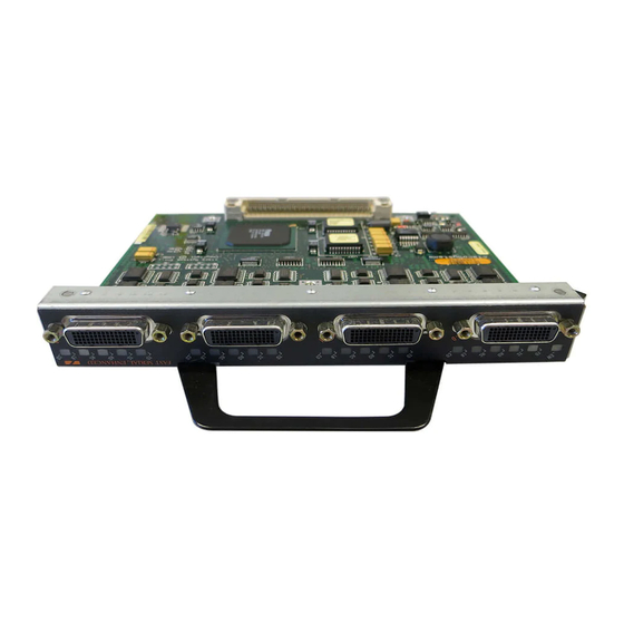
Page 14: Synchronous Serial Overview
Chapter 1 Overview Synchronous Serial Overview Figure 1-2 PA-4T Port Adapter—Faceplate View The PA-4T+ provides four synchronous serial ports, and each port supports full-duplex operations at T1 and E1 speeds. Speed is controlled by three variables: The number of ports in use •... -
Page 15: Serial Interface Specifications
Chapter 1 Overview Serial Interface Specifications The resistance to convert to EIA/TIA-449 was due primarily to the large installed base of DB-25 hardware and to the larger size of the 37-pin EIA/TIA-449 connectors, which limited the number of connections possible (fewer than is possible with the smaller, 25-pin EIA/TIA-232 connector). EIA-530, which supports balanced transmission, provides the increased functionality, speed, and distance of EIA/TIA-449 on the smaller, DB-25 connector used for EIA/TIA-232. -
Page 16: Leds
Chapter 1 Overview LEDs Table 1-1 Standards for Transmission Speed Versus Distance EIA/TIA-232 EIA/TIA-449, X.21, V.35, EIA-530 Distances Distances Rate (bps) Feet Meters Feet Meters 2400 4,100 1,250 4800 2,050 9600 1,025 19200 38400 56000 1544000 (T1) – – Balanced drivers allow EIA/TIA-449 signals to travel greater distances than EIA/TIA-232. The recommended distance limits for EIA/TIA-449 shown in Table 1-1 are also valid for V.35, X.21, and EIA-530. -
Page 17: Cables, Connectors, And Pinouts
Chapter 1 Overview Cables, Connectors, and Pinouts Table 1-2 lists port LED status indications. Table 1-2 PA-4T+ Port LEDs LED Label Color State Function Green Indicates ports are ready. Green DTE—Transmit data out. DCE—Transmit data in. Green DTE—Transmit clock in. DCE—Transmit clock in (TXCE). - Page 18 Chapter 1 Overview Cables, Connectors, and Pinouts Following are the available interface cable options (and product numbers) for the mode and network-end connectors for each cable: EIA/TIA-232: DTE mode with a DB-25 plug (CAB-232MT); DCE mode with a DB-25 receptacle •...
-
Page 19: Eia/Tia-232 Connections
Note The system console and auxiliary ports on the Route Switch Processor (RSP) in the Cisco 7500 series also use EIA/TIA-232 connections; however, the PA-4T+ interfaces support synchronous serial connections, and the console and auxiliary ports only support asynchronous connections. -
Page 20: Eia/Tia-449 Connections
Chapter 1 Overview Cables, Connectors, and Pinouts EIA/TIA-449 Connections The router end of all EIA/TIA-449 adapter cables is a high-density, 60-pin plug. The network end of the adapter cable provides a standard 37-pin D-shell connector, which is commonly used for EIA/TIA-449 connections. -
Page 21: X.21 Connections
Chapter 1 Overview Cables, Connectors, and Pinouts X.21 Connections The router end of all X.21 adapter cables is a high-density, 60-pin plug. The network end of the adapter cable is a standard DB-15 connector. Figure 1-8 shows the connectors at the network end of the X.21 adapter cable. - Page 22 Chapter 1 Overview Cables, Connectors, and Pinouts Table 1-3 EIA/TIA-232 Adapter Cable Signals DTE Cable (CAB-232MT=) DCE Cable (CAB-232FC=) Router End, HD Network End, Router End, HD Network End, 60-Position Plug DB-25 Plug 60-Position Plug DB-25 Receptacle Signal Pin Signal Signal Signal Shield ground...
- Page 23 Chapter 1 Overview Cables, Connectors, and Pinouts Table 1-4 Intermediate Adapter Cable Signals (for Connecting a PA-4T+ to a NEC - NEXTSTAR 1E Model C4969 MD/SAC Unit) (continued) Router (DTE) End, Network (DCE) End, DB-25 Receptacle DB-25 Plug Signal Pin Signal —>...
- Page 24 Chapter 1 Overview Cables, Connectors, and Pinouts Table 1-5 EIA/TIA-449 Adapter Cable Signals DTE Cable (CAB-449MT=) DCE Cable (CAB-449C=) Router End, HD Network End, Router End, HD Network End, 60-Position Plug DB-37 Plug 60-Position Plug DB-37 Receptacle Signal Signal Signal Pin Signal Shield ground Shield ground...
- Page 25 Chapter 1 Overview Cables, Connectors, and Pinouts Table 1-6 EIA-530 DTE Adapter Cable Signals (CAB-530MT=) Router End, HD Network End, 60-Position Plug DB-25 Plug Signal Signal Shield ground Shield ground TxD/RxD+ —> TxD+ TxD/RxD– —> TxD– RxD/TxD+ <— RxD+ RxD/TxD– <—...
- Page 26 Chapter 1 Overview Cables, Connectors, and Pinouts Table 1-7 V.35 Adapter Cable Signals DTE Cable (CAB-V35FT= or CAB-V35MT=) DCE Cable (CAB-V35FC= or CAB-V35MC=) Network End, Router End, HD Network End, Router End, HD 34-Position 60-Position Plug 34-Position Plug 60-Position Plug Receptacle Signal Signal...
-
Page 27: Port Adapter Slot Locations On The Supported Platforms
Catalyst 6000 Family FlexWAN Module Slot Numbering, page 1-16 • Cisco 7100 Series Routers Slot Numbering, page 1-17 Cisco 7200 Series Routers and Cisco 7200 VXR Routers Slot Numbering, page 1-18 • Cisco 7201 Router Slot Numbering, page 1-21 •... -
Page 28: Catalyst Rsm/Vip2 Slot Numbering
Chapter 1 Overview Port Adapter Slot Locations on the Supported Platforms Catalyst RSM/VIP2 Slot Numbering The Catalyst RSM/VIP2 can be installed in any slot in a Catalyst 5000 family switch except the top slots, which contain the supervisor engines. The Catalyst RSM/VIP2 in a Catalyst 5000 family switch does not use interface processor slot numbering;... -
Page 29: Cisco 7100 Series Routers Slot Numbering
Power supply 2 Power supply 1 Cisco 7100 Series Routers Slot Numbering The PA-4T+ can be installed in port adapter slot 3 in Cisco 7120 series routers, and in port adapter slot 4 in Cisco 7140 series routers. Figure 1-12 shows the slot numbering on a Cisco 7120 series router. -
Page 30: Cisco 7200 Series Routers And Cisco 7200 Vxr Routers Slot Numbering
Cisco 7202 routers have two port adapter slots. The slots are numbered from left to right. You can place a port adapter in either of the slots (slot 1 or slot 2). The Cisco 7202 router is not shown. Cisco 7204 routers and Cisco 7204VXR routers have four slots for port adapters, and one slot for an input/output (I/O) controller. - Page 31 Cisco 7206 routers and Cisco 7206VXR routers (including the Cisco 7206 and Cisco 7206VXR as router shelves in a Cisco AS5800 Universal Access Server) have six slots for port adapters, and one slot for an input/output (I/O) controller. The slots are numbered from the lower left to the upper right, beginning with slot 1 and continuing through slot 6.
-
Page 32: Cisco Ubr7200 Series Router Slot Numbering
Port Adapter Slot Locations on the Supported Platforms Cisco uBR7200 Series Router Slot Numbering The Cisco uBR7223 router has one port adapter slot (slot 1). Slot 0 is always reserved for the I/O controller—if present. The Cisco uBR7223 router is not shown. -
Page 33: Cisco 7201 Router Slot Numbering
Port Adapter Slot Locations on the Supported Platforms Cisco 7201 Router Slot Numbering Figure 1-16 shows the front view of a Cisco 7201 router with a port adapter installed. There is only one port adapter slot (slot 1)in a Cisco 7201 router. Figure 1-16... -
Page 34: Cisco 7304 Pci Port Adapter Carrier Card Slot Numbering
Port Adapter Slot Locations on the Supported Platforms Cisco 7304 PCI Port Adapter Carrier Card Slot Numbering The Cisco 7304 PCI Port Adapter Carrier Card installs in Cisco 7304 router module slots 2 through 5. Figure 1-18 shows a Cisco 7304 PCI Port Adapter Carrier Card with a port adapter installed. The Cisco 7304 PCI Port Adapter Carrier Card accepts one single-width port adapter. -
Page 35: Cisco 7401Asr Router Slot Numbering
Port Adapter Slot Locations on the Supported Platforms Cisco 7401ASR Router Slot Numbering Figure 1-20 shows the front view of a Cisco 7401ASR router with a port adapter installed. There is only one port adapter slot (slot 1) in a Cisco 7401ASR router. Figure 1-20... - Page 36 The slots are numbered from bottom to top. You can place a port adapter in any of the VIP interface slots (slot 0 through 2). Slots 3 and 4 are always reserved for RSPs. The Cisco 7010 router is not shown.
-
Page 37: Identifying Interface Addresses
Cisco 7304 PCI Port Adapter Carrier Card Interface Addresses, page 1-28 • Cisco 7401ASR Router Interface Addresses, page 1-28 • Cisco 7000 Series Routers and Cisco 7500 Series Routers VIP Interface Addresses, page 1-29 • Table 1-9 summarizes the interface address formats for the supported platforms. -
Page 38: Catalyst Rsm/Vip2 Interface Addresses
Interface port—0 through 3 Cisco 7304 router Cisco 7401ASR router Port-adapter-slot-number/interface-port-number Port adapter slot—always 1 Interface port—0 through 3 VIP in Cisco 7000 series Interface-processor-slot-number/port-adapter- Interface processor slot—0 3/1/0 routers or Cisco 7500 series slot-number/interface-port-number through 12 (depends on the... -
Page 39: Catalyst 6000 Family Flexwan Module
1 and continuing through slot 2 for the Cisco 7202, slot 4 for the Cisco 7204 and Cisco 7204VXR, and slot 6 for the Cisco 7206 and Cisco 7206VXR. Port adapters can be installed in any available port adapter slot from 1 through 6 (depending on the number of slots in the router). -
Page 40: Cisco Ubr7200 Series Routers Interface Addresses
In the Cisco 7304 router, port adapters are installed in a Cisco 7304 PCI port adapter carrier card, which installs in Cisco 7304 router module slots 2 through 5. The port adapter slot number is the same as the module slot number. See... -
Page 41: Cisco 7000 Series Routers And Cisco 7500 Series Routers Vip Interface Addresses
Although the processor slots in the 7-slot Cisco 7000 router and Cisco 7507router and the 13-slot Cisco 7513 router and Cisco 7576 router are vertically oriented and those in the 5-slot Cisco 7010 router and Cisco 7505 router are horizontally oriented, all Cisco 7000 series routers and Cisco 7500 series routers use the same method for slot and port numbering. - Page 42 Chapter 1 Overview Identifying Interface Addresses PA-4T+ Synchronous Serial Port Adapter Installation and Configuration 1-30 OL-3561-04...
-
Page 43: Required Tools And Equipment
VIP (for installation in Cisco 7000 series or Cisco 7500 series chassis only) • Cisco 7304 PCI Port Adapter Carrier Card (for installation in a Cisco 7304 router) • Serial cables appropriate for the desired port adapter interface types and the desired modes. (See the •... -
Page 44: Software And Hardware Requirements
1. If you are installing only one PA-4T+, you can use the Catalyst RSM/VIP2-15(=); otherwise, we recommend the Catalyst RSM/VIP2-40(=). 2. For PA-4T+ port adapters installed in Cisco 7200 series routers, Cisco IOS Release 11.1(6)CA, or later, is required; however, we recommend Cisco IOS Release 11.1(8)CA or later. -
Page 45: Checking Hardware And Software Compatibility
Access to this tool is limited to users with Cisco.com login accounts. To access Software Advisor, click Log In at Cisco.com and go to Support > Tools and Resources. You can also access the tool by pointing your browser directly to http://www.cisco.com/en/US/support/tsd_most_requested_tools.html. - Page 46 Chapter 2 Preparing for Installation Safety Guidelines IMPORTANT SAFETY INSTRUCTIONS Warning This warning symbol means danger. You are in a situation that could cause bodily injury. Before you work on any equipment, be aware of the hazards involved with electrical circuitry and be familiar with standard practices for preventing accidents.
- Page 47 Chapter 2 Preparing for Installation Safety Guidelines Attention IMPORTANTES INFORMATIONS DE SÉCURITÉ Ce symbole d'avertissement indique un danger. Vous vous trouvez dans une situation pouvant causer des blessures ou des dommages corporels. Avant de travailler sur un équipement, soyez conscient des dangers posés par les circuits électriques et familiarisez-vous avec les procédures couramment utilisées pour éviter les accidents.
- Page 48 Chapter 2 Preparing for Installation Safety Guidelines Advarsel VIKTIGE SIKKERHETSINSTRUKSJONER Dette varselssymbolet betyr fare. Du befinner deg i en situasjon som kan forårsake personskade. Før du utfører arbeid med utstyret, bør du være oppmerksom på farene som er forbundet med elektriske kretssystemer, og du bør være kjent med vanlig praksis for å...
- Page 49 Chapter 2 Preparing for Installation Safety Guidelines PA-4T+ Synchronous Serial Port Adapter Installation and Configuration OL-3561-04...
-
Page 50: Electrical Equipment Guidelines
Chapter 2 Preparing for Installation Safety Guidelines Electrical Equipment Guidelines Follow these basic guidelines when working with any electrical equipment: • Before beginning any procedures requiring access to the chassis interior, locate the emergency power-off switch for the room in which you are working. •... -
Page 51: Telephone Wiring Guidelines
Chapter 2 Preparing for Installation Safety Guidelines Do not perform any action that creates a potential hazard to people or makes the equipment unsafe; • carefully examine your work area for possible hazards such as moist floors, ungrounded power extension cables, and missing safety grounds. Telephone Wiring Guidelines Use the following guidelines when working with any equipment that is connected to telephone wiring or to other network cabling:... -
Page 52: Fcc Class A Compliance
You can determine whether your equipment is causing interference by turning it off. If the interference stops, it was probably caused by the Cisco equipment or one of its peripheral devices. If the equipment causes interference to radio or television reception, try to correct the interference by using one or more of the following measures: Turn the television or radio antenna until the interference stops. -
Page 53: Chapter 3 Removing And Installing Port Adapters
C H A P T E R Removing and Installing Port Adapters This chapter describes how to remove the PA-4T+ port adapter from supported platforms and also how to install a new or replacement port adapter. This chapter contains the following sections: Handling Port Adapters, page 3-1 •... -
Page 54: Online Insertion And Removal
Catalyst RSM/VIP2, Catalyst 6000 family FlexWAN module, Cisco 7304 PCI port adapter carrier card, or VIP on which you want to install a new port adapter, you must first remove the Catalyst RSM/VIP2, Catalyst 6000 family FlexWAN module, Cisco 7304 PCI port adapter carrier card, or VIP from the chassis and then remove the blank port adapter. -
Page 55: Warnings And Cautions
Chapter 3 Removing and Installing Port Adapters Warnings and Cautions Each port adapter has a bus connector that connects it to the router. The connector has a set of tiered pins in three lengths that send specific signals to the system as they make contact with the port adapter. The system assesses the signals it receives and the order in which it receives them to determine if a port adapter is being removed from or introduced to the system. -
Page 56: Port Adapter Removal And Installation
Catalyst 6000 Family FlexWAN Module—Removing and Installing a Port Adapter, page 3-6 • Cisco 7100 Series Routers—Removing and Installing a Port Adapter, page 3-7 • Cisco 7200 Series Routers and Cisco 7200 VXR Routers—Removing and Installing a Port Adapter, page 3-8 • Cisco uBR7200 Series Routers—Removing a Port Adapter, page 3-9 •... -
Page 57: Catalyst Rsm/Vip2-Removing And Installing A Port Adapter
Chapter 3 Removing and Installing Port Adapters Port Adapter Removal and Installation Catalyst RSM/VIP2—Removing and Installing a Port Adapter Note: You must first remove the Catalyst RSM/VIP2 from the chassis before removing a port adapter from the Catalyst RSM/VIP2. Step 1 To remove the port adapter, remove the screw that secures the port adapter (or blank... -
Page 58: Catalyst 6000 Family Flexwan Module-Removing And Installing A Port Adapter
Chapter 3 Removing and Installing Port Adapters Port Adapter Removal and Installation Catalyst 6000 Family FlexWAN Module—Removing and Installing a Port Adapter Note: You must first remove the Catalyst 6000 FlexWAN module from the chassis before removing a port adapter from the Catalyst 6000 FlexWAN module. -
Page 59: Cisco 7100 Series Routers-Removing And Installing A Port Adapter
Chapter 3 Removing and Installing Port Adapters Port Adapter Removal and Installation Cisco 7100 Series Routers—Removing and Installing a Port Adapter Step 1 To remove the port adapter, use a number 2 Phillips screwdriver to loosen the screws on the locking tab. Then slide the tab down to the unlocked position. -
Page 60: Cisco 7200 Series Routers And Cisco 7200 Vxr Routers-Removing And Installing A Port Adapter
Chapter 3 Removing and Installing Port Adapters Port Adapter Removal and Installation Cisco 7200 Series Routers and Cisco 7200 VXR Routers—Removing and Installing a Port Adapter Step 1 Port adapter lever To remove the port adapter, place (locked position) the port adapter lever in the unlocked position. -
Page 61: Cisco Ubr7200 Series Routers-Removing A Port Adapter
Chapter 3 Removing and Installing Port Adapters Port Adapter Removal and Installation Cisco uBR7200 Series Routers—Removing a Port Adapter Step 1 Port adapters To remove the port adapter, unlock the port adapter retaining mechanism. The port Port adapter lever adapter lever remains in the (locked position) unlocked position. -
Page 62: Cisco Ubr7200 Series Routers-Installing A Port Adapter
Chapter 3 Removing and Installing Port Adapters Port Adapter Removal and Installation Cisco uBR7200 Series Routers—Installing a Port Adapter Step 1 Metal carrier To insert the port adapter, carefully align the port adapter carrier between the upper and the lower edges of the port adapter slot. -
Page 63: Cisco 7201 Router-Removing And Installing A Port Adapter
Chapter 3 Removing and Installing Port Adapters Port Adapter Removal and Installation Cisco 7201 Router—Removing and Installing a Port Adapter Step 1 Use an ESD wrist strap to ground yourself to the router. Step 2 To remove the port adapter, place the port adapter lever in the unlocked position. The port adapter lever remains in the unlocked position. -
Page 64: Cisco 7301 Router-Removing And Installing A Port Adapter
Chapter 3 Removing and Installing Port Adapters Port Adapter Removal and Installation Cisco 7301 Router—Removing and Installing a Port Adapter Step 1 Use an ESD wrist strap to ground yourself to the router. Step 2 To remove a port adapter, use a Phillips screwdriver to turn the screw holding the port adapter latch. The screw should be loose enough to allow the latch to rotate to an unlocked position. -
Page 65: Cisco 7304 Pci Port Adapter Carrier Card-Removing And Installing A Port Adapter
To remove and install a port adapter in a Cisco 7304 PCI Port Adapter Carrier Card, refer to Figure 3-2 and do the following: If the Cisco 7304 PCI Port Adapter Carrier Card is still in the router, you must remove the Cisco 7304 Step 1 PCI Port Adapter Carrier Card before removing a port adapter. - Page 66 Removing and Installing Port Adapters Port Adapter Removal and Installation Figure 3-2 illustrates how to remove and install a port adapter in a Cisco 7304 PCI Port Adapter Carrier Card. Figure 3-2 Cisco 7304 PCI Port Adapter Carrier Card—Port Adapter Removal and Installation...
-
Page 67: Cisco 7401Asr Router-Removing And Installing A Port Adapter
Step 4 To insert the port adapter, locate the port adapter slot guides inside the Cisco 7401ASR router. They are near the top, and are recessed about 1/2 inch. (See B.) Caution The port adapter must slide into the slot guides under the chassis lid. -
Page 68: Vip-Removing And Installing A Port Adapter
Chapter 3 Removing and Installing Port Adapters Port Adapter Removal and Installation VIP—Removing and Installing a Port Adapter Note: You must first remove the VIP from the chassis before removing a port adapter from the VIP. Step 1 To remove the port adapter, remove the screw that secures the port adapter (or blank port adapter). -
Page 69: Chapter 4 Attaching The Pa-4T+ Interface Cables
C H A P T E R Attaching the PA-4T+ Interface Cables To continue your PA-4T+ port adapter installation, you must install the port adapter cables and configure the PA-4T+ interfaces. The instructions that follow apply to all supported platforms. This chapter contains the following sections: Connecting PA-4T+ Port Adapter Interface Cables, page 4-1 •... -
Page 70: Determining The Port Mode
Universal (cable unattached) rather than either a DTE or DCE interface. Following is an example of the show controllers command for Cisco 7100 series routers, Cisco 7200 series routers, Cisco uBR7200 series routers, Cisco 7201 routers, Cisco 7301 routers, or... - Page 71 EXEC.) Add additional configuration commands, as needed, before you exit from configuration mode (before you press Ctrl-Z or enter end). For the Cisco 7100 series routers, Cisco 7200 series routers, Cisco uBR7200 series routers, Cisco 7201 router, Cisco 7301 router, or Cisco 7401ASR router use the following commands: Router>...
- Page 72 Enter configuration mode again, bring the port back up, and save the running configuration to NVRAM. Step 4 For the Cisco 7100 series routers, Cisco 7200 series routers, Cisco uBR7200 series router,s Cisco 7201 router, Cisco 7301 router, or Cisco 7401ASR router use the following commands: Router# configure terminal Enter configuration commands, one per line.
- Page 73 Chapter 4 Attaching the PA-4T+ Interface Cables Determining the Port Mode For a Catalyst 6000 family FlexWAN module, use the following commands: Router# configure terminal Enter configuration commands, one per line. End with CNTL/Z. Router(config)# interface serial 3/0/0 Router(config-if)# no shutdown Ctrl-Z Router# Router# copy running-config startup-config...
- Page 74 Chapter 4 Attaching the PA-4T+ Interface Cables Determining the Port Mode PA-4T+ Synchronous Serial Port Adapter Installation and Configuration OL-3561-04...
-
Page 75: Chapter 5 Configuring The Pa-4T+ Interfaces
This chapter contains the following sections: Using the EXEC Command Interpreter, page 5-1 • Configuring the Interfaces, page 5-2 • Configuring Half-Duplex and Binary Synchronous Communications in Cisco 7200 Series Routers, • page 5-16 Checking the Configuration, page 5-18 •... -
Page 76: Configuring The Interfaces
Chapter 5 Configuring the PA-4T+ Interfaces Configuring the Interfaces Configuring the Interfaces After you verify that the new PA-4T+ is installed correctly (the enabled LED goes on), use the privileged-level configure command to configure the new interfaces. Be prepared with the information you will need, such as the following: Protocols you plan to route on each new interface •... - Page 77 Router(config-if)# interface serial 4/1 Router(config-if)# shutdown shutdown Ctrl-Z Router# Cisco 7200 series routers and interface, followed by the type The example is for interface 0 and interface 1 on a Cisco 7200 VXR routers (serial) and slot/port port adapter in port adapter slot 6.
- Page 78 Carrier Card in a Cisco 7304 (serial) and slot/port port adapter in a Cisco 7304 PCI Port Adapter router (module-slot-number/ Carrier Card in module slot 3 of a Cisco 7304 router. interface-port-number) Router(config-if)# interface serial 3/0 Router(config-if)# shutdown shutdown Router(config-if)# interface serial 3/1...
- Page 79 Router(config-if)# interface serial 1/1 Router(config-if)# shutdown shutdown Ctrl-Z Router# VIP in Cisco 7000 series routers interface, followed by the type The example is for interface 1 and interface 0 on a or Cisco 7500 series routers (serial) and slot/port adapter/port...
- Page 80 Serial 4/0 is administratively down, line protocol is down [Additional display text omitted from this example] Cisco 7200 series routers and show interfaces serial, followed The example is for interface 0 on a Cisco 7200 VXR routers by slot/port port adapter in port adapter slot 6.
- Page 81 Card in a Cisco 7304 router by slot/port (module-slot-number/ adapter in a Cisco 7304 PCI Port Adapter interface-port-number) Carrier Card in module slot 3 of a Cisco 7304 router. Router# show interfaces serial 3/0 Serial 3/0 is administratively down, line protocol is down...
-
Page 82: Performing A Basic Configuration
Serial 1/0 is administratively down, line protocol is down [Additional display text omitted from this example] VIP in Cisco 7000 series routers or show interfaces serial, followed The example is for interface 0 on a port Cisco 7500 series routers... - Page 83 4. (port-adapter-slot-number/ Router(config)# interface serial 4/0 interface-port-number) Router(config-if)# Cisco 7200 series routers and interface serial, followed by The example is for interface 0 of a Cisco 7200 VXR routers slot/port port adapter in port adapter slot 6.
- Page 84 The example is for interface 0 on a port Card in a Cisco 7304 router slot/port (module-slot-number/ adapter in a Cisco 7304 PCI Port Adapter interface-port-number) Carrier Card in module slot 3 of a Cisco 7304 router. Router(config)# interface serial 3/0 Router(config-if)# Cisco 7401ASR router...
-
Page 85: Configuring Timing (Clock) Signals
Chapter 5 Configuring the PA-4T+ Interfaces Configuring the Interfaces Write the new configuration to NVRAM as follows: Step 9 Router# copy running-config startup-config [OK] Router# This completes the procedure for creating a basic configuration. Configuring Timing (Clock) Signals All PA-4T+ interfaces support both DTE and DCE mode, depending on the mode of the interface cable attached to the port. -
Page 86: Setting The Clock Rate
Chapter 5 Configuring the PA-4T+ Interfaces Configuring the Interfaces Table 5-4 Clock Rate Configuration Commands Purpose Command Example Additional Information Set standard clock rate. clock rate The example is for a serial interface with a “Setting the Clock Rate” standard clock rate of 72 kbps. Router(config)# interface serial 3/0 Router(config-if)# clock rate 7200 Set nonstandard clock... -
Page 87: Inverting The Clock Signal
EXEC command interpreter prompt. Then write the new configuration to NVRAM using the copy running-config startup-config command. Cisco IOS Release 11.2(7a)P or later, or 11.1(10)CA or later loaded on your Cisco 7200 series router, Note Cisco 7000 series router, or Cisco 7500 series router with a VIP2-40(=) support nonstandard clock rates (any value from 1200 to 8000000) on PA-4T+ interfaces. -
Page 88: Inverting The Data Signal
Chapter 5 Configuring the PA-4T+ Interfaces Configuring the Interfaces Inverting the Data Signal If the interface on the PA-4T+ synchronous serial port adapter is used to drive a dedicated T1 line that does not have B8ZS encoding (a method to avoid 15 zeros), the data stream must be inverted (both TxD and RxD) either in the connecting CSU/DSU or the interface. -
Page 89: Configuring Cyclic Redundancy Checks
NVRAM using the copy running-config startup-config command. For complete command descriptions and instructions, refer to the Configuration Fundamentals Configuration Guide on Cisco.com. Configuring Cyclic Redundancy Checks Cyclic redundancy check (CRC) is an error-checking technique that uses a calculated numeric value to detect errors in transmitted data. -
Page 90: Configuring Half-Duplex And Binary Synchronous Communications In Cisco 7200 Series Routers
For command descriptions, refer to the Configuration Fundamentals Configuration Guide on Cisco.com. Note If you are configuring a PA-4T+ in a Cisco 7200 series router and you want to configure the interface for half-duplex or Bisync operation, proceed to the next section, “Configuring Half-Duplex and Binary... - Page 91 Chapter 5 Configuring the PA-4T+ Interfaces Configuring Half-Duplex and Binary Synchronous Communications in Cisco 7200 Series Routers Specify the interface to configure for controlled-carrier mode using the interface serial subcommand Step 2 (followed by the interface address of the interface) and then enter the half-duplex controlled-carrier subcommand.
-
Page 92: Checking The Configuration
Cisco.com. Note To configure PA-4T+ interfaces for Binary Synchronous (Bisync) operation in Cisco 7200 series series routers, refer to the “Block Serial Tunneling (BSTUN)” section of the “Configuring Serial Tunnel (STUN) and Block Serial Tunnel (BSTUN)” chapter of the Bridging and IBM Networking Configuration Guide on Cisco.com. - Page 93 (for example, serial) on a Cisco 7200 series router, Cisco 7200 VXR routers, Cisco 7201 router, Cisco 7301 router, or Cisco 7401ASR router show interfaces type 1/interface-port- Displays status information Router# show interfaces serial 1/1...
-
Page 94: Using The Show Version Or Show Hardware Commands
Using the show version or show hardware Commands Display the configuration of the system hardware, the number of each interface type installed, the Cisco IOS software version, the names and sources of configuration files, and the boot images, using the show version (or show hardware) command. - Page 95 Cisco 7401ASR Router—Example Output of the show version Command, page 5-24 • • VIP in Cisco 7000 Series Routers and Cisco 7500 Series Routers—Example Output of the show version Command, page 5-24 Catalyst RSM/VIP2 in Catalyst 5000 Family Switches—Example Output of the show version Command...
- Page 96 Cisco 7100 Series Routers, Cisco 7200 Series Routers, Cisco 7200 VXR Routers, and Cisco uBR7200 Series Routers—Example Output of the show version Command Following is an example of the show version command from a Cisco 7200 series router with a PA-4T+ installed:...
- Page 97 4096K bytes of Flash internal SIMM (Sector size 256K). Configuration register is 0x0 Cisco 7201 Router—Example Output of the show version Command Following is an example of the show version command from a Cisco 7201 router: Router# show version Cisco IOS Software, 7200 Software (C7200P-ADVENTERPRISEK9-M), Version 12.4(biffDEV.061001), INTERIM SOFTWARE Copyright (c) 1986-2006 by Cisco Systems, Inc.
- Page 98 Configuration register is 0x0 VIP in Cisco 7000 Series Routers and Cisco 7500 Series Routers—Example Output of the show version Command Following is an example of the show version command from a Cisco 7500 series router with a PA-4T+ installed:...
-
Page 99: Using The Show Diag Command
Display the types of port adapters installed in your system (and specific information about each) using the show diag slot command, where slot is the port adapter slot in a Catalyst 5000 family switch, a Cisco 7100 series router, Cisco 7200 series router, Cisco 7200 VXR router, Cisco uBR7200 series, Cisco 7201... - Page 100 Serial number: 00000000 Part number: 00-0000-00 Cisco 7100 Series Routers, Cisco 7200 Series Routers, Cisco 7200 VXR Routers, and Cisco uBR7200 Series Routers—Example Output of the show diag Command Following is an example of the show diag command that shows a PA-4T+ installed in port adapter slot 1...
- Page 101 0x30: FF FF FF FF FF FF FF FF FF FF FF FF FF FF FF FF Cisco 7201 Router—Example Output of the show diag Command Following is an example of the show diag command from a Cisco 7201 router: Router# show diag 1...
-
Page 102: Using The Show Interfaces Command
Configuring the PA-4T+ Interfaces Checking the Configuration VIP in Cisco 7000 Series Routers and Cisco 7500 Series Routers—Example Output of the show diag Command Following is an example of the show diag command that shows a PA-4T+ installed in port adapter slot 0... - Page 103 • Cisco 7401ASR Router—Example Output of the show interfaces Command, page 5-32 • VIP in Cisco 7000 Series Routers or Cisco 7500 Series Routers—Example Output of the show • interfaces Command, page 5-32 Catalyst RSM/VIP2 in Catalyst 5000 Family Switches—Example Output of the show interfaces Command Following are examples of the show interfaces serial command for a Catalyst 5000 Family switch.
- Page 104 0 carrier transitions RTS down, CTS down, DTR down, DCD down, DSR down Cisco 7100 Series Routers, Cisco 7200 Series Routers, Cisco 7200 VXR Routers, and Cisco uBR7200 Series Routers—Example Output of the show interfaces Command Following are examples of the show interfaces serial command from a Cisco 7100 series routers. In these examples, the eight serial interfaces (0 to 7) are on a port adapter in port adapter slot 1;...
- Page 105 RTS=up CTS=up Cisco 7201 Router—Example Output of the show interfaces Command Following is an example of the show interfaces command from a Cisco 7201 router: Router# show interfaces GigabitEthernet0/0 is up, line protocol is up Hardware is MV64460 Internal MAC, address is 0019.56c5.2adb (bia 0019.56c5.2adb)
- Page 106 RTS=up CTS=up VIP in Cisco 7000 Series Routers or Cisco 7500 Series Routers—Example Output of the show interfaces Command Following are example s of the show interfaces serial command from a VIP. In these examples, the eight serial interfaces (0 to 7) are on a port adapter in port adapter slot 1 of a VIP in interface processor slot 3;...
-
Page 107: Using The Ping Command To Verify Network Connectivity
Chapter 5 Configuring the PA-4T+ Interfaces Checking the Configuration Router# show interfaces serial 3/1/2 Serial3/1/2 is up, line protocol is up Hardware is cyBus Serial Internet address is 10.0.0.2 MTU 1500 bytes, BW 1544 Kbit, DLY 20000 usec, rely 255/255, load 1/255 Encapsulation HDLC, loopback not set, keepalive not set [Additional display text for remaining interfaces omitted] Following is an example of the show interfaces serial command, which shows all of the information... -
Page 108: Using Loopback Commands
Chapter 5 Configuring the PA-4T+ Interfaces Checking the Configuration Using loopback Commands The loopback test allows you to detect and isolate equipment malfunctions by testing the connection between the PA-4T+ interface and a remote device such as modems or CSU/DSUs. The loopback subcommand sends a series of packets out to and through the device (or cable), and back to the PA-4T+ interface.