
Related Manuals for Samsung MCU-R4NEK0N


Summary of Contents for Samsung MCU-R4NEK0N
- Page 1 Air conditioner Installation manual HR Changer MCU-R4NEK0N • Thank you for purchasing this Samsung air conditioner. • Before operating this unit, please read this user manual carefully and retain it for future reference.
-
Page 2: Table Of Contents
Contents Safety Information Safety Information Preparation Preparing the installation Accessories Selecting the refrigerant pipe for installation HR Changer, MCU, Indoor and outdoor unit compatible table Installation Space requirements Installing the unit Method and cautions on brazing the pipe Refrigerant piping works Method and cautions on refrigerant pipe insulation Installing the circuit breaker and wires Wiring works... -
Page 3: Safety Information
Safety Information The safety information and precautions below must be kept for the safety of users and installers. Before installing an air conditioner, please read this manual thoroughly to ensure that you know how to • DVM S air conditioner uses R-410A refrigerant. - When using R-410A, moisture or foreign substances may affect the capacity and reliability of the product. -
Page 4: Safety Information
Safety Information Before welding the unit, you must remove all the hazardous materials around the unit that may cause an refrigerant. - If you weld the unit when there is refrigerant inside, the increased pressure of refrigerant may explode or break the leaking spot so that causes serious injuries. When the electric wire is damaged, you must exchange it by the manufacturer or its service agent, or a When turning on the power, make sure to connect the power supply to the circuit breaker designated for indoor units. - Page 5 FOR INSTALLATION CAUTION Make sure to earth. Make sure that the condensed water from the drain hose runs out properly based on this installation manual and insulate the drain pipe so that frost does not generate. Install the power cable and communication cable of HR Changer at least 1m away from the electric appliances and at least 2m away from the lightning rod.
- Page 6 Safety Information pourront pas fonctionner normalement.) WARNING CAUTION MONTAGE AVERTISSEMENT L'installation doit être faite par l'installateur ou son agent de service. Installez l'appareil conformément au manuel d'installation. Lors de l'installation de l'appareil dans un espace restreint, prenez les mesures appropriées pour éviter que Installez l'appareil en toute sécurité...
- Page 7 dans le tuyau. nettoyage de l'appareil. Lorsque vous mettez l'appareil sous tension, veillez à effectuer le raccordement à un disjoncteur conçu pour les unités intérieures. (ELCB, ELB, MCCB) MONTAGE AVERTISSEMENT ne puisse provoquer une traction sur le bornier. nominale. Veillez à ce que l'alimentation électrique de l'unité intérieure ne soit ni supérieure ni inférieure à la tension nominale.
- Page 8 Safety Information MONTAGE MISE EN GARDE Veillez à effectuer une mise à la terre conforme. Veillez à ce que les condensats s'évacuent correctement par le tuyau de vidange conformément aux formation de givre. Installez la MCU loin de tout dispositif d'éclairage utilisant un ballast. N'installez pas l'appareil dans les lieux suivants.
-
Page 9: Preparing The Installation
Preparing the installation Accessories Please check if items below are included in installation accessories. Insulation Insulation Installation Pattern Name Cable tie Tube Cap (for pipe) (for base) manual sheet Shape Please purchase Y-connector separately. (Not included) Y-connector Name [ Ø 9.52 mm (3/8"): DB96-23143A ], [ Ø 15.88 mm (5/8"): DB96-23144A ] Shape Selecting the refrigerant pipe for installation below in selecting the installation pipe. -
Page 10: Hr Changer, Mcu, Indoor And Outdoor Unit Compatible Table
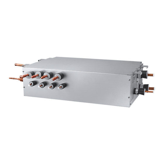
Preparing the installation HR Changer, MCU, Indoor and outdoor unit compatible table Outdoor Unit HR Changer Sub MCU Indoor Unit AM****N**** AM****XMD*R • HR Changer can be installed in series or in parallel. HR Changer must be installed after the outdoor unit. Cooling only indoor units must be installed bhind the HR Changer. - Page 11 Gas pipe connected to the indoor units < Side view of HR Changer > Connect to the Sub MCU < HR Changer (MCU-R4NEK0N) > English...
-
Page 12: Space Requirements
Space requirements Space requirements 1. Since refrigerant noise can be generated during the HR Changer operation, do not install the unit on the ceiling of may disturb people in that area and cause inconvenience. <Spaces with developed ceiling> HR Changer HR Changer Bulkhead Hallway... - Page 13 noise of the HR Changer may get louder during winter time. Therefore, above installation conditions must be complied. 8. Select the place where HR Changer supporting structure can support the weight of the indoor unit and have strong vibration resistance without any slope. (If the structure is not strong enough, HR Changer may fall down and break, which can cause injury to your body.) Ceiling concrete or more...
-
Page 14: Installing The Unit
Installing the unit Installing the unit Unit HR Changer Model name The exterior The number of branches The maximum number of the connectable indoor unit per branch The maximum capacity of the connectable indoor unit per branch The maximum capacity of connectable indoor units per branch (Using Y-Joint) The maximum capacity of connectable indoor units 22.4... - Page 15 2. Installing the indoor unis HR Changer HR Changer HR Changer < Serial installation > < Parallel installation > In case of using Y-connector, it is only connectable for port combination as the followings; Set Dip Switch option for using Y-connector MCU address swich DIP switch...
- Page 16 Installing the unit 1) Place the pattern sheet on the ceiling at the spot where you want to install the indoor unit. • Since the diagram is made of paper, it may shrink or stretch slightly holes maintain the correct dimensions between the markings. Concrete 2) Insert bolt anchors, use existing ceiling supports or construct a Insert...
- Page 17 Protect with wet towel when welding Pipe connection to Pipe connection from the outdoor unit 70 mm the another MCU High pressure gas pipe connection (welding) Pipe connection the outdoor unit Gas pipe (welding) When installing HR Changer , use the pattern sheet for installation that is provided with the product. •...
-
Page 18: Method And Cautions On Brazing The Pipe
Installing the unit Method and cautions on brazing the pipe Keeping refrigerant pipe clean and dry clean, dry and sealed during installation. Exposure place Exposure time Sealing type Pipe pinch Shorter than one month Taping Inside exposure Taping Brazing the pipe The use of Nitrogen gas Brazing 1. -
Page 19: Refrigerant Piping Works
Refrigerant piping works Method and cautions on refrigerant pipe insulation Make sure to check for gas leakage before completing the installation (hose and pipe insulation) and insulate hoses and pipes when there is no sign of leakage. No gap Butadien Rubber separately around each refrigerant pipe. •... - Page 20 Refrigerant piping works Insulation kit and HR Changer Insulation pipes should not be pressed. Gas pipe thicker insulator. space. thicker insulation. Gas pipe • Install the insulation not to get wider and use the adhesives on the connection part of it to prevent moisture from entering.
-
Page 21: Installing The Circuit Breaker And Wires
Installing the circuit breaker and wires Power supply MCCB Power cable Earth cable Communication cable Max : 242V 0.1 sec Installing the wire Case 1 Case 2 HR Changer HR Changer Indoor Indoor Indoor Indoor Indoor MCCB MCCB Unit Unit Unit Changer Unit... - Page 22 Refrigerant piping works Hole for communication Hole for HR Changer main power supply Choose the compressed socket based on the cross-section of the connecting wire. Silver solder Nominal dimensions for cable [mm2 (inch2)] 4 (0.006) Nominal dimensions for screw [mm (inch)] Standard dimension [mm (inch)] Allowance [mm (inch)] ±0.2 (0.007)
-
Page 23: Wiring Works
Wiring works Setting HR Changer address and port Process 1. HR Changer Set HR Changer address by rotary switch. address setting set bottom rotary switch to 1 HR Changer HR Changer Address Address Default Setting HR Changer adress to 21 2. - Page 24 Wiring works 4. HR Changer address and Manual setting : port setting 1. Wireless remote controller for indoor unit 2) Assign an indoor unit HR Changer port address by wireless remote controller Setting Main 100-digit of indoor 10-digit of indoor The unit digit of Mode address...
- Page 25 4. HR Changer 2. Wireled remote controller address and 1) Press the Delete and Set buttons at the same time for more than three seconds. Then you port setting for indoor unit 2) Assign an indoor unit HR Changer port address with main menu 4, sub menu 7 (HR Changer Setting value Data bit Main...
- Page 26 Wiring works • The Direct-connected indoor unit without HR Changer like below picture, be sure to set their Note) the direct connected indoor unit without HR Changer 1. Check whether power is supplied or not. - When the indoor unit is not plugged in, there should be additional power supply in the indoor unit. 2.
- Page 27 Option No. : 05XXXX-1XXXXX-2XXXXX-3XXXXX (When setting (When setting Standard heating Standard Standard cooling Cooling only unit setting for mode change Remote Controller Display Indication Details Indication Details Indication Details Indication Details Indication Details Indication Details option Use Auto Change Indication and Details Cooling only unit setting...
- Page 28 Wiring works Display HR Changer status Display segment Display Contents Remarks (Pushed time) Blank HR Changer address 0 Blank HR Changer address 1 HR Changer address Blank HR Changer address 2 Blank HR Changer address 11 Blank Subcooler-in sensor temperature Blank Subcooler-out sensor temperature Blank...
- Page 29 Display segment Display Contents Remarks (Pushed time) Indoor unit main address for matching with port A Indoor unit main address of port A : 0 Indoor unit main address for matching with port B Indoor unit main address for matching with port C Indoor unit main address of port C : 6 Indoor unit main address for matching with port D operate following indoor operation mode.
-
Page 30: Commisioning
Commisioning to complete it. Item Check 1. If the gas leaking test has been completed or not. 4. If the R-410A refrigerant has been charged or not. If the subsidiary unit for R-410A has been used or not. 6. If the HR Changer frame has been installed upside-down or not. If the wire earthing work has been done or not. - Page 31 Memo English...