Table of Contents
Advertisement
Quick Links
Advertisement
Table of Contents
Troubleshooting

Related Manuals for Honeywell BW GasAlertMicro 5


Summary of Contents for Honeywell BW GasAlertMicro 5
- Page 1 1, 2, 3, 4, 5 Gas Detector User Manual...
- Page 2 Limited Warranty and Limitation Liability BW Technologies LP (BW) warrants the product to be free from defects in material and workmanship under normal use and service for a period of two years, beginning on the date of shipment to the buyer. This warranty extends only to the sale of new and unused products to the original buyer. BW’s warranty obligation is limited, at BW’s option, to refund of the purchase price, repair or replacement of a defective product that is returned to a BW authorized service center within the warranty period.
-
Page 3: Table Of Contents
Table of Contents Title Page Introduction ..................................1 Gases Monitored ................................2 Safety Information - Read First............................2 aCautions ..................................3 Sensor Poisons and Contaminants ..........................6 Getting Started ..................................8 Parts of the GasAlertMicro 5/PID/IR ..........................9 Screen Elements ................................10 Buttons .................................... -
Page 4: Title Page
GasAlertMicro 5/PID/IR User Manual Title Page User Options Menu ................................21 Exit User Options Menu ..............................22 Options Menu................................. 22 Backlight ................................... 23 Confidence Beep ..............................23 Due-Lock .................................. 23 Latched Alarms ................................. 24 Passcode Protect..............................24 Safe Display................................25 Sensor Configuration .............................. - Page 5 GasAlertMicro 5/PID/IR User Manual Title Page Sleep Mode................................39 Alarms ....................................40 Gas Exposures Computed ............................. 43 Viewing Gas Exposures ..............................43 Clearing Gas Exposures ..............................44 Gas Alarm Setpoints ..............................44 Viewing the Alarm Setpoints ............................44 Resetting Gas Alarm Setpoints ............................45 Stopping a Gas Alarm ..............................
- Page 6 GasAlertMicro 5/PID/IR User Manual Title Page Setting the Calibration Due Date ..........................57 Alarm Setpoints ................................ 58 Setting the Remaining Alarm Setpoints ........................60 Finish Calibration ..............................60 Verification ................................61 Unsuccessful Span ..............................61 Pump ....................................64 ....................................... 64 Identifying the Pump ..............................
- Page 7 GasAlertMicro 5/PID/IR User Manual Title Page View Datalog Files in Spreadsheets ..........................77 Example of a Datalog Spreadsheet .......................... 78 Maintenance ..................................81 Battery Cautions ................................81 Charging the Battery ..............................81 Replacing the Alkaline Batteries ............................ 82 Replacing the Lithium Battery Pack ..........................83 Replacing a Sensor or Sensor Filter ..........................
- Page 8 List of Figures Figure Title Page Parts of the GasAlertMicro 5/PID/IR........................9 Screen Elements ..............................10 Applying Gas to the Sensors ..........................50 Single Gas Calibration Cap ..........................51 Removing the Single Gas Calibration Cap ......................51 Installing the Pump Module ..........................66 Replacing the Pump Filter (Generation 2 Pump)....................
- Page 9 List of Tables Table Title Page Gases Monitored ..............................2 Sensor Poisons and Contaminants ........................6 International Symbols ............................7 Parts of the GasAlertMicro 5/PID/IR........................9 Screen Elements ..............................10 Button .................................. 11 Alarms ................................. 40 Computed Gas Exposures ..........................43 Gas Alarm Setpoints ............................
- Page 10 GasAlertMicro 5/PID/IR User Manual Replacement Parts and Accessories ........................95 PID Corrections Factor (CF) Library........................102 GlobalTestSupply www. .com Find Quality Products Online at: sales@GlobalTestSupply.com...
-
Page 11: Introduction
GasAlertMicro 5/PID/IR Introduction GasAlertMicro 5/PID/IR Introduction a Warning ISO 9001 To ensure personal safety, read the Safety Information - Read First and Cautions before using the detector. The GasAlertMicro 5, GasAlertMicro 5 PID, and GasAlertMicro 5 IR gas detectors (“the detector”) warn of hazardous gas at levels above user-defined alarm setpoints. -
Page 12: Gases Monitored
GasAlertMicro 5/PID/IR User Manual Gases Monitored CAUTION: FOR SAFETY REASONS, THIS EQUIPMENT MUST BE OPERATED AND SERVICED BY QUALIFIED PERSONNEL ONLY. The following table lists the gases that are monitored by the detector. READ AND UNDERSTAND THIS USER MANUAL COMPLETELY Table 1. -
Page 13: Acautions
Although certain organic vapors (such as leaded gasoline • If the detector is damaged or parts are missing, contact BW and halogenated hydrocarbons) may temporarily inhibit Technologies by Honeywell immediately. sensor performance, in most cases, the sensor will recover after calibration. - Page 14 • Read and adhere to all instructions in the charger user in the user manual and/or that part is listed as a manual. Failure to do so can result in fire, electrical shock, replacement part. Use only BW Technologies by Honeywell personal injury, and/or property damage. Replacement Parts and Accessories.
- Page 15 GasAlertMicro 5/PID/IR aCautions • Do not use any other lithium batteries with the GasAlertMicro 5/PID/IR detectors. Use of any other cell can cause fire and/or explosion. To order and replace the M5- BAT08 battery, refer to Replacement Parts and Accessories. •...
-
Page 16: Sensor Poisons And Contaminants
Aerosols Lubricants a Caution Brake cleaners Silicone cleaners Bug repellents and protectants and sprays Use only the following BW Technologies by Honeywell recommended products and procedures: Lubricants Silicone based Lubricants adhesives, seal- • Use water based cleaners. ants, and gels •... -
Page 17: International Symbols
GasAlertMicro 5/PID/IR Sensor Poisons and Contaminants Table 3. International Symbols Symbol Description Approved to both U.S. and Canadian Standards by CSA International European Explosives Protection Conforms to European Union Directives ATEX Conforms to European ATEX Directives International Electrotechnical Commission Scheme for Certification to Standards for Electrical Equipment for IECEx Explosive Atmospheres EAC Ex... -
Page 18: Getting Started
GasAlertMicro 5/PID/IR User Manual Getting Started The detector is shipped with the sensors, and battery packs installed. To replace sensors, the pump, or the battery pack, refer to Replacement The list below provides the standard items included with the detector. Parts and Accessories. -
Page 19: Parts Of The Gasalertmicro 5/Pid/Ir
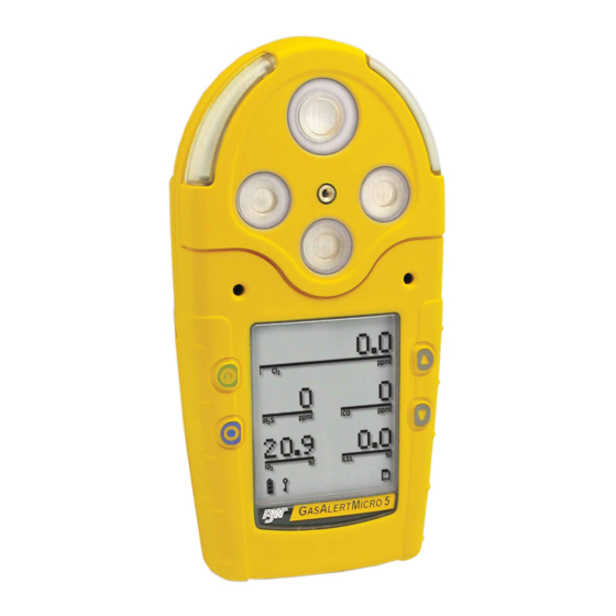
GasAlertMicro 5/PID/IR Parts of the GasAlertMicro 5/PID/IR Parts of the GasAlertMicro 5/PID/IR Table 4. Parts of the GasAlertMicro 5/PID/IR Item Description Liquid crystal display (LCD) Buttons Audible alarms Toxic 2 sensor Toxic 1/PID sensor (GasAlertMicro 5 PID) Toxic 1/IR (CO ) sensor (GasAlertMicro 5 IR) Visual alarm indicators (LEDs) LEL sensor... -
Page 20: Screen Elements
GasAlertMicro 5/PID/IR User Manual Screen Elements Table 5. Screen Elements Item Description Alarm condition Automatically span sensor Gas cylinder Gas type Battery life indicator Passcode lock Data transmission Clock Stealth mode Pump indicator (optional) MMC indicator (optional) Alarm condition (low, high, TWA, STEL, or multi alarm) or view TWA, STEL and peak (MAX) gas expo- Figure 2. -
Page 21: Buttons
GasAlertMicro 5/PID/IR Buttons Buttons Table 6. Button Button Description • To activate the detector press A. • To deactivate the detector, press and hold A until the countdown is complete. • To increment the displayed value or scroll up, press G. •... -
Page 22: Activating The Detector
GasAlertMicro 5/PID/IR User Manual Activating the Detector Battery Test If using the pump module, attach it and the pump accessories prior to The detector performs a battery test during startup. If the battery has activating the detector. insufficient power to operate, the following screen displays before deactivating. -
Page 23: Datalogging (Optional)
GasAlertMicro 5/PID/IR Activating the Detector 2. The version and serial number of the detector displays. Note If there is a problem with the MMC/SD card, Datalogger disabled displays. The detector then automatically continues with the self-test. If the card requires formatting, the following screen displays as the card is automatically formatted. - Page 24 GasAlertMicro 5/PID/IR User Manual Self-test Successful: If successful, the following screen displays. 7. The TWA, STEL, low, and high alarm setpoints then display in the following order (left to right). STEL Self-test Unsuccessful: If a sensor fails the self-test, a warning displays indicating which sensor(s) has failed.
-
Page 25: Pump Test
BW Technologies by Honeywell immediately. • The detector prompts for a pump test during start-up • The pump module passes the pump test at start-up when the pump inlet or sample chain inlet is blocked •... - Page 26 GasAlertMicro 5/PID/IR User Manual If the pump inlet is not blocked within 10 seconds or the pump 9. Unless disabled in user options, the oxygen (O ) sensor is cali- test fails, the following screens display. brated automatically. If C is not pressed or the pump is not removed within If the calibration is successful, the detector beeps twice.
-
Page 27: Due-Lock Enabled
GasAlertMicro 5/PID/IR Activating the Detector If any sensor is over due for calibration, the LCD displays the If no passcode is entered, or it is entered incorrectly, the follow- name of the sensor and the number of days past due. ing screen displays. -
Page 28: Bump Daily Enabled
GasAlertMicro 5/PID/IR User Manual Successful Bump Test: If the bump test passes, the following screens display. Bump Daily Enabled a Caution The detector waits for the sensor(s) to clear (30 seconds) and then BW recommends that a bump test to all sensors be enters normal operation. -
Page 29: Self-Test Pass
GasAlertMicro 5/PID/IR Activating the Detector Self-Test Pass If additional sensors require a bump test but are not mandatory, the following screens display. If the detector passes the self-test, it enters normal operation and displays the ambient gas readings. Press C Yes to accept and proceed to normal operation. The detector begins recording the peak (MAX) gas exposure and calcu- lating the short-term exposure level (STEL) and time-weighted average If A No is pressed, or no buttons are pressed, the sensor(s) that is... -
Page 30: Battery Test
GasAlertMicro 5/PID/IR User Manual Battery Test The batteries are tested when the detector is activated and continuously thereafter. The battery power icon displays continually during normal operation. If battery power is low, flashes. Datalogger Operation (Optional) a Caution Do not remove the battery pack while the detector is activated. -
Page 31: Deactivating The Detector
GasAlertMicro 5/PID/IR Deactivating the Detector Deactivating the Detector User Options Menu To deactivate the detector, press and hold A while it beeps and flashes If the detector is passcode protected, a passcode must be entered to to the corresponding countdown. access the user options menu. -
Page 32: Exit User Options Menu
GasAlertMicro 5/PID/IR User Manual 1. To enter the user options menu, press and hold G and H Note simultaneously as the detector beeps and flashes to the cor- If no buttons are pressed within 20 seconds, the detector responding countdown. returns to normal operation. -
Page 33: Backlight
GasAlertMicro 5/PID/IR User Options Menu Backlight Due-Lock The Backlght (backlight) option enables If the Due-lock (calibration user lockout) the LCD backlight to activate automatically option is enabled and a sensor is overdue in low-light conditions. for calibration upon startup, the passcode must be entered to access normal opera- If disabled, the backlight activates only tion. -
Page 34: Latched Alarms
GasAlertMicro 5/PID/IR User Manual If passcode protect is enabled and the Enter Latched Alarms passcode: 1000 screen displays, press G or If enabled, the Latch (latched alarms) H to scroll to the correct passcode and then option causes the low and high gas alarms press C to confirm. -
Page 35: Safe Display
GasAlertMicro 5/PID/IR User Options Menu Sensor Configuration Safe Display When enabled, the Safe option confirms that The Sensor option provides access to additional options and functions conditions are normal and there are no gas for each sensor. hazards present. When all gas levels are Depending upon the sensor that is selected, some or all of the following normal or below the alarm setpoints, Safe options are available for configuration:... -
Page 36: Sensor Enable/Disable
GasAlertMicro 5/PID/IR User Manual 1. From the option menu screen, scroll to Sensors and press Sensor Enable/Disable C to access the following screen. a Warning Disabling a sensor should only be performed with extreme caution. The disabled sensor cannot measure and alarm against the applicable gas. -
Page 37: Span Gas Value
GasAlertMicro 5/PID/IR User Options Menu If disabled, the readings and the gas type for the sensor do not display Span Gas Value when in normal operation. The Span gas option increases or If a sensor is enabled but it is not installed in the detector, FAIL flashes decreases the gas concentration for above the gas type of the missing sensor. -
Page 38: Stel Period
GasAlertMicro 5/PID/IR User Manual STEL Period TWA Method The short-term exposure limit (STEL period) option provides The TWA method (time-weighted average) protection for workers from over exposure to high concentrations option is a safety measure used to calculate of gas, and is based on 5-15 minute intervals. accumulated averages of gases to notify the user when the maximum average is accumulated. -
Page 39: Resolution
GasAlertMicro 5/PID/IR User Options Menu Resolution %Vol CO Sensors Only) The Resolution option displays the gas If the %vol CO is enabled, the detector measurement using Regular or Extra displays the carbon dioxide (CO resolution. readings as %vol (0.0). Regular: Displays gas measurement in From the Sensors option menu, select 1 ppm increments. -
Page 40: Vol Ch 4 (Lel Sensors Only)
GasAlertMicro 5/PID/IR User Manual %Vol CH (LEL Sensors Only) Correction Factor (CF) Depending upon the selected sensor, refer to the following sections If %vol CH is enabled, any currently LEL Sensor PID Sensor for more information. enabled correction factor is ignored and the detector operates assuming a Note methane (CH... - Page 41 GasAlertMicro 5/PID/IR User Options Menu LEL Sensor PID Sensor This option is used to enter compensation This option is used to enter compensation factors for hydrocarbons other than factors for selected gas types. The factor methane. The factor can only be applied if can only be applied if the PID sensor has the LEL sensor has been calibrated with been calibrated with isobutylene.
- Page 42 GasAlertMicro 5/PID/IR User Manual Automatic Oxygen (O ) Calibration Note When the Autocal option is The PID sensor is not sensitive enough to detect VOCs Ben- enabled, it forces the detector to zene, Butadiene, and Vynil Chloride before they exceed their automatically calibrate the toxic threshold limit value.
-
Page 43: Logger Option
GasAlertMicro 5/PID/IR User Options Menu Logger Option If C is not pressed within 5 seconds, the following screen displays. The Logger option is used to define how often the detector records a datalog sample (once every 1 to 127 seconds). From the user options menu, press H to scroll to Logger. -
Page 44: Language Selection
GasAlertMicro 5/PID/IR User Manual Language Selection The screen displays showing the month highlighted indicating it is selected to set. The detector is shipped with English selected as the default language. The available languages are as follows: • Français (French) • Deutsch (German) •... -
Page 45: Tech Mode
GasAlertMicro 5/PID/IR User Options Menu Wait for 20 seconds until the detector returns to the user options menu, In the following order, press and continue to hold each button until or press G to scroll to Back (English), Retour (French), Zurück Tech mode displays below the Language option. -
Page 46: Sensors
GasAlertMicro 5/PID/IR User Manual A corresponding list of toxic sensors Sensors displays. A checkbox displays beside a Caution the current toxic sensor. To reconfigure the sensor type, physically change the sensor prior to entering Tech mode. Note Toxic 1: List includes the PID and CO When a toxic sensor is physically removed and replaced by another toxic sensors. -
Page 47: Initialize
GasAlertMicro 5/PID/IR User Options Menu Initialize If Yes is selected, the following screen displays while performing the initializing The Initialize option restores the origi- process. nal factory default settings of the detec- tor. Press H to scroll to Initialize and press C within 20 seconds to confirm. -
Page 48: Bump Daily
GasAlertMicro 5/PID/IR User Manual Bump Daily Stealth Mode If enabled, the Bmp daily option forces the The Stealth option disables the backlight, detector to perform a daily bump test to visual alarms, and audible alarms when ensure that it is responding to the test gas. concealment is required. -
Page 49: Sleep Mode
GasAlertMicro 5/PID/IR User Options Menu Sleep Mode Note BW recommends the Sleep option be enabled when using rechargeable battery packs. If Sleep is enabled, sensor circuits remain active after the detector is deactivated and inserted into the charging cradle. Press H to scroll to Sleep. Press C to toggle between enable/disable. -
Page 50: Alarms
GasAlertMicro 5/PID/IR User Manual Alarms • If more than one type or level of alarm exists simultaneously, a multi alarm results. The following table describes the detector alarms and corresponding • To change the factory-set alarm setpoints, refer to Calibration and screens. - Page 51 GasAlertMicro 5/PID/IR Alarms Table 7. Alarms Alarms Screen Alarms Screen Multi Alarm Over Limit (OL) Exposure Alarm • Alternating low and high alarm • Fast beep and flash beep and flash • and gas type flash • and gas types flash •...
- Page 52 GasAlertMicro 5/PID/IR User Manual Table 7. Alarms Alarms Screen Alarms Screen Confidence Beep MMC/SD Fail Alarm • One beep, one flash, and one • One beep every 5 seconds vibrate every 10 seconds • S flashes Alarms Screen Pump Alarm •...
-
Page 53: Gas Exposures Computed
GasAlertMicro 5/PID/IR Alarms Gas Exposures Computed Viewing Gas Exposures a Warning Press and hold C until the peak (MAX) gas exposures To avoid possible personal injury, do not deactivate the detector during a work shift. TWA and STEL readings displays. reset if the detector is deactivated for more than 5 minutes. -
Page 54: Clearing Gas Exposures
GasAlertMicro 5/PID/IR User Manual Clearing Gas Exposures Table 9. Gas Alarm Setpoints The exposures automatically clear after 5 minutes when the detector Alarm Condition is deactivated. To clear the MAX, TWA, and STEL exposure readings immediately, Low alarm Toxics and combustibles: Ambient press and hold C and G simultaneously. -
Page 55: Resetting Gas Alarm Setpoints
GasAlertMicro 5/PID/IR Alarms Resetting Gas Alarm Setpoints The time/date, TWA, STEL, low, and high alarm setpoint screens display in the following order left to right:. Note Standard factory alarm setpoints may vary by region. The following table lists the factory alarm setpoints according to the Occupational Safety and Health Association (OSHA) settings. -
Page 56: Stopping A Gas Alarm
GasAlertMicro 5/PID/IR User Manual Sensor Alarm To change the factory-set alarm setpoints, refer to Calibration and Set- ting Alarm Setpoints. The detector tests for missing or defective sensors during the activation self-test. If a sensor fails the self-test, FAIL flashes on the LCD above Note the failed sensor. -
Page 57: Low Battery Alarm
GasAlertMicro 5/PID/IR Bump Test Bump Test Refer to Pump Test for more information. If the pump test is successful, the detector returns to normal operation, otherwise the pump alarm con- A bump test is the process of applying a small amount of test gas to tinues. -
Page 58: Calibration And Setting Alarm Setpoints
GasAlertMicro 5/PID/IR User Manual Calibration and Setting Alarm Setpoints 1. Connect the calibration hose to the 0.5l/min regulator on the gas cylinder. Guidelines Note When calibrating the detector, adhere to the following guidelines: Only use the calibration cap for bump tests and calibrations. Recommended gas mixture: 2. -
Page 59: Diagnostics Testing
• After activating the detector, allow it to stabilize for 1 minute before performing a calibration or bump test. • If a certified calibration is required, contact BW Technologies by Honeywell. Note A generator must be used for O and ClO sensors. -
Page 60: Applying Gas To The Sensors
GasAlertMicro 5/PID/IR User Manual Applying Gas to the Sensors Table 11. Applying Gas to the Sensors The calibration cap, single gas calibration cap, and hose are shipped Item Description with the detector. Refer to Figure 3. Table 11. for installation. Detector with calibration cap Note Calibration hose... -
Page 61: Calibration Procedure
GasAlertMicro 5/PID/IR Calibration and Setting Alarm Setpoints Table 12. Single Gas Calibration Cap Removing the Single Gas Calibration Cap Using the thumb, push forward against both the inlet and the outlet Item Description simultaneously to remove the cap from the detector. Intake inlet Calibration hose Gas flow direction arrow... -
Page 62: Start Calibration
GasAlertMicro 5/PID/IR User Manual Depending upon the detector being calibrated, the auto zero Start Calibration screens display differently. Note Verify that the calibration gas being used matches the span GasAlertMicro 5/PID GasAlertMicro 5 IR concentration value(s) that are set for the detector. Refer to Span Gas Value. -
Page 63: Passcode Protect Activated
GasAlertMicro 5/PID/IR Calibration and Setting Alarm Setpoints Press C Yes to zero the CO sensor. flashes whiles the detector zeros the CO sensor (approximately 30 seconds). Passcode Protect Activated Press A No to bypass the CO zero and proceed to Auto Span step #5. -
Page 64: Auto Span
GasAlertMicro 5/PID/IR User Manual .Note Span sensors in the following order: • Exotics (NH , ClO , Cl , and CO • Single gas • Quad gas (H S, CO, LEL, and O The detector saves the calibration and returns to normal operation. •... -
Page 65: Time Required To Span
GasAlertMicro 5/PID/IR Calibration and Setting Alarm Setpoints Attach the calibration cap (or single gas calibration cap for O Exotic toxic gases 5 minutes and ClO ) and apply gas to the sensor(s). To attach caps, refer LEL (combustibles) 30 seconds Figure PID gases 2 minutes... -
Page 66: Successful Span
GasAlertMicro 5/PID/IR User Manual While the detector is spanning the sensor(s), a countdown of Successful Span time remaining displays in the lower left of the screen. 6. If the sensor(s) has spanned successfully, the audible alarm beeps three times and the following screens display. GasAlertMicro 5 and PID GasAlertMicro 5 IR When the span is complete, the following screen... -
Page 67: Setting The Calibration Due Date
GasAlertMicro 5/PID/IR Calibration and Setting Alarm Setpoints The calibration due dates are set in the following order: Setting the Calibration Due Date 7. When the span is complete, the calibration due date can be set • Toxic 1 for each sensor that has spanned successfully. The following •... -
Page 68: Alarm Setpoints
GasAlertMicro 5/PID/IR User Manual Note Alarm Setpoints If a value is changed but C is not pressed within 5 seconds to 8. When all of the sensor due dates have been set or bypassed, confirm, the following screen displays. the alarm setpoints need to be set or bypassed. The following screen displays. - Page 69 GasAlertMicro 5/PID/IR Calibration and Setting Alarm Setpoints If a new setpoint is entered but not confirmed within 5 seconds Setting the TWA Alarm Setpoint by pressing C, the following screen displays. The current TWA alarm setpoint displays for the selected sensor (if applicable).
-
Page 70: Setting The Remaining Alarm Setpoints
GasAlertMicro 5/PID/IR User Manual Setting the Low Alarm Setpoint Setting the Remaining Alarm Setpoints The current low alarm setpoint displays for the selected sensor. 9. Repeat step #8 to set the alarm setpoints for the remaining sensors. When complete, the detector emits two quick beeps and proceeds to Finish Calibration. -
Page 71: Verification
GasAlertMicro 5/PID/IR Calibration and Setting Alarm Setpoints Verification Unsuccessful Span 1. After calibration is complete and the detector returns If the sensor(s) did not span successfully, refer to the following sections to normal operation, verify the calibration by using a for possible solutions: gas cylinder other than the one used for calibration. - Page 72 GasAlertMicro 5/PID/IR User Manual If all sensors fail the span, the following screen displays. No Gas Detected If the detector does not detect any gas within 30 seconds, the following screens display. 1. Ensure the regulator valve is open and that the gas cylinder is not past the expiration date.
- Page 73 GasAlertMicro 5/PID/IR Calibration and Setting Alarm Setpoints Not reaching the target span can result from • a problem with the span gas, • the gas cylinder being past the expiry date, or • a problem with the sensor. Accept Current Span: If the gas cylinder, regulator, and sensor are operating correctly, press C to accept the current span.
-
Page 74: Pump
Maximum Hose Length when Confined Space Sampling on page use of the detector and contact BW Technologies by Honeywell immediately. Generation 1: 116885-L3 (yellow) and 118933-L3 (black) • The detector prompts for a pump test during start-up •... -
Page 75: Generation 2: 130916-L3 (Yellow) And 130917-L3 (Black)
GasAlertMicro 5/PID/IR Pump Generation 2: 130916-L3 (yellow) and 130917-L3 (black) GlobalTestSupply www. .com Find Quality Products Online at: sales@GlobalTestSupply.com... -
Page 76: Installing The Pump Module
GasAlertMicro 5/PID/IR User Manual Installing the Pump Module Table 14. Installing the Pump Module Item Description Pump module Sensor filter Detector Machine screws (2) To install the pump module, refer to Figure Table 14., and the following procedures. 1. Deactivate the detector. 2. -
Page 77: Replacing The Pump Filter (Generation 2 Pump)
Accessories. a Caution Filters may need to be replaced more frequently in high particulate areas. BW Technologies by Honeywell recommends that the auxiliary filter be used as a additional filtration in high particulate areas. Figure 7. Replacing the Pump Filter (Generation 2 Pump) GlobalTestSupply www. -
Page 78: Replacing The Pump Nozzle (Generation 2 Pump)
GasAlertMicro 5/PID/IR User Manual Replacing the Pump Nozzle (Generation 2 Pump) 3. Insert the new nozzle. Ensure the nozzle post inserts correctly into the nozzle gasket. To replace the pump nozzle for the Generation 2 pump, refer to Figure 8. 4. -
Page 79: Attaching The Filter Cord
GasAlertMicro 5/PID/IR Installing the Pump Module a Caution Note The filter is designed to protect the pump. For Attaching the filter cord to the alligator clip ensures the filter Generation 1 pumps, the filter must be connected when remains with the detector when not in use. the pump is activated. -
Page 80: Confined Space Sampling
GasAlertMicro 5/PID/IR User Manual Confined Space Sampling Figure 11. Attaching the Sample Probe The sample probe is used to safely test for gas in confined spaces a Caution before entering. To prevent the Teflon lining inside the Tygon tubing from causing a blockage when connecting it to the sample Attach the sample probe to the pump module prior to activating the probe, the end of the tubing must be flared. -
Page 81: Maximum Hose Length When Confined Space Sampling
GasAlertMicro 5/PID/IR Installing the Pump Module seconds per foot of tubing to ensure the readings Table 16. Generation 2 Pump Maximum Hose Length stabilize before entering the area. -20°C to 50°C Example: 10 ft. = 30 seconds (-4°F to 122°F) Maximum Hose Length when Confined Space Sampling Sintered filter 20 m (66 ft.) -
Page 82: Datalogger
Detectors equipped with the datalogger option record information that For a list of compatible memory cards, please contact BW Technologies can be compiled to create a report. To set how often the detector records by Honeywell. a sample (1-127 seconds), refer to Logger Option... -
Page 83: Mmc/Sd Card Troubleshooting
GasAlertMicro 5/PID/IR MMC/SD Card Troubleshooting MMC/SD Card Troubleshooting Figure 12. Inserting/Removing the MMC/SD Card The MMC/SD card is not required for operation in detectors equipped with datalogging. However, the following two screens display if the card is not inserted during startup. A new MMC/SD card is automatically formatted when it is inserted in the detector. -
Page 84: Restoring Datalog Files
GasAlertMicro 5/PID/IR User Manual Restoring Datalog Files If the detector successfully restores the logfile, the following screen displays and the startup tests continue. If the MMC/SD card has been accidentally reformatted or erased by the computer application, the following screens display when the card is inserted into the detector. -
Page 85: Reformatting The Mmc/Sd Card
GasAlertMicro 5/PID/IR MMC/SD Card Troubleshooting Reformatting the MMC/SD Card 7. Press G to format the MMC/SD card. The following screen dis- plays. To reformat the MMC/SD card, complete the following: 1. Insert the MMC/SD card into the card reader. 2. From the computer desktop, double-click My Computer to view the list of drives. -
Page 86: Import Datalogs To Fleet Manager Ii
GasAlertMicro 5/PID/IR User Manual Import Datalogs to Fleet Manager II Import to Fleet Manager II Using a Card Reader To import a datalog file from the detector to Fleet Manager II, complete Note the following: Refer to the following minimum requirements before importing datalogs to Fleet Manager II. -
Page 87: View Datalog Files In Spreadsheets
GasAlertMicro 5/PID/IR View Datalog Files in Spreadsheets View Datalog Files in Spreadsheets The datalog files can be downloaded from the MMC/SD card into most spreadsheet applications using a card reader. Compatible software applications are • Microsoft® Excel 98 or higher, •... -
Page 88: Example Of A Datalog Spreadsheet
GasAlertMicro 5/PID/IR User Manual Example of a Datalog Spreadsheet Note When datalog information is imported into most spreadsheet software, it Not all columns are included in this example. Additional Toxic appears similar to the example below. TWA and Toxic STEL display on a normal spreadsheet. Table 17. -
Page 89: Datalog Status Codes
GasAlertMicro 5/PID/IR View Datalog Files in Spreadsheets Table 18. Datalog Status Codes Status Codes Normal operation Backlight is on Low alarm STEL and high alarm (dual alarms) Alarm setpoint 1 (low alarm) High alarm TWA and STEL alarm (dual alarms) Alarm setpoint 2 (high alarm) TWA alarm TWA, STEL, and low (triple alarms) -
Page 90: Datalog Gas And Correction Factor Sensor Codes
GasAlertMicro 5/PID/IR User Manual Table 19. Datalog Gas and Correction Factor Sensor Codes Gas Sensor Codes No sensor S COSH CO COSH Correction Factor Codes for PID (if applicable) Acetaldhyde Acetone Ammonia Benzene Butadiene Diesel Ethanol Ethylene Gasoline Hexane Isobtyln Kerosene Naptha Styrene... -
Page 91: Maintenance
• Use only batteries that are recommended by BW by a qualified recycler or hazardous materials handler. Technologies by Honeywell. Refer to Specifications. • Keep lithium cells away from children. • Ensure the alkaline batteries are properly installed in the detector battery pack. -
Page 92: Replacing The Alkaline Batteries
GasAlertMicro 5/PID/IR User Manual Replacing the Alkaline Batteries Table 20. Replacing the Alkaline Batteries To replace the alkaline batteries, refer to Figure 13., Table 20., and the Item Description following steps 1-6. Detector Latch Battery pack Battery tray Captive screws (2) Alkaline batteries (3) Battery shell 1. -
Page 93: Replacing The Lithium Battery Pack
GasAlertMicro 5/PID/IR Maintenance Replacing the Lithium Battery Pack 1. Deactivate the detector. 2. Open the latch on the bottom of the detector. To replace the lithium battery pack, refer to Figure 14. and the following steps 1-4. 3. Remove the battery pack by lifting the bottom of the pack upward from the detector. -
Page 94: Replacing A Sensor Or Sensor Filter
GasAlertMicro 5/PID/IR User Manual For sensor problems, refer to Troubleshooting. To replace a sensor or sensor filter, refer to Figure 15., Table 21., and the following procedures 1-7. Figure 15. Replacing a Sensor or Sensor Filter Note Detectors that are configured for 1, 2, 3, or 4 gases may contain a dummy sensor in one of the four sensor locations. -
Page 95: Photoionization Detector (Pid)
Item Description The PID lamp must be cleaned regularly. Use only the cleaning kit Sensor cover that is supplied by BW Technologies by Honeywell. Sensor filter To clean the PID lamp, refer to the illustrations and procedures that Sensors are provided with the PID Lamp Cleaning Kit. To order the kit, refer... -
Page 96: Replace The Lamp
• The ppm levels are incorrect. To replace the lamp, refer to the illustrations and procedures in the PID Lamp Cleaning Kit. If required, contact BW Technologies by Honeywell for more information. Figure 16. Parts of the PID GlobalTestSupply www. -
Page 97: Replace The Electrode Stack
GasAlertMicro 5/PID/IR Maintenance Replace the Electrode Stack Replace the electrode stack when it is contaminated. To replace the electrode stack, refer to Table 22., Figure 16., and the following procedures. a Caution Ensure your fingers do not make contact with the diffusion barrier or the electrodes on the underside of the stack. - Page 98 GasAlertMicro 5/PID/IR User Manual 6. Remove the sensors. Item Description 7. Remove the four machine screws in the battery pack cavity. Diffusion cap 8. Remove the rear shell. Sensor filter 9. The coin cell sits on the sensor board. Gently remove the sensor board. Sensors 10.
-
Page 99: Troubleshooting
GasAlertMicro 5/PID/IR Troubleshooting Troubleshooting Table 23. Troubleshooting If a problem occurs, refer to the solutions provided in Table 23. If the problem persists, contact BW Technologies by Honeywell. Problem Possible Cause Solution Startup Troubleshooting The detector does not No batteries... - Page 100 GasAlertMicro 5/PID/IR User Manual Problem Possible Cause Solution Detector Operation Troubleshooting Detector does not display Sensor not stabilized Used sensor: wait 60 seconds normal ambient gas New sensor: wait 5 minutes readings after startup Detector requires calibration Calibrate the sensors. Refer to Calibration and Setting Alarm Setpoints.
- Page 101 Insert a new approved MMC or SD card. Refer to Inserting the MMC/SD SD card. Card. Reformat the MMC or SD card in windows and then reinsert into the detector. Contact BW Technologies by Honeywell. GlobalTestSupply www. .com Find Quality Products Online at: sales@GlobalTestSupply.com...
- Page 102 GasAlertMicro 5/PID/IR User Manual Table 21. Troubleshooting Problem Possible Cause Solution Alarms Troubleshooting Detector does not enter Alarm setpoint(s) are set Reset alarm setpoints. Refer to Calibration and Setting Alarm Setpoints. alarm mode. incorrectly. Alarm setpoint(s) are set to Reset alarm setpoints. Refer to Calibration and Setting Alarm Setpoints.
- Page 103 GasAlertMicro 5/PID/IR Troubleshooting Table 21. Troubleshooting Problem Possible Cause Solution Pump Operation Troubleshooting There is an obstruction in the Generation 1: 116885-L3 (yellow) and 118933-L3 (black) on page 64 tubing. If using tubing that is attached to the sample probe, determine if it is obstructed.
- Page 104 Reactivate the detector. If the same error message displays, reset the clock clock error message using in the user options menu. Reactivate the detector. last recorded time. If the error message still displays, contact BW Technologies by Honeywell. GlobalTestSupply www. .com Find Quality Products Online at: sales@GlobalTestSupply.com...
-
Page 105: Replacement Parts And Accessories
GasAlertMicro 5/PID/IR Replacement Parts and Accessories Replacement Parts and Accessories Model No. Description Combustible (LEL) sensor a Warning SR-W04-UF (no silicone protection filter) To avoid personal injury and/or damage to the detector, use only the specified replacement parts. Dummy sensor 3-pin O or TwinTox SR-DUMM1 To order parts or accessories, contact... - Page 106 GasAlertMicro 5/PID/IR User Manual Model No. Description Model No. Description M5-BL-1 Battery latch replacement CG2-Z-10-58 Calibration gas, HCN 10 ppm (58 l) Datalogger Accessories Calibration gas, H S 25 ppm, (58 l) G0042-H25 CR-MMC-USB1 USB memory card reader Calibration gas, NO 10 ppm (58 l) CG2-D-10-58 M5-MMCD...
-
Page 107: Specifications
GasAlertMicro 5/PID/IR Specifications Specifications Combustible (LEL): 0 - 100% LEL (1% LEL increments) or 0 - 5.0% v/v methane; certified by CSA International to C22.2 No. 152 and ISA Instrument dimensions: 14.5 x 7.4 x 3.8 cm (5.7 x 2.9 x 1.5 in.) 12.13.01 within 0 - 60% or 3.0% v/v methane Weight: 370 g (13.1 oz.) : 0 –... - Page 108 Approved MMC and SD cards for GasAlertMicro 5 and GasAlertMi- Alkaline (M5-BAT02): as per standards EN 60079-11, EN 60079-0, cro 5 PID: Contact BW Technologies by Honeywell for more information. UL913, CSA C22.2 No. 157 Approved MMC and SD cards for GasAlertMicro 5 IR: Contact...
- Page 109 GasAlertMicro 5/PID/IR Specifications Battery charger: GasAlertMicro 5/PID/IR battery charger GasAlertMicro 5 IR (Zone 1): Approved by CSA to both U.S. and Canadian Standards First-time charge: Lithium 6 hours Standards: CAN/CSA C22.2 No. 157 and C22.2 No.152 Normal charge: Lithium 6 hours ANSI/UL –...
-
Page 110: General Specifications For Datalogger Units
Approved MMC and SD cards for GasAlertMicro 5 and GasAlertMi- provide reasonable protection against harmful interference in a residen- cro 5 PID: Contact BW Technologies by Honeywell for more information. tial installation. This equipment generates, uses and can radiate radio... -
Page 111: Gasalertmicro 5/Pid/Ir Downloadable Datalogger
GasAlertMicro 5/PID/IR Specifications GasAlertMicro 5/PID/IR Downloadable Datalogger Operation: Requires no user intervention (automatic) Indicators: Icon indicates datalogger is operating normally, MMC/SD card missing/malfunction Compatibility: Desktop PC or laptop Operating system: Windows 95 or higher and Macintosh OS 8.6 or higher Download via: MMC/SD reader Software required: Spreadsheet or database compatible with comma-separated-value (CSV) text files... -
Page 112: Pid Correction Factor (Cf) Library
GasAlertMicro 5/PID/IR User Manual PID Correction Factor (CF) Library Note Table 25. PID Corrections Factor (CF) Library The Correction Factors (CF) Benzene, Butadiene, and Vinyl Chloride.have been removed from the Micro5/PID/IR Correction Factor Value Gas # Gas Type LCD Gas Type Abbreviation (CF values subject to change) No PID correction factor Acetaldehyde... - Page 113 50105123-001_EN_J English ©BW Technologies 2017. All rights reserved...