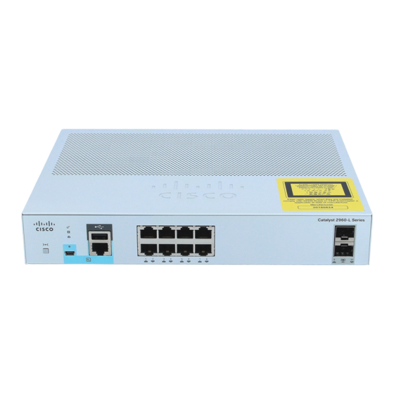
Cisco Catalyst 2960-L Series Hardware Installation Manual
8-port and 16-port switch
Hide thumbs
Also See for Catalyst 2960-L Series:
- Getting started manual (20 pages) ,
- Installation manual (22 pages) ,
- Hardware installation manual (72 pages)
Table of Contents
Advertisement
Advertisement
Table of Contents

Related Manuals for Cisco Catalyst 2960-L Series


Summary of Contents for Cisco Catalyst 2960-L Series
- Page 1 Cisco Catalyst 2960-L Series 8-Port and 16-Port Switch Hardware Installation Guide First Published: 2016-09-30 Americas Headquarters Cisco Systems, Inc. 170 West Tasman Drive San Jose, CA 95134-1706 http://www.cisco.com Tel: 408 526-4000 800 553-NETS (6387) Fax: 408 527-0883...
-
Page 2: Table Of Contents
Port LEDs and Modes PoE LED Console LEDs Port LEDs Rear Panel Internal Power Supply Security Slot Network Configurations C H A P T E R 2 Switch Installation Safety Warnings Cisco Catalyst 2960-L Series 8-Port and 16-Port Switch Hardware Installation Guide... - Page 3 10/100/1000 Port Connections Auto-MDIX Connections C H A P T E R 3 Troubleshooting Diagnosing Problems Switch POST Results Switch LEDs Switch Connections Bad or Damaged Cable Ethernet and Fiber-Optic Cables Cisco Catalyst 2960-L Series 8-Port and 16-Port Switch Hardware Installation Guide...
- Page 4 Configuring the Switch Using the Configuration Setup Wizard Quick Setup: Accessing the Configuration Setup Wizard Completing the Configuration Setup Wizard Configuring the Switch Using the CLI Accessing the CLI Through the Console Port Cisco Catalyst 2960-L Series 8-Port and 16-Port Switch Hardware Installation Guide...
- Page 5 Installing the Cisco Microsoft Windows 7 USB Driver Uninstalling the Cisco Microsoft Windows USB Driver Uninstalling the Cisco Microsoft Windows XP and 2000 USB Driver Uninstalling the Cisco Microsoft Windows 7 USB Driver Cisco Catalyst 2960-L Series 8-Port and 16-Port Switch Hardware Installation Guide...
- Page 6 Contents Cisco Catalyst 2960-L Series 8-Port and 16-Port Switch Hardware Installation Guide...
- Page 7 Cisco has more than 200 offices worldwide. Addresses and phone numbers are listed on the Cisco website at www.cisco.com/go/offices. Cisco and the Cisco logo are trademarks or registered trademarks of Cisco and/or its affiliates in the U.S. and other countries. To view a list of Cisco trademarks, go to this URL: www.cisco.com...
-
Page 9: Preface
[x | y] Optional alternative keywords are grouped in brackets and separated by vertical bars. {x | y} Required alternative keywords are grouped in braces and separated by vertical bars. Cisco Catalyst 2960-L Series 8-Port and 16-Port Switch Hardware Installation Guide... -
Page 10: Related Documentation
Use the statement number provided at the end of each warning to locate its translation in the translated safety warnings that accompanied this device. Statement 1071 SAVE THESE INSTRUCTIONS Related Documentation • Cisco SFP modules documentation, including compatibility matrixes, located at: Cisco Catalyst 2960-L Series 8-Port and 16-Port Switch Hardware Installation Guide... -
Page 11: Obtaining Documentation And Submitting A Service Request
Obtaining Documentation and Submitting a Service Request For information on obtaining documentation, submitting a service request, and gathering additional information, see the monthly What's New in Cisco Product Documentation, which also lists all new and revised Cisco technical documentation, at: http://www.cisco.com/c/en/us/td/docs/general/whatsnew/whatsnew.html... - Page 12 Preface Obtaining Documentation and Submitting a Service Request Cisco Catalyst 2960-L Series 8-Port and 16-Port Switch Hardware Installation Guide...
-
Page 13: Product Overview
C H A P T E R Product Overview The Cisco Catalyst 2960-L Series switches are fixed-configuration, Gigabit Ethernet switches that provide entry-level enterprise-class Layer 2 access for branch offices, conventional workspace, and out-of-wiring closet applications. Cisco Catalyst 2960-L Series switches provide support for the following features: •... -
Page 14: Front Panel
120W); 2 1-Gigabit small form-factor pluggable (SFP) module uplink slots. Front Panel This section describes the front panel components of a 8-port and 16-port Cisco Catalyst 2960-L switch. • 8 or 16 downlink Ethernet ports of one of these types: • 10/100/1000 •... -
Page 15: Poe Ports
The ports provide PoE support for devices compliant with IEEE 802.3af and IEEE 802.3at and also provide PoE support for Cisco IP Phones and Cisco Aironet Access Points. The PoE switch ports are Power Source equipment (PSE) and Power Device (PD) capable and source power to PD devices connected to the downlink ports. -
Page 16: 10/100/1000 Ports
• USB mini-Type B console port (5-pin connector). If you use the USB mini-Type B console port, the Cisco Windows USB device driver must be installed on any PC connected to the console port (for operation with Microsoft Windows). Mac OS X or Linux do not require special drivers. -
Page 17: Sfp Module Slots
SFP module slot. The SFP modules have LC connectors for fiber-optic connections or RJ-45 connectors for copper connections. The SFP slots support only SFP modules. For Cisco SFP modules documentation, including compatibility matrixes, refer to this URL: http://www.cisco.com/en/US/products/hw/modules/ps5455/products_device_support_tables_list.html... -
Page 18: System Led
Color System Status System is not powered on. Green System is operating normally. Amber System is receiving power but is not operating properly. Blinking Green POST is in progress. Cisco Catalyst 2960-L Series 8-Port and 16-Port Switch Hardware Installation Guide... -
Page 19: Port Leds And Modes
Port is blocked by STP and is not sending data. SPEED Port speed Port is operating at 10 Mb/s. Green Port is operating at 100 Mb/s. Blinking green Port is operating at 1000 Mb/s. Cisco Catalyst 2960-L Series 8-Port and 16-Port Switch Hardware Installation Guide... -
Page 20: Poe Led
RJ-45 console port is active. Port LEDs RJ-45 ports and SFP-module slots have port LEDs. These LEDs, as a group or individually, provide information about the switch and about the individual ports. Cisco Catalyst 2960-L Series 8-Port and 16-Port Switch Hardware Installation Guide... -
Page 21: Rear Panel
• Heat sink fins (PoE models only) Figure 5: Rear Panel of a Non-PoE Switch Security Slot A loop (for the optional power cord retainer) An AC power connector Cisco Catalyst 2960-L Series 8-Port and 16-Port Switch Hardware Installation Guide... -
Page 22: Internal Power Supply
The switches have security slots on the rear panel. You can install an optional cable lock, such as the type that is used to secure a laptop computer, to secure the switch. Cisco Catalyst 2960-L Series 8-Port and 16-Port Switch Hardware Installation Guide... -
Page 23: Network Configurations
See the switch software configuration guide for network configuration concepts and examples of using the switch to create dedicated network segments and interconnecting the segments through Fast Ethernet and Gigabit Ethernet connections. Cisco Catalyst 2960-L Series 8-Port and 16-Port Switch Hardware Installation Guide... - Page 24 Product Overview Network Configurations Cisco Catalyst 2960-L Series 8-Port and 16-Port Switch Hardware Installation Guide...
-
Page 25: Switch Installation
Read the wall-mounting instructions carefully before beginning installation. Failure to use the correct hardware or to follow the correct procedures could result in a hazardous situation to people and damage to the system. Statement 378 Cisco Catalyst 2960-L Series 8-Port and 16-Port Switch Hardware Installation Guide... -
Page 26: Safety Warnings
Statement 1024 Warning Only trained and qualified personnel should be allowed to install, replace, or service this equipment. Statement 1030 Cisco Catalyst 2960-L Series 8-Port and 16-Port Switch Hardware Installation Guide... - Page 27 Statement 1072 Warning No user-serviceable parts inside. Do not open. Statement 1073 Warning Installation of the equipment must comply with local and national electrical codes. Statement 1074 Cisco Catalyst 2960-L Series 8-Port and 16-Port Switch Hardware Installation Guide...
-
Page 28: Box Contents
Hot surface. Statement 1079 Box Contents This section lists the contents of the shipping box for an 8-port and 16-port Cisco Catalyst 2960-L switch. Figure 8: Box Contents of an 8-Port and 16-Port Cisco Catalyst 2960-L Switch 8-port or 16-port Cisco Catalyst 2960-L... -
Page 29: Tools And Equipment
• Altitude at the installation site is not greater than 10,000 feet. • For 10/100/1000 fixed ports, the cable length from a switch to a connected device cannot exceed 328 feet (100 meters). Cisco Catalyst 2960-L Series 8-Port and 16-Port Switch Hardware Installation Guide... -
Page 30: Verifying Switch Operation
When you connect the RPS to the switch, put the RPS in standby mode. Set the RPS to active mode during normal operation. Warning Attach only the following Cisco external power system to the switch: Cisco XPS 2200 Statement 387 Mounting the Switch Mounting on a Desk or Shelf Without Mounting Screws Step 1 Locate the adhesive strip with the rubber feet in the accessory kit. -
Page 31: On A Desk, Shelf, Or Wall (With Mounting Screws)
Step 7 Place the switch onto the mounting screws, and slide it forward until it locks in place. Figure 10: Mounting the Switch on Top of a Desk or Shelf Cisco Catalyst 2960-L Series 8-Port and 16-Port Switch Hardware Installation Guide... -
Page 32: Under A Desk- Or Shelf-Mounting
Place the switch upside down onto the mounting screws, and slide it forward until it locks in place. Warning To prevent airflow restriction, allow clearance around the ventilation openings to be at least: 3 in. (7.6 cm) Statement 1076 Cisco Catalyst 2960-L Series 8-Port and 16-Port Switch Hardware Installation Guide... -
Page 33: Wall-Mounting
Use a 0.144-inch (3.7 mm) or a #27 drill bit to drill a 1/2-inch (12.7 mm) hole in the two screw template slots. Step 6 Insert two screws in the slots on the screw template, and tighten them until they touch the top of the screw template. Cisco Catalyst 2960-L Series 8-Port and 16-Port Switch Hardware Installation Guide... - Page 34 Figure 13: Installing the Mounting Screws on the Wall Step 7 Remove the screw template from the wall. Step 8 Place the switch onto the mounting screws, and slide it down until it locks in place. Cisco Catalyst 2960-L Series 8-Port and 16-Port Switch Hardware Installation Guide...
-
Page 35: With A Mounting Tray
You can use the mounting tray by itself with mounting screws, or with a magnet. Mounting Tray with Screws You can use the mounting tray to secure the switch: • On a desk or shelf • Under a desk or shelf Cisco Catalyst 2960-L Series 8-Port and 16-Port Switch Hardware Installation Guide... - Page 36 Figure 15: Attaching the Tray to the Desk or Shelf Step 4 Place the switch onto the mounting screws, and slide the switch until it locks into place. Figure 16: Installing the Switch on the Mounting Tray Cisco Catalyst 2960-L Series 8-Port and 16-Port Switch Hardware Installation Guide...
-
Page 37: Mounting Tray With A Magnet
This example shows you how to mount the switch on a metal wall. You can use a similar procedure to mount the switch on, or under, a metal desk. Step 1 Place the switch on the mounting tray. Cisco Catalyst 2960-L Series 8-Port and 16-Port Switch Hardware Installation Guide... - Page 38 Do not wall-mount the switch with its front panel facing up. Following safety regulations, wall-mount the switch with its front panel facing down or to the side, to allow sufficient airflow and to provide easier access to the cables. Cisco Catalyst 2960-L Series 8-Port and 16-Port Switch Hardware Installation Guide...
-
Page 39: In A Rack
• If the rack is provided with stabilizing devices, install the stabilizers before mounting or servicing the unit in the rack. Statement 1006 Cisco Catalyst 2960-L Series 8-Port and 16-Port Switch Hardware Installation Guide... - Page 40 Warning To prevent airflow restriction, allow clearance around the ventilation openings to be at least: 3 in. (7.6 cm) Statement 1076 Cisco Catalyst 2960-L Series 8-Port and 16-Port Switch Hardware Installation Guide...
-
Page 41: On A Din Rail
To install the switch on a DIN rail, follow the instructions described in these sections: Attaching the DIN-Mount Tray to the Switch Step 1 Place the switch on the DIN rail mount. Cisco Catalyst 2960-L Series 8-Port and 16-Port Switch Hardware Installation Guide... -
Page 42: Mounting The Switch On A Din Rail
Do not install the switch with its front panel facing up. Following safety regulations, install the switch with its front panel facing down, to allow sufficient airflow and to provide easier access to the cables. Cisco Catalyst 2960-L Series 8-Port and 16-Port Switch Hardware Installation Guide... -
Page 43: Removing The Switch From A Din Rail
Removing the Switch from a DIN Rail Step 1 Ensure that power is removed from the switch, and disconnect all cables and connectors from the front panel of the switch. Cisco Catalyst 2960-L Series 8-Port and 16-Port Switch Hardware Installation Guide... -
Page 44: Installing The Power Cord Retainer (Optional)
Choose the sleeve size of the power cord retainer based on the thickness of the cord. The smaller sleeve can be snapped off and used for thin cords. Step 2 Slide the retainer around the AC power cord, and pass it around the loop on the switch. Cisco Catalyst 2960-L Series 8-Port and 16-Port Switch Hardware Installation Guide... - Page 45 Figure 28: Sliding the Retainer Through the Latch AC power cord Latch Smaller sleeve for thin power cords Step 4 Slide the retainer through the other latches to lock it. Cisco Catalyst 2960-L Series 8-Port and 16-Port Switch Hardware Installation Guide...
- Page 46 Detach the sleeve, and slide it over the power cord. Figure 30: Sleeve Around the Power Cord Smaller sleeve for thin power AC power cord cords Step 6 Secure the AC power cord by pressing on the retainer. Cisco Catalyst 2960-L Series 8-Port and 16-Port Switch Hardware Installation Guide...
-
Page 47: Installing The Cable Guard (Optional)
Installing the Cable Guard (Optional) The cable guard prevents tampering with the cables after the cables are installed. The cable guard (CMPCT-CBLE-GRD=) is not included with the switch, but you can order it from your Cisco representative. Note You can use the cable guard when the switch is mounted on a desk, under a desk, or on a wall. - Page 48 Loosen the number-10 Phillips pan-head screws, slide the cable guide out, and pivot it upwards so that you can install the cables. Figure 34: Pivoting the Cable Guard Upwards Cable guard Pivot direction for cable guard pivots Step 4 Attach the cables to the switch. Cisco Catalyst 2960-L Series 8-Port and 16-Port Switch Hardware Installation Guide...
- Page 49 (Optional) To attach the cable guard to the desk or wall, use a 0.144-inch (3.7 mm) or a #27 drill bit to drill 1/2-inch (12.7 mm) holes at each of the two mounting locations. Insert the supplied 0.5 in. (12.7 mm) number-8 Phillips wood screws and tighten them. Cisco Catalyst 2960-L Series 8-Port and 16-Port Switch Hardware Installation Guide...
-
Page 50: Installing Sfp Modules
Installing SFP Modules See the switch release notes on Cisco.com for the list of supported SFP modules. Use only Cisco SFP modules on the switch. Each Cisco module has an internal serial EEPROM that is encoded with security information. -
Page 51: Removing An Sfp Module
Disconnect the cable from the SFP module. For reattachment, note which cable connector plug is send (TX) and which is receive (RX). Step 3 Insert a dust plug into the optical ports of the SFP module to keep the optical interfaces clean. Cisco Catalyst 2960-L Series 8-Port and 16-Port Switch Hardware Installation Guide... -
Page 52: 10/100/1000 Poe And Poe+Port Connections
On a per-port basis, you can control whether or not a port automatically provides power when an IP phone or an access point is connected. To access an advanced PoE planning tool, use the Cisco Power Calculator available on Cisco.com at this URL: http://tools.cisco.com/cpc/launch.jsp... -
Page 53: 10/100/1000 Port Connections
Step 4 Repeat Steps 1 through 3 to connect each device. Many legacy powered devices, including older Cisco IP phones and access points that do not fully support Note IEEE 802.3af, might not support PoE when connected to the switches by a crossover cable. - Page 54 Switch to computer or server Switch to router Switch to IP phone 100BASE-TX and 1000BASE-T traffic requires twisted four-pair, Category 5 or higher. 10BASE-T traffic can use Category 3 cable or higher. Cisco Catalyst 2960-L Series 8-Port and 16-Port Switch Hardware Installation Guide...
-
Page 55: Troubleshooting
You can also get statistics from Device Manager, from the CLI, or from an SNMP workstation. Switch POST Results POST failures are usually fatal. Contact your Cisco technical support representative if your switch does not pass POST. Switch LEDs If you have physical access to the switch, look at the port LEDs for troubleshooting information about the switch. -
Page 56: Ethernet And Fiber-Optic Cables
• Use the show interfaces privileged EXEC command to see if the port is in error-disabled, disabled, or shutdown. Reenable the port if necessary. • Verify that the power supply installed in the switch meets the power requirements of your connected devices. Cisco Catalyst 2960-L Series 8-Port and 16-Port Switch Hardware Installation Guide... -
Page 57: Sfp Module
PoE fault. SFP Module Use only Cisco SFP modules in the switch. Each Cisco module has an internal serial EEPROM that is encoded with security information. This encoding provides a way for Cisco to identify and validate that the module meets the requirements for the switch. -
Page 58: Switch Performance
Finding the Switch Serial Number If you contact Cisco Technical Assistance, you need to know the switch serial number. You can also use the show version privileged EXEC command to see the switch serial number. - Page 59 Troubleshooting Finding the Switch Serial Number Figure 39: Serial Number Location PID number Serial number MAC address Product label CLEI code Cisco Catalyst 2960-L Series 8-Port and 16-Port Switch Hardware Installation Guide...
- Page 60 Troubleshooting Finding the Switch Serial Number Cisco Catalyst 2960-L Series 8-Port and 16-Port Switch Hardware Installation Guide...
-
Page 61: Technical Specifications
• 1.73 x 8.45 x 10.56 in. (4.4 x 21.5 x 26.8 cm) (Cisco Catalyst 2960L-16TS-LL) • 1.73 x 9.45 x 10.56 in. (4.4 x 24 x 26.8 cm) (Cisco Catalyst 2960L-16PS-LL) Cisco Catalyst 2960-L Series 8-Port and 16-Port Switch Hardware Installation Guide... -
Page 62: Environmental Specifications
• 0.79 to 1.45 A, 50 to 60 Hz (Cisco Catalyst 2960L-16PS-LL) Power rating • 0.04 KVA (Cisco Catalyst 2960L-8TS-LL) • 0.11 KVA (Cisco Catalyst 2960L-8PS-LL) • 0.05 KVA (Cisco Catalyst 2960L-16TS-LL) • 0.19 KVA (Cisco Catalyst 2960L-16PS-LL) Cisco Catalyst 2960-L Series 8-Port and 16-Port Switch Hardware Installation Guide... -
Page 63: Poe Power Consumption
Consumption with Available PoE (Maximum Power without PoE Wattage for BTU/hr) Cisco Catalyst 2960L-8TS-LL 15.54 Cisco Catalyst 2960L-8PS-LL 89.02 Cisco Catalyst 18.9 2960L-16TS-LL Cisco Catalyst 157W 120W 156.7 2960L-16PS-LL Cisco Catalyst 2960-L Series 8-Port and 16-Port Switch Hardware Installation Guide... - Page 64 Technical Specifications PoE Power Consumption Cisco Catalyst 2960-L Series 8-Port and 16-Port Switch Hardware Installation Guide...
-
Page 65: Connector And Cable Specifications
Connector Specifications 10/100/1000 Ports (Including PoE) All 10/100/1000 ports use standard RJ-45 connectors and Ethernet pinouts. Figure 40: 10/100/1000 Port Pinouts SFP Module Connectors Figure 41: Duplex LC Cable Connector Cisco Catalyst 2960-L Series 8-Port and 16-Port Switch Hardware Installation Guide... -
Page 66: Cables And Adapters
Each port must match the wave-length specifications on the other end of the cable, and the cable must not exceed the stipulated cable length. Copper 1000BASE-T SFP module transceivers use standard four twisted-pair, Category 5 cable at lengths up to 328 feet (100 meters). Cisco Catalyst 2960-L Series 8-Port and 16-Port Switch Hardware Installation Guide... -
Page 67: Cable Pinouts
The wire connected to the pin on the outside of the left plug should be a different color from the wire connected to the pin on the inside of the right plug. Cisco Catalyst 2960-L Series 8-Port and 16-Port Switch Hardware Installation Guide... -
Page 68: Console Port Adapter Pinouts
RJ-45-to-DB-9 Terminal Adapter Console Device Signal DB-9 Pin Signal Table 8: Console Port Signaling with a DB-25 Adapter Switch Console Port (DTE) RJ-45-to-DB-25 Terminal Adapter Console Device Signal DB-25 Pin Signal Cisco Catalyst 2960-L Series 8-Port and 16-Port Switch Hardware Installation Guide... - Page 69 Connector and Cable Specifications Connector and Cable Specifications Switch Console Port (DTE) RJ-45-to-DB-25 Terminal Adapter Console Device Signal DB-25 Pin Signal Cisco Catalyst 2960-L Series 8-Port and 16-Port Switch Hardware Installation Guide...
- Page 70 Connector and Cable Specifications Connector and Cable Specifications Cisco Catalyst 2960-L Series 8-Port and 16-Port Switch Hardware Installation Guide...
-
Page 71: Configuring The Switch
If your device supports Bluetooth, it loads with the initial setup tasks preconfigured. Connect your PC to the device using Bluetooth. In your Web browser, enter the IP address 172.16.0.1. Enter the following default credentials: username: cisco, password: cisco and press Enter. Cisco Catalyst 2960-L Series 8-Port and 16-Port Switch Hardware Installation Guide... - Page 72 Configuring the Switch Configuring the Switch Mode button SYST LED (system) STAT LED (status) SPEED LED PoE LED Console LED Port LEDs Only on switch models that support PoE. Cisco Catalyst 2960-L Series 8-Port and 16-Port Switch Hardware Installation Guide...
-
Page 73: Completing The Configuration Setup Wizard
Confirm that the STAT LED is solid green. This indicates that POST is complete. If the STAT LED turns amber, the device failed POST. Reconnect the AC power cord to the AC power connector of your device and to a grounded AC outlet. If the STAT LED still does not turn green, contact your Cisco representative or retailer. Step 3 Press and hold the Mode button for 3 seconds. -
Page 74: Connecting The Rj-45 Console Port
HyperTerminal or ProcommPlus, makes communication between the switch and your PC or terminal possible. 4. Configure the baud rate and character format of the PC or terminal to match the console port default characteristics: Cisco Catalyst 2960-L Series 8-Port and 16-Port Switch Hardware Installation Guide... -
Page 75: Installing The Cisco Microsoft Windows Usb Device Driver
Installing the Cisco Microsoft Windows XP USB Driver SUMMARY STEPS 1. Obtain the Cisco USB console driver file from the Cisco.com web site and unzip it. 2. If using 32-bit Windows XP, double-click the setup.exe file in the Windows_32 folder. If using 64-bit Windows XP, double-click the setup(x64).exe file in the Windows_64 folder. -
Page 76: Installing The Cisco Microsoft Windows 2000 Usb Driver
Installing the Cisco Microsoft Windows 2000 USB Driver SUMMARY STEPS 1. Obtain the Cisco USB console driver file from the Cisco.com web site and unzip it. 2. Double-click the setup.exe file. 3. The Cisco Virtual Com InstallShield Wizard begins. Click Next. -
Page 77: Installing The Cisco Microsoft Windows 7 Usb Driver
Installing the Cisco Microsoft Windows 7 USB Driver SUMMARY STEPS 1. Obtain the Cisco USB console driver file from the Cisco.com web site and unzip it. 2. If using 32-bit Windows 7, double-click the setup.exe file in the Windows_32 folder. If using 64-bit Windows 7, double-click the setup(x64).exe file in the Windows_64 folder. -
Page 78: Uninstalling The Cisco Microsoft Windows 7 Usb Driver
3. When the Program Maintenance window appears, select the Remove radio button. Click Next. 4. When the Remove the Program window appears, click Remove. 5. When the InstallShield Wizard Completed window appears, click Finish. Cisco Catalyst 2960-L Series 8-Port and 16-Port Switch Hardware Installation Guide... - Page 79 When the Remove the Program window appears, click Remove. Note If a User Account Control warning appears, click Allow - I trust this program to proceed. Step 5 When the InstallShield Wizard Completed window appears, click Finish. Cisco Catalyst 2960-L Series 8-Port and 16-Port Switch Hardware Installation Guide...
- Page 80 Configuring the Switch Configuring the Switch Cisco Catalyst 2960-L Series 8-Port and 16-Port Switch Hardware Installation Guide...