Table of Contents
Advertisement
Quick Links
Catalyst 2960-X and 2960-XR Switch Hardware Installation Guide
First Published: August 05, 2013
Last Modified: November 20, 2013
Americas Headquarters
Cisco Systems, Inc.
170 West Tasman Drive
San Jose, CA 95134-1706
USA
http://www.cisco.com
Tel: 408 526-4000
800 553-NETS (6387)
Fax: 408 527-0883
Text Part Number: OL-28309-02
Advertisement
Table of Contents

Related Manuals for Cisco Catalyst 2960X-48FPD-L


Summary of Contents for Cisco Catalyst 2960X-48FPD-L
- Page 1 Catalyst 2960-X and 2960-XR Switch Hardware Installation Guide First Published: August 05, 2013 Last Modified: November 20, 2013 Americas Headquarters Cisco Systems, Inc. 170 West Tasman Drive San Jose, CA 95134-1706 http://www.cisco.com Tel: 408 526-4000 800 553-NETS (6387) Fax: 408 527-0883...
- Page 2 Cisco and the Cisco logo are trademarks or registered trademarks of Cisco and/or its affiliates in the U.S. and other countries. To view a list of Cisco trademarks, go to this URL: www.cisco.com/go/trademarks . Third-party trademarks mentioned are the property of their respective owners. The use of the word partner does not imply a partnership relationship between Cisco and any other company.
-
Page 3: Table Of Contents
RPS LED IRPS LED Master LED Port LEDs and Modes STACK LED Console LEDs Ethernet Management Port LED Rear Panel FlexStack-Plus Ports and LEDs RPS Connector Cisco RPS 2300 AC Power Connector Catalyst 2960-X and 2960-XR Switch Hardware Installation Guide OL-28309-02... - Page 4 Contents Power Supply Modules (Applies to the Catalyst 2960-XR Switches) Management Options Network Configurations Switch Installation C H A P T E R 2 Safety Warnings Box Contents Tools and Equipment Installation Guidelines Verifying Switch Operation Planning and Installing a Switch Stack (Optional) Stack Guidelines Installing the FlexStack-Plus Module Stack Cabling...
- Page 5 Contents Connecting to 1000BASE-T SFP 10/100/1000 PoE+ Port Connections 10/100/1000 Port Connections Auto-MDIX Connections Where to Go Next Power Supply Installation C H A P T E R 3 Power Supply Module Overview Installation Guidelines Installing or Replacing an AC Power Supply Finding the Serial Number Troubleshooting C H A P T E R 4...
- Page 6 Installing the Cisco Microsoft Windows XP USB Driver Installing the Cisco Microsoft Windows 2000 USB Driver Installing the Cisco Microsoft Windows Vista and Windows 7 USB Driver Uninstalling the Cisco Microsoft Windows USB Driver Uninstalling the Cisco Microsoft Windows XP and 2000 USB Driver Using the Setup.exe Program...
-
Page 7: Preface
Preface • Document Conventions, page vii • Related Documentation, page ix • Obtaining Documentation and Submitting a Service Request, page ix Document Conventions This document uses the following conventions: Convention Description ^ or Ctrl Both the ^ symbol and Ctrl represent the Control (Ctrl) key on a keyboard. For example, the key combination ^D or Ctrl-D means that you hold down the Control key while you press the D key. - Page 8 Preface Document Conventions Convention Description {x | y} Required alternative keywords are grouped in braces and separated by vertical bars. [x {y | z}] Nested set of square brackets or braces indicate optional or required choices within optional or required elements. Braces and a vertical bar within square brackets indicate a required choice within an optional element.
-
Page 9: Related Documentation
Obtaining Documentation and Submitting a Service Request For information on obtaining documentation, submitting a service request, and gathering additional information, see the monthly What's New in Cisco Product Documentation, which also lists all new and revised Cisco technical documentation, at: http://www.cisco.com/en/US/docs/general/whatsnew/whatsnew.html... - Page 10 Preface Obtaining Documentation and Submitting a Service Request Catalyst 2960-X and 2960-XR Switch Hardware Installation Guide OL-28309-02...
-
Page 11: Product Overview
Product Overview The Catalyst 2960-X and 2960-XR family of switches are Ethernet switches to which you can connect devices such as Cisco IP Phones, Cisco Wireless Access Points, workstations, and other network devices such as servers, routers, and other switches. - Page 12 24 10/100/1000 (8 PoE- with PoE budget of 110 W) ports, fanless, 2 10/100/1000BaseT copper uplinks, and 2 SFP module slots. 1 Support Cisco FlexStack-Plus technology. 2 SFP+ = 10-Gigabit uplink. 3 SFP = 1-Gigabit uplink. Table 2: Catalyst 2960-XR Switch Models and Descriptions...
-
Page 13: Front Panel
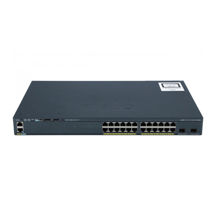
Product Overview Front Panel Switch Model Supported Description Software Image Catalyst 2960XR-24TD-I IP Lite 24 10/100/1000 and 2 SFP+ module slots, 250-W power supply. Catalyst 2960XR-48FPS-I IP Lite 48 10/100/1000 PoE+ ports (PoE budget of 740 W) and 4 SFP module slots, 1025-W power supply. Catalyst 2960XR-48LPS-I IP Lite 48 10/100/1000 PoE+ ports (PoE budget of 370 W) and 4... - Page 14 Product Overview Front Panel The Catalyst 2960X-48FPD-L switch is shown here as an example. Other switches have similar components. Figure 1: Catalyst 2960X-48FPD-L Front Panel Mode button and switch LEDs SFP module slots USB mini-Type B (console) port 10/100/1000 PoE+ ports...
-
Page 15: Poe And Poe+ Ports
The ports provide PoE+ support for devices compliant with IEEE 802.3af, IEEE 802.3at, and ePoE and also provide Cisco prestandard PoE support for Cisco IP Phones and Cisco Aironet Access Points. The maximum switch power output is either 740 W or 370 W, depending on the switch model. Intelligent power management allows flexible power allocation across all ports. -
Page 16: Management Ports
RJ-45 console interface speeds. If you use the USB mini-Type B console port, the Cisco Windows USB device driver must be installed on any PC connected to the console port (for operation with Microsoft Windows). Mac OS X or Linux do not require special drivers. -
Page 17: Usb Type A Port
The USB Type A port provides these features: The port supports Cisco USB flash drives with capacities from 128 MB to 8 GB (USB devices with port densities of 128 MB, 256 MB, 1 GB, 4 GB, 8 GB are supported). When combined with stacking, you can upgrade other switches in the stack from an USB key inserted in any switch within the stack. - Page 18 Product Overview LEDs This figure shows the switch LEDs and the Mode button that you use to select a port mode. Figure 4: Switch LEDs and Mode Button for the Catalyst 2960-X Switch RPS LED PoE LED SPEED LED USB mini-Type B console port LED STAT LED USB Type A port SYS LED...
- Page 19 Product Overview LEDs 4 RPS = redundant power system—only on switch models that support RPS. 5 Only on switch models that support PoE. 6 Only on switch models that support stacking. This figure shows the switch LEDs and the Mode button that you use to select a port mode. Figure 5: Switch LEDs and Mode Button for the Catalyst 2960-XR Switch IRPS LED PoE LED...
-
Page 20: System Led
Product Overview LEDs Mode button CONSOLE LED Master LED USB Type A port STACK LED Port LEDs 7 Only on switch models that support PoE. 8 Only on switch models that support stacking. System LED Table 3: System LED Color System Status System is not powered on. -
Page 21: Irps Led
Product Overview LEDs Color RPS Status Blinking amber The power supply in a switch has failed, and the RPS is providing power to the switch (redundancy has been allocated to this device). IRPS LED The IRPS LED is only available on Catalyst 2960-XR switches. Table 5: IRPS LED Color RPS Status... - Page 22 PoE is off due to a fault. Noncompliant cabling or powered devices can cause a PoE port fault. Use only standard-compliant cabling to connect Cisco prestandard IP Phones and wireless access points or IEEE 802.3af-compliant devices. You must remove any cable or device that causes a PoE fault.
- Page 23 Port is operating at 100 Mb/s. Blinking green Port is operating at 1000 Mb/s. SFP+ module ports (Applies to the Catalyst 2960X-48FPD-L, 2960X-48LPD-L, 2960X-24PD-L, 2960X-48TD-L, and the 2960X-24TD-L switches.) SFP+ module ports (Applies to the Catalyst 2960XR-48FPD-I, 2960XR-48LPD-I, 2960XR-24PD-I, 2960XR-48TD-I, and the 2960XR-24TD-I switches.) Port is not operating.
-
Page 24: Stack Led
Product Overview LEDs Port Mode Port LED Color Meaning No stack member has that member number. STACK (stack member) Blinking green Stack member number. Green Member numbers of other stack member switches. If your switches are stacked and you press the Mode button on any switch, all the switches display the same selected mode. -
Page 25: Console Leds
Product Overview Rear Panel When you select the STACK LED, the respective STACK LEDs are green when the stack ports (on the switch rear panel) are up, and the respective Stack LEDs are amber when the ports are down. SFP+ module port LEDs 1 and 2 on the switch show the status for stack ports 1 and 2, respectively. - Page 26 Product Overview Rear Panel The FlexStack-Plus module slot is not available on the Catalyst 2960X-48TS-LL and 2960X-24TS-LL Note switches. The FlexStack module slot, fan exhaust, and the RPS connector are not available on the Catalyst 2960-X 24PSQ-L switch. Figure 7: Catalyst 2960-X Switch Rear Panel FlexStack-Plus module slot and cover RPS Connector Fan Exhaust...
-
Page 27: Flexstack-Plus Ports And Leds
Product Overview FlexStack-Plus Ports and LEDs FlexStack-Plus module slot and cover PS OK LED Power supply slot (with blank module) AC power connector on the power supply module AC OK LED FlexStack-Plus Ports and LEDs The stacking-capable switch models support stacking with the optional stack kit. It has the FlexStack-Plus module (hot-swappable) that inserts in the slot located in the switch rear panel, and a 0.5-meter FlexStack cable to connect the FlexStack-Plus module ports. -
Page 28: Rps Connector
The Cisco RPS 2300 has two output levels: –52 V and 12 V with a total maximum output power of 2300 W. All supported and connected switches can simultaneously communicate with the RPS 2300. You can configure these RPS 2300 features through the switch software: •... -
Page 29: Ac Power Connector
Product Overview AC Power Connector AC Power Connector Note This applies to the Catalyst 2960-X switches. The switch is powered through the internal power supply. The internal power supply is an autoranging unit that supports input voltages between 100 and 240 VAC. Use the supplied AC power cord to plug it into an AC power outlet. -
Page 30: Management Options
Cisco Network Assistant is a PC-based network management GUI application for LANs of small and medium-sized businesses. You can use the GUI to configure and manage switch clusters or standalone switches. Cisco Network Assistant is available at no cost and can be downloaded from this URL: http:/ /www.cisco.com/en/US/products/ps5931/index.html... -
Page 31: Network Configurations
Product Overview Network Configurations Network Configurations See the switch software configuration guide on Cisco.com for network configuration concepts and examples of using the switch to create dedicated network segments and interconnecting the segments through Fast Ethernet and Gigabit Ethernet connections. - Page 32 Product Overview Network Configurations Catalyst 2960-X and 2960-XR Switch Hardware Installation Guide OL-28309-02...
-
Page 33: Switch Installation
Safety Warnings This section includes the basic installation caution and warning statements. Read this section before you start the installation procedure. Translations of the warning statements appear in the RCSI guide on Cisco.com. Catalyst 2960-X and 2960-XR Switch Hardware Installation Guide... - Page 34 Statement 378 If a Cisco external power system is not connected to the switch, install the provided connector cover on Warning the back of the switch.
- Page 35 Switch Installation Safety Warnings Class 1 laser product. Statement 1008 Warning Warning This unit is intended for installation in restricted access areas. A restricted access area can be accessed only through the use of a special tool, lock and key, or other means of security. Statement 1017 Warning The plug-socket combination must be accessible at all times, because it serves as the main disconnecting device.
-
Page 36: Box Contents
Applies to the Catalyst 2960X-24PSQ-L switches. Box Contents The switch getting started guide describes the box contents. If any item is missing or damaged, contact your Cisco representative or reseller for support. Tools and Equipment Obtain these necessary tools and equipment: •... -
Page 37: Verifying Switch Operation
◦ Access to the rear of the rack is sufficient for connecting FlexStack cables to stacked switches, or connecting the optional Cisco Redundant Power Supply (RPS) 2300. • Cabling is away from sources of electrical noise, such as radios, power lines, and fluorescent lighting fixtures. -
Page 38: Planning And Installing A Switch Stack (Optional)
The FlexStack-Plus module is hot-swappable and can be inserted while the switch is powered on. • Order the appropriate cable from your Cisco sales representative. The length of FlexStack cable depends on your configuration. These are the different sizes available:... -
Page 39: Installing The Flexstack-Plus Module
Switch Installation Installing the FlexStack-Plus Module ◦ CAB-STK-E-0.5M= (0.5-meter cable) ◦ CAB-STK-E-1M= (1-meter cable) ◦ CAB-STK-E-3M= (3-meter cable) • Make sure that you have access to the switch rear panel and to the rear of the rack. Installing the FlexStack-Plus Module The switch should always have a blank module installed when a FlexStack-Plus module is not used. - Page 40 Switch Installation Installing the FlexStack-Plus Module Step 3 Secure the screws on each side of the module. Avoid overtightening the Note screws. Catalyst 2960-X and 2960-XR Switch Hardware Installation Guide OL-28309-02...
-
Page 41: Stack Cabling
Switch Installation Stack Cabling Stack Cabling These figures show the switches stacked in a vertical rack or on a table. The connections are redundant. A Catalyst 2960-X switch is shown in the examples, the Catalyst 2960-XR switch can be stacked in the same way. -
Page 42: Stack Bandwidth And Partitioning Examples
Switch Installation Stack Bandwidth and Partitioning Examples Stack Bandwidth and Partitioning Examples This figure shows a stack that provides full bandwidth with redundant connections. Figure 12: Stack with Full Bandwidth Connections This figure shows a stack with incomplete stack cabling connections. This stack provides only half bandwidth and does not have redundant connections. -
Page 43: Power-On Sequence For Switch Stacks
• Power off a switch before you add it to or remove it from an existing switch stack. For conditions that can cause a stack master reelection or to manually elect the stack master, see the Catalyst 2960-X Switch Stacking Configuration Guide or Catalyst 2960-XR Switch Stacking Configuration Guide on Cisco.com. Installing the Switch Rack-Mounting Installation in other than 19-inch racks requires a bracket kit not included with the switch. - Page 44 • If the rack is provided with stabilizing devices, install the stabilizers before mounting or servicing the unit in the rack. Statement 1006 This figure shows the standard 19-inch brackets and other optional mounting brackets. You can order the optional brackets from your Cisco sales representative. Figure 16: Rack-Mounting Brackets 19-inch brackets 23-inch brackets...
-
Page 45: Attaching The Rack-Mount Brackets For The Catalyst 2960-X Switches
Switch Installation Rack-Mounting Attaching the Rack-Mount Brackets for the Catalyst 2960-X Switches Procedure Use two Phillips flat-head screws to attach the long side of the bracket to each side of the switch. Figure 17: Attaching Brackets for 19-inch Racks Front-mounting position Mid-mounting position Number-8 Phillips flat-head screws (48-2927-01) Rear-mounting position... -
Page 46: Attaching The Rack-Mount Brackets For The Catalyst 2960-Xr Switches
Switch Installation Rack-Mounting Attaching the Rack-Mount Brackets for the Catalyst 2960-XR Switches Procedure Use four Phillips flat-head screws to attach the long side of the bracket to each side of the switch. Figure 18: Attaching Brackets for 19-inch Racks Front-mounting position Mid-mounting position Number-8 Phillips flat-head screws (48-2927-01) Rear-mounting position... -
Page 47: Mounting In A Rack
Switch Installation Rack-Mounting Mounting in a Rack Procedure Step 1 Use the four supplied Phillips machine screws to attach the brackets to the rack. Step 2 Use the black Phillips machine screw to attach the cable guide to the left or right bracket. Cable guide Number-12 Phillips pan-head screws (48-0523-01) or Number-10 Phillips pan-head... -
Page 48: Wall-Mounting
Switch Installation Wall-Mounting Front-mounting position Rear-mounting position Wall-Mounting Read the wall-mounting instructions carefully before beginning installation. Failure to use the correct Warning hardware or to follow the correct procedures could result in a hazardous situation to people and damage to the system. Statement 378 Attaching the Brackets for Wall-Mounting Procedure Step 1... -
Page 49: Attaching The Rps Connector Cover
Switch Installation Wall-Mounting Attaching the RPS Connector Cover This section only applies to the switches that have an RPS port. If an RPS is not connected to the switch, install an RPS connector cover on the back of the switch. Statement Warning Before You Begin Note... -
Page 50: Mounting On A Wall
Switch Installation Wall-Mounting Mounting on a Wall For the best support of the switch and cables, make sure that the switch is attached securely to wall studs or to a firmly attached plywood-mounting backboard. Mount the switch with the front panel facing down. Warning Read the wall-mounting instructions carefully before beginning installation. -
Page 51: Installing The Switch On A Table Or Shelf
This is only supported on the stack-capable switches. Note Caution Use only approved cables, and connect only to other Catalyst 2960-X or 2960-S switches. Equipment might be damaged if connected to other nonapproved Cisco cables or equipment. Catalyst 2960-X and 2960-XR Switch Hardware Installation Guide OL-28309-02... -
Page 52: Removing A Flexstack Cable
Switch Installation Removing a FlexStack Cable Procedure Step 1 Remove the dust covers from the FlexStack cables, and store them for future use. Step 2 Insert one end of the FlexStack cable into the stack port of the first switch. Insert the other end of the cable into the stack port on the other switch. -
Page 53: Installing The Power Cord Retainer (Optional)
This section applies only to the Catalyst 2960-X switches. Note The power cord retainer is optional (part number [PWR-CLP=]). You can order it when you order your switch, or you can order it later from your Cisco representative. Procedure Step 1 Choose the sleeve size of the power cord retainer based on the thickness of the cord. - Page 54 Switch Installation Installing the Power Cord Retainer (Optional) Step 3 Slide the retainer through the first latch. Figure 23: Sliding the Retainer Through the Latch AC power cord Latch Smaller sleeve for thin power cords Step 4 Slide the retainer through the other latches to lock it. Figure 24: Locking the Retainer AC power cord Latches...
-
Page 55: Installing Sfp And Sfp+ Modules
The SFP+ slots support both SFP and SFP+ modules. See the switch release notes on Cisco.com for the list of supported SFP modules. Use only Cisco SFP modules on the switch. Each Cisco module has an internal serial EEPROM that is encoded with security information. -
Page 56: Installing An Sfp Or Sfp+ Module
Switch Installation Installing an SFP or SFP+ Module For information about installing, removing, cabling, and troubleshooting SFP modules, see the module documentation that shipped with your device. Related Topics SFP and SFP+ Module Slots, on page 7 Installing an SFP or SFP+ Module Before You Begin When installing SFP or SFP+ modules, observe these guidelines: •... -
Page 57: Removing An Sfp Or Sfp+ Module
Switch Installation Removing an SFP or SFP+ Module Step 3 If the module has a bale-clasp latch, move it to the open, unlocked position. Step 4 Align the module in front of the slot opening, and push until you feel the connector snap into place. Step 5 If the module has a bale-clasp latch, close it. -
Page 58: Connecting To Fiber-Optic Sfp And Sfp+ Modules
Switch Installation Connecting to Fiber-Optic SFP and SFP+ Modules Connecting to Fiber-Optic SFP and SFP+ Modules Class 1 laser product. Statement 1008 Warning Do not remove the rubber plugs from the SFP or SFP+ module port or the rubber caps from the fiber-optic Caution cable until you are ready to connect the cable. -
Page 59: Connecting To 1000Base-T Sfp
The automatic medium-dependent interface crossover (auto-MDIX) feature is enabled by default. For Note configuration information for this feature, see the switch software configuration guide or the switch command reference on Cisco.com. Caution To prevent ESD damage, follow your normal board and component handling procedures. -
Page 60: 10/100/1000 Poe+ Port Connections
On a per-port basis, you can control whether or not a port automatically provides power when an IP phone or an access point is connected. To access an advanced PoE planning tool, use the Cisco Power Calculator available on Cisco.com at this URL: http://tools.cisco.com/cpc/launch.jsp... -
Page 61: 10/100/1000 Port Connections
Step 4 Repeat Steps 1 through 3 to connect each device. Many legacy powered devices, including older Cisco IP phones and access points that do not fully Note support IEEE 802.3af, might not support PoE when connected to the switches by a crossover cable. -
Page 62: Where To Go Next
GUI, you can configure and monitor a switch cluster or an individual switch. • Use the CLI to configure the switch as a member of a cluster or as an individual switch from the console. • Use the Cisco Prime Infrastructure application. Catalyst 2960-X and 2960-XR Switch Hardware Installation Guide... -
Page 63: Chapter
C H A P T E R Power Supply Installation This chapter applies only to the Catalyst 2960-XR switches. It contains these topics: • Power Supply Module Overview, page 53 • Installation Guidelines, page 56 • Installing or Replacing an AC Power Supply, page 57 •... -
Page 64: Power Supply Installation
Power Supply Installation Power Supply Module Overview Each AC power supply module has a power cord for connection to an AC power outlet. Figure 30: PWR-C2-1025WAC Power Supply AC OK LED AC power cord connector PS OK LED Release latch AC power cord retainer Power supply Figure 31: PWR-C2-640WAC Power Supply... -
Page 65: Power Supply Module Overview
Power Supply Installation Power Supply Module Overview PS OK LED Release latch AC power cord retainer Power supply Figure 32: PWR-C2-250WAC Power Supply AC OK LED AC power cord connector PS OK LED Release latch AC power cord retainer Power supply Catalyst 2960-X and 2960-XR Switch Hardware Installation Guide OL-28309-02... -
Page 66: Installation Guidelines
Power Supply Installation Installation Guidelines If no power supply is installed in a power supply slot, install a power supply slot cover. Figure 33: Power Supply Slot Cover Release handles Retainer clips The power supply modules have two status LEDs. AC OK Description PS OK... -
Page 67: Installing Or Replacing An Ac Power Supply
Only trained and qualified personnel should be allowed to install, replace, or service this equipment. Warning Statement 1030 If a Cisco external power system is not connected to the switch, install the provided connector cover on Warning the back of the switch. Statement 386... -
Page 68: Power Supply Installation
Power Supply Installation Installing or Replacing an AC Power Supply Step 5 Insert the new power supply into the power-supply slot, and gently push it into the slot. When correctly inserted, the 250-W and 640-W power supplies (excluding the power cord retainer) are flush with the switch rear panel. -
Page 69: Finding The Serial Number
Finding the Serial Number Finding the Serial Number If you contact Cisco Technical Assistance, you need to know the switch serial number. You can also use the show version privileged EXEC command to see the switch serial number. Figure 36: 1025-W AC Power Supply Serial Number... -
Page 70: Power Supply Installation
Power Supply Installation Finding the Serial Number Catalyst 2960-X and 2960-XR Switch Hardware Installation Guide OL-28309-02... -
Page 71: Troubleshooting
You can also get statistics from Device Manager, from the CLI, or from an SNMP workstation. Switch POST Results POST failures are usually fatal. Contact your Cisco technical support representative if your switch does Note not pass POST. -
Page 72: Switch Connections
Troubleshooting Switch Connections Switch Connections Bad or Damaged Cable Always examine the cable for marginal damage or failure. A cable might be just good enough to connect at the physical layer, but it could corrupt packets as a result of subtle damage to the wiring or connectors. You can identify this situation because the port has many packet errors or the port constantly flaps (loses and regains link). -
Page 73: 10/100/1000 Port Connections
SFP and SFP+ Module Use only Cisco SFP or SFP+ modules in the switch. Each Cisco module has an internal serial EEPROM that is encoded with security information. This encoding provides a way for Cisco to identify and validate that the module meets the requirements for the switch. -
Page 74: Interface Settings
Troubleshooting Switch Performance Interface Settings Verify that the interface is not disabled or powered off. If an interface is manually shut down on either side of the link, it does not come up until you reenable the interface. Use the show interfaces privileged EXEC command to see if the interface is error-disabled, disabled, or shutdown on either side of the connection. -
Page 75: Cabling Distance
Troubleshooting Clearing the Switch IP Address and Configuration To troubleshoot autonegotiation problems, try manually setting both sides of the connection. If this does not solve the problem, there could be a problem with the firmware or software on your NIC. You can resolve this by upgrading the NIC driver to the latest version. -
Page 76: Finding The Serial Number
Finding the Serial Number Finding the Serial Number If you contact Cisco Technical Assistance, you need to know the switch serial number. You can also use the show version privileged EXEC command to see the switch serial number. Figure 38: Serial Number Location for the Catalyst 2960-X Switches... -
Page 77: Replacing A Failed Stack Member
If you had manually set the member numbers for any stack members, you need to manually assign the replacement switch with the same member number as the failed switch. See the Catalyst 2960-X Switch Stacking Command Reference on Cisco.com. Catalyst 2960-X and 2960-XR Switch Hardware Installation Guide... - Page 78 Troubleshooting Replacing a Failed Stack Member Catalyst 2960-X and 2960-XR Switch Hardware Installation Guide OL-28309-02...
-
Page 79: Appendix A Technical Specifications
A P P E N D I X Technical Specifications This appendix contains these topics: • Environmental Specifications, page 69 • Specifications for the Catalyst 2960-X Switches, page 70 • Specifications for the Catalyst 2960-XR Switches, page 74 Environmental Specifications This table describes the environmental specifications. -
Page 80: Specifications For The Catalyst 2960-X Switches
100 to 240 VAC (autoranging) AC input voltage • 9 to 4 A, 50 to 60 Hz (Catalyst 2960X-48FPD-L) • 5 to 2 A, 50 to 60 Hz (Catalyst 2960X-48LPD-L) • 5 to 2 A, 50 to 60 Hz (Catalyst 2960X-24PD-L) •... - Page 81 Specifications for the Catalyst 2960-X Switches DC input voltage for RPS 2300 • +12 V @ 4 A, –53 V @ 15 A (Catalyst 2960X-48FPD-L) • +12 V @ 4 A, –53 V @ 8 A (Catalyst 2960X-48LPD-L) • +12 V @ 3A, –53 V @ 8 A (Catalyst 2960X-24PD-L) •...
- Page 82 Technical Specifications Specifications for the Catalyst 2960-X Switches Physical Dimensions Weight • 12.9 lb (5.8 kg) (Catalyst 2960X-48FPD-L) • 12.8 lb (5.8 kg) (Catalyst 2960X-48LPD-L) • 12.7 lb (5.8 kg) (Catalyst 2960X-24PD-L) • 13.2 (6.0 kg) (Catalyst 2960X-48FPS-L) • 12.9 lb (5.8 kg) (Catalyst 2960X-48LPS-L) •...
- Page 83 13 Power consumption values for the power consumed internally by the switch at 120 VAC 60 Hz. The information is based on the rating of the power supply (maximum) and does not reflect the actual measured consumption numbers. For the actual power consumption based on measurement, see the data sheet at: http://www.cisco.com/en/US/prod/collateral/switches/ps5718/ps12995/data_sheet_c78-728232.html 14 Power rating values for the switch input power.
-
Page 84: Specifications For The Catalyst 2960-Xr Switches
Technical Specifications Specifications for the Catalyst 2960-XR Switches Specifications for the Catalyst 2960-XR Switches Table 21: Physical Specifications for the Catalyst 2960-XR Switches Physical Dimensions Weight • 11.3 lb (5.1 kg) Catalyst 2960XR-48FPD-I • 11.3 lb (5.1 kg) Catalyst 2960XR-48LPD-I •... - Page 85 • PWR-C2-1025WAC: 3497 BTUs per hour, 1025 W 15 The information is based on the rating of the power supply (max.) and does not reflect the actual measured consumption numbers. For the actual power http://www.cisco.com/en/US/prod/collateral/switches/ps5718/ps12995/data_ consumption based on measurement, see the data sheet at: sheet_c78-728232.html...
- Page 86 Technical Specifications Specifications for the Catalyst 2960-XR Switches Catalyst 2960-X and 2960-XR Switch Hardware Installation Guide OL-28309-02...
-
Page 87: Appendix B Connector And Cable Specifications
A P P E N D I X Connector and Cable Specifications This appendix contains these topics: • Connector Specifications, page 77 • Cables and Adapters, page 78 Connector Specifications 10/100/1000 Ports (Including PoE) All 10/100/1000 ports use standard RJ-45 connectors and Ethernet pinouts. Figure 41: 10/100/1000 Port Pinouts Catalyst 2960-X and 2960-XR Switch Hardware Installation Guide OL-28309-02... -
Page 88: Sfp Module Connectors
Figure 43: Simplex LC Cable Connector Figure 44: Copper SFP Module RJ-45 Connector Cables and Adapters SFP Module Cables For cabling specifications, refer to the Cisco SFP and SFP+ Transceiver Module Installation Notes. Catalyst 2960-X and 2960-XR Switch Hardware Installation Guide OL-28309-02... - Page 89 Connector and Cable Specifications SFP Module Cables Each port must match the wave-length specifications on the other end of the cable, and the cable must not exceed the stipulated cable length. Copper 1000BASE-T SFP module transceivers use standard four twisted-pair, Category 5 cable at lengths up to 328 feet (100 meters).
-
Page 90: Cable Pinouts
Connector and Cable Specifications Cable Pinouts Cable Pinouts Figure 45: Four Twisted-Pair Straight-Through Cable Schematic Figure 46: Four Twisted-Pair Crossover Cable Schematic Figure 47: Two Twisted-Pair Straight-Through Cable Schematic Figure 48: Two Twisted-Pair Crossover Cable Schematic Catalyst 2960-X and 2960-XR Switch Hardware Installation Guide OL-28309-02... -
Page 91: Console Port Adapter Pinouts
PC. You need to provide a RJ-45-to-DB-25 female DTE adapter to connect the switch console port to a terminal. You can order the kit (part number ACS-DSBUASYN=) from Cisco. Table 23: Console Port Signaling with a DB-9 Adapter... - Page 92 Connector and Cable Specifications Console Port Adapter Pinouts Table 24: Console Port Signaling with a DB-25 Adapter Switch Console Port (DTE) RJ-45-to-DB-25 Terminal Adapter Console Device Signal DB-25 Pin Signal Catalyst 2960-X and 2960-XR Switch Hardware Installation Guide OL-28309-02...
-
Page 93: Appendix C Configuring The Switch With The Cli-Based Setup Program
A P P E N D I X Configuring the Switch with the CLI-Based Setup Program This appendix contains these topics: • Accessing the CLI Through Express Setup, page 83 • Accessing the CLI Through the Console Port, page 83 •... -
Page 94: Connecting The Rj-45 Console Port
Configuring the Switch with the CLI-Based Setup Program Connecting the RJ-45 Console Port If you have stacked your switches, connect to the console port of one of the switches in the stack. You Note can initially configure the entire stack from any member switch. Connecting the RJ-45 Console Port Procedure Step 1... -
Page 95: Connecting The Usb Console Port
If you are connecting the switch USB console port to a Windows-based PC for the first time, install the USB driver. See Installing the Cisco Microsoft Windows USB Device Driver, on page Figure 50: Connecting the USB Console Cable to the Switch... -
Page 96: Installing The Cisco Microsoft Windows Usb Device Driver
Installing the Cisco Microsoft Windows XP USB Driver Procedure Step 1 Obtain the Cisco USB console driver file from the Cisco.com web site and unzip it. You can download the driver file from the Cisco.com site for downloading the switch software. Note Step 2 If using 32-bit Windows XP, double-click the setup.exe file in the Windows_32 folder. -
Page 97: Installing The Cisco Microsoft Windows 2000 Usb Driver
Installing the Cisco Microsoft Windows 2000 USB Driver Procedure Step 1 Obtain the Cisco USB console driver file from the Cisco.com web site and unzip it. You can download the driver file from the Cisco.com site for downloading the switch software. Note Step 2 Double-click the setup.exe file. -
Page 98: Using The Setup.exe Program
Scroll to Cisco Virtual Com and click Remove. Step 3 When the Program Maintenance window appears, select the Remove radio button. Click Next. Uninstalling the Cisco Microsoft Windows Vista and Windows 7 USB Driver Before You Begin Disconnect the switch console terminal before uninstalling the driver. -
Page 99: Entering The Initial Configuration Information
You must assign an IP address and other configuration information necessary for the switch to communicate with the local routers and the Internet. This information is also needed to use Device Manager or Cisco Network Assistant to configure and manage the switch. IP Settings Obtain this information from your network administrator before you start the setup program: •... - Page 100 Configuring the Switch with the CLI-Based Setup Program Completing the Setup Program On a command switch, the host name is limited to 28 characters; on a member switch the name is limited to 31 characters. Do not use -n, where n is a number, as the last character in a host name for any switch. Enter host name [Switch]: host_name Step 3 Enter an enable secret password, and press Return.
- Page 101 Configuring the Switch with the CLI-Based Setup Program Completing the Setup Program Step 11 Enter Y to configure the switch as the cluster command switch. Enter N to configure it as a member switch or as a standalone switch. If you enter N, the switch appears as a candidate switch in the Network Assistant GUI. You can configure the switch as a command switch later through the CLI, Device Manager, or the Network Assistant application.
- Page 102 Configuring the Switch with the CLI-Based Setup Program Completing the Setup Program The switch now runs this default configuration. If you want to change this configuration or perform other management tasks, see Management Options, on page Catalyst 2960-X and 2960-XR Switch Hardware Installation Guide OL-28309-02...