GE Dash 3000 Service Manual
Patient monitor
Hide thumbs
Also See for Dash 3000:
- Specifications (8 pages) ,
- Service manual (282 pages) ,
- Operator's manual (270 pages)
Table of Contents
Advertisement
Quick Links
Advertisement
Table of Contents
Troubleshooting

Related Manuals for GE Dash 3000


Summary of Contents for GE Dash 3000
- Page 1 ® Dash 3000/4000 Patient Monitor Service Manual 2023896-023 Revision A...
- Page 2 DSH product code are only compatible with software version 5.3 and later. For assembly drawings of monitors with an AAB product code, refer to the “Dash 3000/4000 Patient Monitor Service Manual,” PN 2000966-270 (paper) or PN 2000966-271 (CD ROM).
-
Page 3: Table Of Contents
GE Pulse Oximetry (SPO2) ........ - Page 4 Battery Indicators ..........4-9 Dash 3000/4000 Patient Monitor...
- Page 5 Invasive Blood Pressure Tests ........4-44 Pulse Oximetry Tests for GE SPO2 Oximeter ......4-47 Pulse Oximetry Tests for Masimo SET SPO2 .
- Page 6 Czech, Hungarian, Polish, or Russian Language Information ....5-32 Chinese and Japanese Language Information ......5-32 Dash 3000/4000 Patient Monitor Revision A...
- Page 7 Eject Floppy ........... . . 6-24 Revision A Dash 3000/4000 Patient Monitor 2000966-339...
- Page 8 Removing the Handle Assembly ........8-7 Replacing or Upgrading the Dash 3000 Alarm Light Option ....8-8 Display Assembly .
- Page 9 Dash 3000/4000 Monitor Labels ........
- Page 10 Compliant Cables and Accessories ........A-7 viii Dash 3000/4000 Patient Monitor Revision A...
-
Page 11: Introduction
Introduction Revision A Dash 3000/4000 Patient Monitor 2000966-339... - Page 12 For your notes Dash 3000/4000 Patient Monitor Revision A 2000966-339...
-
Page 13: Manual Information
To order additional copies of this manual, call Accessories and Supplies and request part number 2023896-023 for a paper copy, and 2023909-002 for a CD Rom copy. Refer to the How To Reach Us page for Accessories and Supplies contact information. Revision A Dash 3000/4000 Patient Monitor 2000966-339... -
Page 14: Safety Information
Introduction: Safety Information Safety Information Responsibility of the Manufacturer GE is responsible for the effects of safety, reliability, and performance only if: Assembly operations, extensions, readjustments, modifications, or repairs are carried out by persons authorized by GE. The electrical installation of the relevant room complies with the requirements of the appropriate regulations. -
Page 15: Warnings, Cautions, And Notes
CAUTION indicates a potential hazard or unsafe practice which, if not avoided, could result in minor personal injury or product/property damage. NOTE provides application tips or other useful information to assure that you get the most from your equipment. Revision A Dash 3000/4000 Patient Monitor 2000966-339... -
Page 16: Equipment Symbols
Equipotential Stud: A ground wire from another device can be tied here to ensure the devices share a common reference. Alternating current (AC) Power; = ON; = OFF Fuse Battery 592A Indicates the Ethernet connection for the monitor. 593A Press to open. Dash 3000/4000 Patient Monitor Revision A 2000966-339... - Page 17 815A NBP GO/STOP 816A ZERO ALL 817B SILENCE ALARM/ADMIT 818A Medical Equipment With respect to electric shock, fire and mechanical hazards only in accordance with UL 2601-1, and CAN/CSA C22.2 NO. 601.1. 4P41 Revision A Dash 3000/4000 Patient Monitor 2000966-339...
-
Page 18: Service Information
Any unauthorized attempt to repair equipment under warranty voids that warranty. It is the user’s responsibility to report the need for service to GE or to one of their authorized agents. Failure on the part of the responsible individual, hospital, or... -
Page 19: Equipment Overview
Equipment Overview Revision A Dash 3000/4000 Patient Monitor 2000966-339... - Page 20 For your notes Dash 3000/4000 Patient Monitor Revision A 2000966-339...
-
Page 21: Components
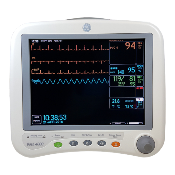
Charging Status Graph NBP Go/Stop Zero All Trim Knob Silence Alarm/ Admit Charging Status Power Graph Go/Stop NBP Go/Stop Zero All Silence Alarm/ Admit Dash 4000 001C 051D Dash 3000 Monitor Dash 4000 Monitor Revision A Dash 3000/4000 Patient Monitor 2000966-339... - Page 22 Battery Compartment— The battery packs are located in this compartment. The battery compartment may be a single plastic door or two silicone doors. 925A Dash 3000/4000 Patient Monitor Revision A 2000966-339...
- Page 23 For measurements in or near the heart we recommend connecting the monitor to the potential equalization system. Use the green and yellow potential equalization cable and connect it to this pin. Revision A Dash 3000/4000 Patient Monitor 2000966-339...
-
Page 24: User Interface
When AC power is present, this key toggles the operational mode of the monitor between normal operation and stand-by mode. In standby mode patient monitoring discontinues. Only the charging function continues and the charging status indicators operate as described below. Dash 3000/4000 Patient Monitor Revision A 2000966-339... - Page 25 Neither indicator illuminates when the monitor is operating from both batteries simultaneously (i.e., in a very low battery charge condition when both batteries are joined together in order to sustain operation of the monitor). Revision A Dash 3000/4000 Patient Monitor 2000966-339...
-
Page 26: Optional Rac 2A Module Housing
An optional remote display can be connected to the system for viewing on a larger monitor, or in a separate room. The optional remote display: Requires Dash Port 2 docking station. Requires Dash 3000/4000 software version 5 or later. Must be within 150 feet of the Dash monitor. Dash 3000/4000 Patient Monitor... -
Page 27: Optional Icg Module
The monitor, with its optional built-in Wireless LAN, functionally performs the same as a monitor connected directly to the optional Unity Network. It can be viewed at the central station and by other ® GEmonitors on the network (i.e. Dash 3000/4000, Eagle 4000, and ® Solar patient monitors). -
Page 28: Optional Remote Control
Trim Knob control, and allows the user to operate the patient monitor from across the room. Eighteen hard keys are configured for adult, neonatal, or operating room applications. 821A 2-10 Dash 3000/4000 Patient Monitor Revision A 2000966-339... -
Page 29: Software Packages And Software Options
(AMI) in women. The Unity Network option enables you to view other patients on the network, interface with a central station and other network devices, and perform Combo or Rover Combo monitoring. Revision A Dash 3000/4000 Patient Monitor 2-11 2000966-339... -
Page 30: Technical Specifications
Prioritized by parameter Controls Standard: Trim Knob control plus 5 hard keys: POWER, NBP GO/STOP, ZERO ALL, SILENCE ALARM/ADMIT, and GRAPH GO/STOP. Optional remote control Trim Knob control and 18 active hard keys. 2-12 Dash 3000/4000 Patient Monitor Revision A 2000966-339... -
Page 31: Ecg
5.0 Hz (-3 dB) to 25 Hz (-3 dB) Impulse Response: For an impulse of 3 mV applied for 100 ms: Displacement following impulse: < 0.1 mV Slope following impulse: < 0.3 mV/s Revision A Dash 3000/4000 Patient Monitor 2-13 2000966-339... - Page 32 ±2 mV to ±700 mV Input pulse width: 0.1 ms to 2 ms Rise time: 10 µs to 100 µs Over/under shoot: 2 mV (max) Baseline drift: <0.5 mV/hour with a ±700-mV, 2-ms pacemaker pulse applied 2-14 Dash 3000/4000 Patient Monitor Revision A 2000966-339...
-
Page 33: Invasive Blood Pressure (Bp)
10 to 220 mmHg Pediatric: 10 to 210 mmHg Neonatal: 10 to 110 mmHg Mean pressure range Adult: 20 to 260 mmHg Pediatric: 20 to 220 mmHg Neonatal: 20 to 125 mmHg Revision A Dash 3000/4000 Patient Monitor 2-15 2000966-339... - Page 34 Cuff sizes: Disposable: Large adult, adult, small adult, pediatric, small pediatric, and infant Reusable: Thigh, large adult, adult, child, and infant Alarms: User-selectable upper and lower limits for systolic, diastolic, and mean pressures 2-16 Dash 3000/4000 Patient Monitor Revision A 2000966-339...
-
Page 35: Ge Pulse Oximetry (Spo2)
25 to 240 bpm, ±3 bpm Pulse Rate, motion: 25 to 240 bpm, ±5 bpm Alarms: User-selectable upper and lower limits for SpO2 and PPR. Patents 5482036, 5490505, 5632272, 5685299, 5769785, 6002952, 6036642, 6067462, 5,758,644; 6206830; 6157850 Revision A Dash 3000/4000 Patient Monitor 2-17 2000966-339... -
Page 36: Cardiac Output (Co)
0.4 to 10 Ω variation Detection sensitivity: Accuracy: Respiration rate ±1 BrPM Waveform display bandwidth: 0.1 to 1.8 Hz (–3 dB) Alarms: User-selectable upper and lower respiration rate limits, and user-selectable apnea limit 2-18 Dash 3000/4000 Patient Monitor Revision A 2000966-339... -
Page 37: Temperature (Temp)
Patient interface: Compatible with Novametrix Medical Systems’ Capnogard monitoring product Airway adaptors Types: Adult reusable (standard), adult disposable, neonatal Dead space/chamber volumes: Adult reusable: <5 cc Adult disposable: <5 cc Neonatal: <0.5 cc Revision A Dash 3000/4000 Patient Monitor 2-19 2000966-339... - Page 38 ±1 breath per minute Resolution: ±1 breath per minute Barometric pressure sensor specifications: Range: 530 to 785 mmHg (70.7 to 104.7 kPa) Accuracy: ±25 mmHg Alarms: User-selectable upper and lower limits for CO2 and RR. 2-20 Dash 3000/4000 Patient Monitor Revision A 2000966-339...
-
Page 39: Analog Output
Maximum input voltage: ±30 V (with respect to ground on pin 3) Input impedance: 10 kΩ (min) for -25 V < VIN < 25 V Pulse width: 1.0 ms (min), VIN > 2.5 V Revision A Dash 3000/4000 Patient Monitor 2-21 2000966-339... -
Page 40: Battery
200 dots/in Number of waveform channels: Paper width: 50 mm (1.97 in) Paper length: 30 m (100 ft) Paper speed: 0.1, 0.5, 1, 5, 10, 12.5, 25, and 50 mm/sec (± 2%) 2-22 Dash 3000/4000 Patient Monitor Revision A 2000966-339... -
Page 41: Rf Wireless Lan
10° to 40° C (50° to 104°F) Relative humidity: 5 to 95% at 40°C Vibration: MIL-STD 810E, Method 514.4, Category 1 Altitude: -273.10 m to 2,942.84 m (-896 ft to 9655 ft) Revision A Dash 3000/4000 Patient Monitor 2-23 2000966-339... -
Page 42: Physical Specifications
29.26 cm (11.5 inches) Depth: Dash 3000 20 cm (8 inches) Dash 4000 24.26 cm (9.55 inches) Weight (without batteries) Dash 3000 5.08 kg (11.2 lbs) Dash 4000 5.53 kg (12.2 lbs) 2-24 Dash 3000/4000 Patient Monitor Revision A 2000966-339... -
Page 43: Certification
CE marking for Council Directive 93/42/EEC concerning medical devices Radio and Telecommunication Terminal Equipment Directive Electromagnetic Compatibility Compliance (EMC) The Dash 3000/4000 system meets the requirements of EN 60601-1-2 (1993–04) Medical Electrical Equipment, Part 1: General Requirements for Safety, 2. Collateral Standard: Electromagnetic compatibility—... - Page 44 2. This device must accept any interference received, including interference that may cause undesired operation. WARNING Changes or modifications not expressly approved by the party responsible for compliance could void the user’s authority to operate the equipment. 2-26 Dash 3000/4000 Patient Monitor Revision A 2000966-339...
-
Page 45: Installation
Installation Revision A Dash 3000/4000 Patient Monitor 2000966-339... - Page 46 For your notes Dash 3000/4000 Patient Monitor Revision A 2000966-339...
-
Page 47: Connections
The RAC 2A module housing connects to the monitor via a standard category 5 patch cable (PN 418335-002) which plugs into the Aux port on the monitor and to the Auto Port on the back of the RAC 2A module housing. Revision A Dash 3000/4000 Patient Monitor 2000966-339... - Page 48 The remote control is programmed for specific care areas (adult, neonatal, or operating room). NOTE The error message WARNING: REMOTE MISMATCHED WITH MONITORING MODE displays if a mismatched remote control is connected to the monitor. Dash 3000/4000 Patient Monitor Revision A 2000966-339...
- Page 49 Refer to the label on the back of the unit for the voltage and current requirements. line voltage selector: 115V for a 100-120V power source 230V for a 220-240V power source 115V 829A 004A Revision A Dash 3000/4000 Patient Monitor 2000966-339...
-
Page 50: Front Panel Indicators
Battery A and B Charge Status Indicators 009A 053A Dash 3000 Monitor’s Front Panel Dash 4000 Monitor’s Front Panel AC Power Indicator The indicator illuminates green when AC power is applied to the monitor. The indicator is not illuminated when the monitor is not powered. -
Page 51: Power Up
When all cables are properly connected, press the POWER button to turn the monitor on. All front panel indicators will illuminate until the power-up sequence is complete. After approximately 20 seconds you should see a display on the screen. Revision A Dash 3000/4000 Patient Monitor 2000966-339... -
Page 52: Optional Ethernet Communication
Installation: Optional Ethernet Communication Optional Ethernet Communication Overview Ethernet is a local area network used as the main link of the optional GE Unity Network, a comprehensive information communication system. The Unity Network offers the high rate of communication of 10 megabits per second. -
Page 53: Segment And Branch
This lowers the amount of data traffic passing between segments, and makes the network more efficient than a system that is connected with repeaters. Revision A Dash 3000/4000 Patient Monitor 2000966-339... -
Page 54: Twisted Pair Cabling (10Baset)
Wireless LAN communication with the Unity Network. Installation of the RF LAN (Wireless LAN) option. Configuration and verification of the monitor’s RF LAN operation. Activation of the RF LAN by disconnecting the monitor’s Ethernet cable. 3-10 Dash 3000/4000 Patient Monitor Revision A 2000966-339... -
Page 55: Maintenance
Maintenance Revision A Dash 3000/4000 Patient Monitor 2000966-339... - Page 56 For your notes Dash 3000/4000 Patient Monitor Revision A 2000966-339...
-
Page 57: Maintenance Schedule
12 months thereafter, and each time the unit is serviced. Clearing the Stored Patient Data Memory—Admit and discharge a test patient every 12 months to clear the monitor’s stored patient data memory. Revision A Dash 3000/4000 Patient Monitor 2000966-339... -
Page 58: Visual Inspection
Physical damage to a flat panel display glass may pose an implosion hazard. Have the flat panel display replaced by qualified service personnel if necessary. Safety labels and inscription on the device are clearly legible. Dash 3000/4000 Patient Monitor Revision A 2000966-339... -
Page 59: Cleaning
Wring the excess solution from the cloth. Do not drip any liquid into open vents, switches, plugs, or connectors. Dry the surfaces with a clean lint-free cloth. Revision A Dash 3000/4000 Patient Monitor 2000966-339... -
Page 60: Cleaning The Print Head
Continue wiping until the cloth/swab wipes clean. 6. Wipe paper drive roller clean of any bits of paper and debris with alcohol and a nonabrasive material. Dash 3000/4000 Patient Monitor Revision A 2000966-339... -
Page 61: Battery Power
The liquid is caustic to eyes and skin. If the liquid comes into contact with eyes or skin, flush with clean water and seek medical attention. NOTE: For optimal performance and safety, use only batteries supplied by GE. Revision A Dash 3000/4000 Patient Monitor 2000966-339... - Page 62 Battery indicators let you know when the monitor is using battery power. 634B Monitor with Battery Packs WARNING Make sure the batteries are completely inserted and that the battery door is securely latched. Falling batteries could seriously or fatally injure a neonatal patient. Dash 3000/4000 Patient Monitor Revision A 2000966-339...
-
Page 63: Battery Indicators
Charge Status Indicators Battery Power Indicator Battery Power Indicator Charge Status Indicators Dash 3000 Monitor’s Control Panel Dash 4000 Monitor’s Control Panel Battery Power Indicator The indicator illuminates yellow when the monitor is battery powered. The indicator is not illuminated when the monitor is not powered or when AC power is applied. - Page 64 The solid portion represents the Full Charge Capacity of the battery as a percentage of its Design Capacity. 809A Battery Capacity Gauges Location of Battery Capacity Gauges on the Monitor 4-10 Dash 3000/4000 Patient Monitor Revision A 2000966-339...
-
Page 65: Lithium-Ion Battery
The Cadex SMart Two+ charger charges one battery in less than 4 hours and two batteries in less than 8 hours. When two batteries are used, the charger applies half of the charging current to each battery. Revision A Dash 3000/4000 Patient Monitor 4-11 2000966-339... -
Page 66: How To Identify The Battery Charge Capacity
AC power source and is not powered by battery on a regular basis, the life of the battery may be less than 12 months. GE recommends that you remove the battery and store it near the monitor until it is needed for transport. - Page 67 The dotted portion of the icon outline shows that the battery has lost 20% of its Design Capacity. The solid-outline portion is half filled in, showing that the battery is charged to only 50% of available capacity. Full Charge Capacity 859A 50% Available Capacity Revision A Dash 3000/4000 Patient Monitor 4-13 2000966-339...
- Page 68 If a battery is not present, a NO BATT message is displayed in this column. If the battery is NO COMM (communication with this battery has failed), “unknown” is displayed for all rows except the SLOT STATUS row. 4-14 Dash 3000/4000 Patient Monitor Revision A 2000966-339...
- Page 69 As a battery ages, its maximum charge level becomes a smaller percentage of its Design Capacity. The solid portion represents the current charge level of the battery as a percentage of its maximum Full Charge Capacity. Revision A Dash 3000/4000 Patient Monitor 4-15 2000966-339...
- Page 70 10 minutes per battery run time remaining. The monitor will issue a System Warning alarm when shutdown is imminent (less than one minute left of remaining run time). 4-16 Dash 3000/4000 Patient Monitor Revision A 2000966-339...
-
Page 71: Battery Maintenance
Inside a monitor that is connected to an AC power source. NOTE To extend the life of the battery, GE recommends that you charge the battery using the external Cadex SMart Two+ charger. Charging the Battery With a Cadex SMart Two+ Charger 1. - Page 72 BATTERY LOW message, or until the monitor shuts down. 8. Re-connect the monitor to the AC power source. Allow the battery to fully charge to complete the conditioning cycle. 4-18 Dash 3000/4000 Patient Monitor Revision A 2000966-339...
-
Page 73: How To Store The Battery
Watch the battery charger LEDs. The RUN LED should stop flashing and remain illuminated for approximately one minute later the CONDITION LED should stop flashing. At this time, the battery is awake and being charged. Revision A Dash 3000/4000 Patient Monitor 4-19 2000966-339... - Page 74 7. Quickly reboot (or power cycle) the monitor to begin charging the batteries. The monitor’s illuminated yellow-colored CHARGING STATUS LED indicates that the battery is being charged. NOTE The monitor will not charge the battery while it is running the Boot Loader program. 4-20 Dash 3000/4000 Patient Monitor Revision A 2000966-339...
-
Page 75: How To Replace The Batteries
5. Verify that the monitor operates correctly. a. Confirm that the Battery IDs with a battery icon displays in the lower right corner of the monitor. b. Verify that the Battery LEDS illuminate either green or amber. Revision A Dash 3000/4000 Patient Monitor 4-21 2000966-339... - Page 76 In the United States and Canada, the Rechargeable Battery Recycling Corporation (RBRC) can help you locate your nearest rechargeable battery collection site. You can contact RBRC by telephone or by accessing their internet web site. telephone: 1-800-8-BATTERY (800-822-88379) internet address: www.rbrc.org 4-22 Dash 3000/4000 Patient Monitor Revision A 2000966-339...
-
Page 77: The Cadex Smart Two+ Charger
FAIL and CONDITION Conditioning is complete — fail target. Equipment Software Requirements The monitor must use Dash 3000/4000 software version 2A or later. The Cadex SMart Two+ Charger must use software version 1.1 or later. Revision A Dash 3000/4000 Patient Monitor... -
Page 78: Electrical Safety Tests
Electrical safety tests provide a method of determining if potential electrical health hazards to the patient or operator of the device exist. Recommendations GE recommends that you perform all safety tests presented in this chapter. upon receipt of the device (monitor and its associated equipment),... -
Page 79: Power Outlet Test
ECG Test Body All leads together Masimo SET SPO2 Test Body 2006036-001 GE and Nellcor SPO2 Test Body 2006646-001 Power Outlet Test Before starting the tests, the power outlet from which the monitoring device will get electrical power must be checked. This test checks the condition of the power outlet to ensure correct results from leakage tests. -
Page 80: Ground (Earth) Integrity
This test normally is only required as a manufacturing production test to receive safety agency compliance (i.e. IEC601-1). Some country agency's do require this test after field equipment repairs (i.e. Germany's DIN VDE 0751 standards). Consult your country/local safety agency if in question. 4-26 Dash 3000/4000 Patient Monitor Revision A 2000966-339... - Page 81 0.2 ohms. When taking this measurement, move the unit's power cord around. There should be no fluctuations in resistance. Revision A Dash 3000/4000 Patient Monitor 4-27 2000966-339...
-
Page 82: Ground (Earth) Wire Leakage Current Tests
7. Read the current leakage indicated on DMM. NOTE If either reading is greater than the appropriate specification below, the device under test fails. Contact GE Medical Systems Information Technologies Technical Support. 300 µA (0.3 volts on the DMM), and the device under test is powered from 100-120 V/50-60 Hz 300 µA (0.3 volts on the DMM), and the device under test is... -
Page 83: Enclosure Leakage Current Test
6. Read the current leakage indicated on DMM. NOTE If either reading is greater than the appropriate specification below, the device under test fails. Contact GE Medical Systems Information Technologies Technical Support. • 300 µA (0.3 volts on the DMM), and the device under test is powered from 100-120 V/50-60 Hz •... -
Page 84: Patient (Source) Leakage Current Test
6. Read the leakage current indicated on the DMM. NOTE If either reading is greater than 50 µA (0.05 volts on the DMM), the device fails this test. Contact GE Medical Systems Information Technologies Technical Support. 4-30 Dash 3000/4000 Patient Monitor... -
Page 85: Patient (Sink) Leakage Current Test (Mains Voltage On The Applied Part)
The AAMI and IEC single fault condition (ground open) is 50 µA, whereas the normal condition (ground closed) is less. 12. Repeat the steps in this procedure using the appropriate GE or Masimo SET SPO2 Test Body. Connect the SPO2 Test Body to the blue SPO2 connector of the device under test. -
Page 86: Test Completion
ES-1 standard requires using the patient cable. 1. Set the power switch on the device to OFF. 2. Repeat the steps in this procedure using the appropriate GE or Masimo SET SPO2 Test Body. Connect the SPO2 Test Body to the... -
Page 87: Checkout Procedures
The checkout procedures are written for the test equipment in the following table. If you use test equipment other than those GE recommends, you may need to slightly modify some test steps. - Page 88 NBP Cuff Coupling (400787-001) NBP Hose Coupling (46100-002) NBP Tee (4745-101) NBP Tubing 2 feet (401582-001) Manometer: digital (Sensym PDM200M), mercury, or equivalent NBP Tube (414873-001) NBP Cuff (9461-301) Pipe: PVC DEFIB Sync Test Oscilloscope 4-34 Dash 3000/4000 Patient Monitor Revision A 2000966-339...
-
Page 89: Monitor Power-Up Tests
If the AC LED stays on, but the screen is blank, the monitor is likely in “standby mode” (battery charging). Press the POWER button to enter the normal mode. If the AC indicator is on, continue with the tests. Revision A Dash 3000/4000 Patient Monitor 4-35 2000966-339... - Page 90 (batteries must have more than 10% charge). Pull that battery out and verify the other LED lights, thus indicating the unit is powered by the other battery. Reinstall battery and plug in monitor (or the docking station). 4-36 Dash 3000/4000 Patient Monitor Revision A 2000966-339...
-
Page 91: Ecg Tests
Wave (QRS complex). 5. Verify all six ECG leads are available to view and are noise-free. 6. Select DETECT PACE and set to PACE 2. 7. Select a pacemaker pulse on the simulator. Revision A Dash 3000/4000 Patient Monitor 4-37 2000966-339... - Page 92 15. Observe that the calibration pulse properly displays and graphs. 016A 16. This completes the 5 Lead ECG test. Continue to the next steps of these checkout procedures. 4-38 Dash 3000/4000 Patient Monitor Revision A 2000966-339...
- Page 93 MUSE system. If no MUSE system is connected, an error message appears on the bottom of the monitor’s display. 8. Delete this test 12SL ECG from the MUSE system’s edit list. Revision A Dash 3000/4000 Patient Monitor 4-39 2000966-339...
-
Page 94: Respiration Tests
30 ±2 (respirations per minute), RESP waveform appears distortion-free on the monitor. 6. Disconnect the ECG patient cable from the ECG/RESP connector of the monitor. Proceed to the next steps in these checkout procedures. 4-40 Dash 3000/4000 Patient Monitor Revision A 2000966-339... -
Page 95: Temperature Tests
7. Verify a T2 reading of 37.0° ±0.4° C in the TEMP parameter window on the monitor display. 8. Repeat the above procedure using 700 settings on simulator and cable. 9. Remove the temperature adaptor and temperature simulator cable from the monitor and patient simulator. Revision A Dash 3000/4000 Patient Monitor 4-41 2000966-339... -
Page 96: Cardiac Output Tests
35.8 – 36.2 37.0°C 36.8 – 37.2 41.7°C 41.5 – 41.9 4. Verify a CO parameter window appears on the monitor display with correct BT readings as shown in the table above. 4-42 Dash 3000/4000 Patient Monitor Revision A 2000966-339... - Page 97 37°C at 5 liters of blood per minute ± 5%. 9. Repeat this test with the adapter set to 24° and the COMPUTATIONAL CONSTANT: set to 0.595. 10. The output should be the same. Revision A Dash 3000/4000 Patient Monitor 4-43 2000966-339...
-
Page 98: Invasive Blood Pressure Tests
BP1 connector on monitor blood pressure simulator cable, PN 700095-001 patient simulator 863A To Connect to the BP2 Connector BP2 connector on monitor blood pressure simulator cable, PN 700095-001 patient simulator 864A 4-44 Dash 3000/4000 Patient Monitor Revision A 2000966-339... - Page 99 3. Press the ZERO ALL (FUNCTION) key on the front panel of the monitor to zero-reference the BP waveform. 4. Change the patient simulator BP output to 200 mmHg (240 if using the Marq II or MarqIII). Revision A Dash 3000/4000 Patient Monitor 4-45 2000966-339...
- Page 100 120/80 (93) in the BP parameter window on the monitor display. 8. Disconnect the BP simulator cable from the BP connector of the monitor. 9. Complete steps for each enabled BP connector. 10. This completes the BP tests. 4-46 Dash 3000/4000 Patient Monitor Revision A 2000966-339...
-
Page 101: Pulse Oximetry Tests For Ge Spo2 Oximeter
Maintenance: Checkout Procedures Pulse Oximetry Tests for GE SPO2 Oximeter 1. Set the pulse oximetry (SpO ) simulator power switch to the OFF position. 2. Connect the Nellcor-style SpO simulator cable between the SpO connector of the monitor and the SpO simulator. - Page 102 9. Make sure the monitor still displays an SpO value between 97 and 100% (97 and 102%), or an interference detection message is displayed. 10. Turn the simulator OFF. 11. Disconnect the simulator cable from the device under test. 4-48 Dash 3000/4000 Patient Monitor Revision A 2000966-339...
-
Page 103: Pulse Oximetry Tests For Masimo Set Spo2
5. Make sure the SPO2 % value on the monitor flashes, and it sounds an alarm. 6. Return the low limit to the original value. 7. Disconnect the simulator cable from the module. Revision A Dash 3000/4000 Patient Monitor 4-49 2000966-339... -
Page 104: Noninvasive Blood Pressure Tests
(e.g. July 4 = 0407). 3. Select CALIBRATE > CALIBRATE NBP > CHECK CAL OFF > START. The text on the menu item changes from CHECK CAL OFF to CHECK CAL IN PROGRESS. 4-50 Dash 3000/4000 Patient Monitor Revision A 2000966-339... - Page 105 The pneumatic control circuit of the monitor vents air pressure in the pneumatic circuit of the monitor to atmosphere and causes the NBP cuff to deflate. 5. Remove the NBP test setup apparatus from the monitor. The NBP tests are complete. Revision A Dash 3000/4000 Patient Monitor 4-51 2000966-339...
-
Page 106: Analog Output And Defibrillator Synchronization Tests
SYNC connector. They should closely resemble the waveforms in the figures below. DEFIB Sync Connector: ECG Signal Pin:—7 Ground Pin:—3 Probe Type:—x10 Time/Division:—0.2S Volts/Division:—0.5V 023A DEFIB Sync Connector: Arterial BP Signal Pin:—6 Ground Pin:—5 Probe Type:—x10 Time/Division:—0.2S Volts/Division:—0.2V 024A 4-52 Dash 3000/4000 Patient Monitor Revision A 2000966-339... - Page 107 5V and a pulse width of 10ms. DEFIB Sync Connector: Marker Out (Frequency) Signal Pin:—1 Ground Pin:—4 Probe Type:—x10 Time/Division:—0.2S Volts/Division:—1V 025A DEFIB Sync Connector: Marker Out (Pulse Width) Signal Pin:—1 Ground Pin:—4 Probe Type:—x10 Time/Division:—5mS Volts/Division:—1V 026A Revision A Dash 3000/4000 Patient Monitor 4-53 2000966-339...
-
Page 108: End-Tidal Co 2 Test
Test To verify the mainstream end-tidal CO2, refer to the CO2 chapter in the Dash 3000/4000 Patient Monitor Operator’s Manual. This test requires you perform a zero and reference check by using the sample cells provided on the end-tidal CO2 cable. -
Page 109: Battery Tests
(e.g. July 4 = 0407). 3. Select GRAPH TEST PATTERN > START. 4. Verify the following: Fonts. Shading. Triangle Pattern. No missing dots. Select GRAPH TEST PATTERN > STOP. Revision A Dash 3000/4000 Patient Monitor 4-55 2000966-339... -
Page 110: Graph Speed Test
2. Verify the speaker volume of the monitor changes accordingly. 3. Return the volume of the monitor to the level it was previously set to, before you changed it for this test. 4-56 Dash 3000/4000 Patient Monitor Revision A 2000966-339... -
Page 111: Network Test
1. If the monitor has the Wireless LAN, disconnect the Ethernet cable and verify Wireless LAN communication still exist between beds, 2. Reconnect the Ethernet Cable. 3. Return to the Main Menu. Revision A Dash 3000/4000 Patient Monitor 4-57 2000966-339... -
Page 112: Dash Port Docking Station Test
2. Ground (earth) Continuity Test, 3. Ground (earth) Wire Leakage Tests, and 4. Enclosure Leakage Current Test. Operation Complete the “Maintenance Schedule” procedures found in the “RAC 2A Module Housing Service Manual.” 4-58 Dash 3000/4000 Patient Monitor Revision A 2000966-339... -
Page 113: Peripheral Or External Devices
2. Set all test equipment power switches to the off position. 3. Unplug the monitor (or docking station) from AC power. 4. Remove all test equipment from the monitor (or docking station). Revision A Dash 3000/4000 Patient Monitor 4-59 2000966-339... -
Page 114: Maintenance Checklist
BP analog output Mainstream End-tidal CO Sidestream End-tidal CO “Electrical Safety Tests” on page 4-24 Power outlet Ground (earth) integrity Ground (earth) wire leakage Enclosure leakage test ECG Patient (source) leakage current test 4-60 Dash 3000/4000 Patient Monitor Revision A 2000966-339... -
Page 115: Checkout Procedures
Patient (sink) leakage current (mains voltage on the applied part) “Checkout Procedures” on page 4-33 Power-up Respiration Temperature Cardiac output Invasive blood pressure Pulse oximetry for GE SpO oximeter Pulse oximetry for Masimo SpO oximeter Non-invasive blood pressure Analog output and defibrillator synchronization End-tidal CO Battery Graph... -
Page 116: Repair Log
Maintenance: Maintenance Checklist Repair Log Unit Serial Number: Institution Name: Date Maintenance/Repair Technician 4-62 Dash 3000/4000 Patient Monitor Revision A 2000966-339... -
Page 117: Troubleshooting
Troubleshooting Revision A Dash 3000/4000 Patient Monitor 2000966-339... - Page 118 For your notes Dash 3000/4000 Patient Monitor Revision A 2000966-339...
-
Page 119: Service Menus
1. Hold down NBP GO/STOP and ZERO ALL (FUNCTION) on the front panel. 2. Press and release the Trim Knob control. 3. Keep holding NBP GO/STOP and ZERO ALL (FUNCTION) until the Boot Loader information appears on the display. Revision A Dash 3000/4000 Patient Monitor 2000966-339... - Page 120 A unique password is required for each option. Contact your sales/service representative to obtain a password. You must provide your product serial number and Ethernet address. (The Ethernet address is displayed in the Boot Code banner information.) Dash 3000/4000 Patient Monitor Revision A 2000966-339...
-
Page 121: Main Menu Service Mode Menu
Internet address for use on the network; and enter or change the time and date on the monitor. Do NOT use ANY of these options unless specifically instructed to do so. Revision A Dash 3000/4000 Patient Monitor 2000966-339... - Page 122 Because of this, unnecessary tampering with service mode menu option items for experimentation purposes is not recommended by GE and may cause a malfunction of the monitor. Service Mode Menu Option Items Following is a list of options in the main code service menu.
- Page 123 (IP) address. An incorrect internet address may also prevent the monitor from viewing other monitors on the network even though the unit names match. Whether or not this can occur depends on the network topology at the installed site. Revision A Dash 3000/4000 Patient Monitor 2000966-339...
- Page 124 (Refer to Chapter 6, “Configuration” for detailed procedures.) WARNING Loss of patient history. This menu should rarely be used because patient histories will be lost. Dash 3000/4000 Patient Monitor Revision A 2000966-339...
-
Page 125: Review Errors
Troubleshooting: Service Menus Review Errors The Review Errors menu is an advanced troubleshooting tool used by GE engineering personnel. Some of the information recorded in the monitor error log can be useful for field service troubleshooting. About the Monitor Error Log This section provides an introduction to error log usage and meaning. -
Page 126: Error Log Information
TIME The time the event or problem occurred. ERROR NUMBER A sequential number used to identify each event or problem. INPUT ERROR Additional information used to determine the cause of the error. 5-10 Dash 3000/4000 Patient Monitor Revision A 2000966-339... -
Page 127: Error Logs
FORCED RESET The operating system restarted normally after a known condition, such as an Internet address change, patient discharge, etc. Revision A Dash 3000/4000 Patient Monitor 5-11 2000966-339... -
Page 128: Battery Alarms And Messages
A serious failure has occurred while using or charging the battery. CHECK BATT STATUS System MESSAGE Charger Failure Charger communications have failed. NOTE INTERNAL CHARGER FAILED, CALL SERVICE also appears in the Battery Status information window. 5-12 Dash 3000/4000 Patient Monitor Revision A 2000966-339... -
Page 129: Battery Messages Displayed In The Battery Status Information Window
If the battery is asleep and you need to “wake up” the battery, see “How to Wake Up the Battery” on page 4-19. If the battery will not “wake up” it is probably faulty and should be replaced. Revision A Dash 3000/4000 Patient Monitor 5-13 2000966-339... -
Page 130: Power Source Tests
Line to neutral: 120 VAC Line to ground: 120 VAC Neutral to ground: < 3 VAC Readings other than these indicate improper wiring. Have the wall receptacle checked by an electrician. 5-14 Dash 3000/4000 Patient Monitor Revision A 2000966-339... -
Page 131: Power Cord And Plug
Verify line, neutral, and ground conductors are properly connected to the power cord plug and are not short-circuited. Rewire and tighten these, or replace the power cord, as necessary. Revision A Dash 3000/4000 Patient Monitor 5-15 2000966-339... -
Page 132: Data Acquisition Tests
WAVEFORM 2 WAVEFORM 3 WAVEFORM 4 LEAD II LEAD V LEAD I LEAD III d. Press the GRAPH GO/STOP front panel control on the monitor to start and stop a manual graph. 5-16 Dash 3000/4000 Patient Monitor Revision A 2000966-339... - Page 133 3. Test the patient simulator and ECG patient cables on a working monitor to verify the ECG signal. 4. If the ECG signal, patient simulator and ECG patient cables are good, the acquisition PCB is suspect and you need to replace it. Revision A Dash 3000/4000 Patient Monitor 5-17 2000966-339...
-
Page 134: Lead Fail Functions
80 bpm. Verify the pacemaker spikes display at the same amplitude. 7. Disable the pacemaker detection function of the monitor. Verify the displayed pacemaker spikes have a different amplitude than in the previous step. 5-18 Dash 3000/4000 Patient Monitor Revision A 2000966-339... -
Page 135: Invasive Blood Pressure Functions
BP patient connector on the side panel of the monitor. Zero-Reference Enabled BP Input Properly zero-reference each enabled BP input. 1. Set the patient simulator BP output to 0 mmHg 2. Press the ZERO ALL (FUNCTION) key on the monitor. Revision A Dash 3000/4000 Patient Monitor 5-19 2000966-339... - Page 136 (±2% or 1 mmHg, whichever is greater) is how the parameter values listed above, were derived. Use of any other manufacturer patient simulator, and associated specifications, can potentially change these test results. 5-20 Dash 3000/4000 Patient Monitor Revision A 2000966-339...
- Page 137 If any pins are bent or broken, replace the DAS assembly. 3. Inspect the dual BP cable connectors on the monitor for bent or broken pins. If any pins are bent or broken, replace the DAS assembly. Revision A Dash 3000/4000 Patient Monitor 5-21 2000966-339...
-
Page 138: Respiration Functions
Respiration waveform is displayed and noise-free. Markers appear in the displayed respiration waveform (see figure below). These indicate the points at which the monitor senses inspiration and expiration for determination of the respiration rate. 582A 5-22 Dash 3000/4000 Patient Monitor Revision A 2000966-339... - Page 139 583A NOTE With patients that exhibit excessively high baseline chest impedance, proper respiration monitoring can be extremely difficult, if not impossible. Revision A Dash 3000/4000 Patient Monitor 5-23 2000966-339...
-
Page 140: Noninvasive Blood Pressure Functions
If it is set to a neonatal ICU when the monitor is used for the adult ICU application or vice versa, problems listed to the left may occur. 5-24 Dash 3000/4000 Patient Monitor Revision A 2000966-339... -
Page 141: Wireless Lan Troubleshooting
If the code does not match: a. Check to make sure the correct Access Point is installed. b. Refer to the Wireless LAN (Symbol Access Point) Installation and Service Manual for details on proper Access Point installation. Revision A Dash 3000/4000 Patient Monitor 5-25 2000966-339... - Page 142 RF interference. If the monitor is out of range, add additional Access Points to extend the coverage area. If there is RF interference, the source of the interference must be removed or shielded. 5-26 Dash 3000/4000 Patient Monitor Revision A 2000966-339...
-
Page 143: Service Tips
Missing segments in the graph data. Print head may be dirty or Clean the printhead. Refer to Chapter 4, “Maintenance” defective. Perform a graph test. If problem persists, replace the writer assembly. Revision A Dash 3000/4000 Patient Monitor 5-27 2000966-339... - Page 144 Replace the remote control with a known good one. Masimo SET SPO2 Probe or module malfunction Five or more consecutive hardware Review the input error log for Masimo failure codes. failures have occurred. 5-28 Dash 3000/4000 Patient Monitor Revision A 2000966-339...
-
Page 145: Acquisition Pcb Symptoms
PCB failure. All of these are functions controlled by microcontroller or graphics processing circuitry located on the Processor/Power Management PCB. Revision A Dash 3000/4000 Patient Monitor 5-29 2000966-339... -
Page 146: Error Messages
“WARNING: The EEPROM data was found to be either INVALID or Following the EEPROM dump, restore data: uninitialized. GE factory defaults will be stored in both the EEPROM 1. Restore Ethernet address and IP address as requested by and the monitor’s configuration memory. You will be required to re- the Boot Code. - Page 147 These messages are displayed while the monitor monitor to monitor the patient. powers up. Once the “Internal lithium battery is 3. Contact GE Service for lithium battery replacement LOW” message appears, the monitor will complete instructions. all the power-up tests. Then, after the last test is...
-
Page 148: Language-Specific Information
Text for alarm broadcast over the optional network is in English. All text input is in English only (i.e., text for unit name, bed name, patient information, and custom default name). 5-32 Dash 3000/4000 Patient Monitor Revision A 2000966-339... -
Page 149: Configuration
Configuration Revision A Dash 3000/4000 Patient Monitor 2000966-339... - Page 150 For your notes Dash 3000/4000 Patient Monitor Revision A 2000966-339...
-
Page 151: Configuring A Monitor
(telemetry) monitoring or both. know if the monitor will be moved from one Ethernet connection to another. Revision A Dash 3000/4000 Patient Monitor 2000966-339... - Page 152 MUSE Protocol Transcutaneous Pace Blank Length Country Selection Configure Wireless LAN Set Language AFIB Identification IntelliRate Analog Out Buzz After completing all necessary procedures, perform the “Checkout Procedure” found in Chapter 4, Maintenance. Dash 3000/4000 Patient Monitor Revision A 2000966-339...
-
Page 153: Main Menu Selections
041A 4. Use the Trim Knob control to select and change each character. Up to five characters may be entered. 5. Select SET BED NUMBER and press the Trim Knob control to exit. Revision A Dash 3000/4000 Patient Monitor 2000966-339... -
Page 154: Patient-Monitor Type
4. Rotate Trim Knob control to select the type of environment the monitor will be used in. 5. Press Trim Knob control to exit. Your selection displays at the top of the screen after the time. Dash 3000/4000 Patient Monitor Revision A 2000966-339... -
Page 155: Set Graph Locations
Check the programmed alarms and manual graph locations at the monitor. Ensure the care unit name is the same in the monitor and in the central station. Ensure the internet protocol (IP) addresses are programmed correctly. Revision A Dash 3000/4000 Patient Monitor 2000966-339... -
Page 156: Admit Menu
(e.g. July 4 = 0407) 3. Select MENU SETUP > ADMIT MENU. ↑ ↓ 513A 4. Use the Trim Knob control to select the function of the monitor. 5. Press Trim Knob control to exit. Dash 3000/4000 Patient Monitor Revision A 2000966-339... -
Page 157: Boot Code Selections
4. Select Line Frequency then choose 50 Hz or 60 Hz line frequency. 5. Select Exit and wait for the monitor to display the message, “Writing settings to EEPROM...” 6. Manually reboot the monitor to implement this change. Revision A Dash 3000/4000 Patient Monitor 2000966-339... -
Page 158: Set Cic And Qs Protocol
Service Mode menu to set up the MUSE system’s Location ID and Site Number. Refer to “Access the Service Mode” page 5-5 and to “MONITOR SETTINGS” on page 5-7. 6-10 Dash 3000/4000 Patient Monitor Revision A 2000966-339... -
Page 159: Transcutaneous Pace Blank Length
Transcutaneous Pace Blank Length This menu option is reserved for future use and should not be changed. Set Country Selection Select DEFAULT or FRANCE to choose a particular set of GE factory defaults. 1. Activate the Boot Code. a. Hold down NBP GO/STOP and ZERO ALL. -
Page 160: Set Language
5. Select enabled to activate this option, or disabled to deactivate this option. 6. Select Exit and wait for the monitor to display the message, “Writing settings to EEPROM...” 7. Manually reboot the monitor to implement this change. 6-12 Dash 3000/4000 Patient Monitor Revision A 2000966-339... -
Page 161: Enable/Disable Intellirate
Verify that ECG INTELLIRATE is listed under “ENABLED SOFTWARE OPTIONS.” ® 9. Refer to the Patient Monitoring Addendum for the DASH 3000/4000 Operator’s Manual to configure the monitor to use this feature. Revision A Dash 3000/4000 Patient Monitor 6-13 2000966-339... -
Page 162: Analog Out Buzz
EEPROM...” 7. Manually reboot the monitor to implement this change. Completion The monitor is now ready for normal operation. At this time, perform the “Checkout Procedure” found in Chapter 4, Maintenance. 6-14 Dash 3000/4000 Patient Monitor Revision A 2000966-339... -
Page 163: Advanced User Procedures
3. Select SET TIME and use the Trim Knob control to change the time. The time displays as a 24-hour military clock. 4. Select SET DATE and use the Trim Knob control to change the date. Revision A Dash 3000/4000 Patient Monitor 6-15 2000966-339... -
Page 164: Transfer Monitor Defaults
1. At the server monitor, set up the monitor defaults you want to store. Refer to the following sections of the “Dash 3000/4000 Patient Monitor Operator’s Manual” for reference: Defaults Worksheet located in the preface of the manual. These are blank and allow you to enter your own default settings. - Page 165 If another set of defaults is desired, the user must manually select it from the Recall Defaults menu. After copying monitor defaults from another bed (the server monitor), verify that the defaults were transferred and arrhythmia levels are as desired. Revision A Dash 3000/4000 Patient Monitor 6-17 2000966-339...
- Page 166 SOFTWARE FEATURE LEVEL different software levels (i.e. Basic, Cardiac, MISMATCH Cardiopulmonary). ERROR COPYING UNIT DEFAULTS - The server and client monitors are set to COUNTRY CODE MISMATCH different country codes (i.e. DEFAULT or FRANCE). 6-18 Dash 3000/4000 Patient Monitor Revision A 2000966-339...
-
Page 167: Change Ethernet Address
Unity Network software option is enabled, the error logs may also be transferred over the network to a central station and copied onto diskette for further review or sent to GE personnel for review. The transferring procedure “Copying Error Log Files” is described later in this chapter. - Page 168 The name of the software task that was operating when the event/ problem occurred. Error Code The error log contains more than just operating system errors. Many events that have an impact upon the system are also entered into the log. 6-20 Dash 3000/4000 Patient Monitor Revision A 2000966-339...
- Page 169 Forced Restart—the system was restarted by a known condition (internet address change, video test, etc). Date and Time The date and time the event/problem occurred. Error Number A sequential number that is used to identify each event/problem. Revision A Dash 3000/4000 Patient Monitor 6-21 2000966-339...
-
Page 170: Transferring Error Logs
A Centralscope or CIC central station can perform normal patient data display tasks and act as a remote terminal. The remote terminal function is useful for retrieving, viewing, and saving error logs from any GE patient monitoring equipment communicating on the Unity Network. -
Page 171: Select The Monitoring Device
Using the Trim Knob control, change the error log date. Note that one of the selections is ALL, which retrieves all stored error logs from the specified device. When the desired date displays, press the Trim Knob control. 046A Revision A Dash 3000/4000 Patient Monitor 6-23 2000966-339... -
Page 172: Copy Error Logs
047A Once the copy function begins the Start Copy button changes to show the function: “copying.” Eject Floppy Select this option to eject the floppy diskette from the central station’s disk drive. 6-24 Dash 3000/4000 Patient Monitor Revision A 2000966-339... -
Page 173: Calibration
Calibration Revision A Dash 3000/4000 Patient Monitor 2000966-339... - Page 174 For your notes Dash 3000/4000 Patient Monitor Revision A 2000966-339...
-
Page 175: Hardware Calibration
Processor PCB DAS PCB Power Supply PCB Display - color Writer Assembly These adjustments are set and sealed during manufacture of the component or assembly. Breaking the seal of the adjustments voids the calibration. Revision A Dash 3000/4000 Patient Monitor 2000966-339... -
Page 176: Nbp Calibration
Unterminated defib sync cable, Manometer (Sensym PDM200M or mercury manometer), NBP tube, pn 9461-203, NBP cuff, pn 9461-301 (any size works), and Something to wrap the NBP cuff around (PVC pipe or coffee can). Dash 3000/4000 Patient Monitor Revision A 2000966-339... - Page 177 Checkout Procedure, Chapter 4, Maintenance. 1. Connect a cuff and manometer to the monitor. 2. Turn the digital manometer on and adjust the range switch to 1000 mmHg. 3. Select CAL GAIN OFF-> CAL GAIN OFF-> START. Revision A Dash 3000/4000 Patient Monitor 2000966-339...
- Page 178 (± 1 mmHg) for AT LEAST one full minute. 028B 9. Select CHECK CAL IN PROGRESS -> STOP. The monitor automatically releases pneumatic pressure in the entire plumbing circuit. Dash 3000/4000 Patient Monitor Revision A 2000966-339...
-
Page 179: Ecg Or Bp Calibration
(If ECG: Pin 7 = ECG signal, Pin 3 = ground. If BP: Pin 6 = BP, Pin 5 = ground.). 022A 3. Access the monitor’s Service Mode 4. Calibrate the ECG or the BP parameters. Revision A Dash 3000/4000 Patient Monitor 2000966-339... -
Page 180: End-Tidal Co Calibration
Calibration To calibrate the mainstream end-tidal CO , refer to the CO chapter in the Dash 3000/4000 Patient Monitor Operator’s Manual. To calibrate the sidestream end-tidal CO , refer to the documentation that came with the module. Dash 3000/4000 Patient Monitor... -
Page 181: Field Replaceable Units And Upgrades
DAS assembly. NOTE The instructions in this chapter only support monitors with the DSH product code. For monitors with the AAB product code, refer to the Dash 3000/4000 service manual, PN 2000966-270B. Revision A Dash 3000/4000 Patient Monitor 2000966-339... - Page 182 For your notes Dash 3000/4000 Patient Monitor Revision A 2000966-339...
-
Page 183: Disassembly Guidelines
NOTE GE recommends that you assemble the monitor using the NEW fasteners (screws, washers, etc.) provided in the Dash 3K/4K Hardware Kit FRU. Some fasteners, like the screws with a thread locking coating, are NOT intended to be re-used more than three times. -
Page 184: Hardware Assemblies
Handle all PCB assemblies by their edges. DO NOT flex or twist the circuit board. These guidelines may not guaranty a 100% static-free workstation, but can greatly reduce the potential for failure of any electrical/electronic assemblies being serviced. Dash 3000/4000 Patient Monitor Revision A 2000966-339... -
Page 185: After Reassembly
4-44. “Pulse Oximetry Tests for GE SPO2 Oximeter” on page 4-47. Use this procedure if you installed a GE DAS assembly. “Pulse Oximetry Tests for Masimo SET SPO2” on page 4-49. Use this procdure if you installed a Masimo DAS assembly. - Page 186 “RF LAN Test (option)” on page 4-57. “RAC 2A Module Housing Peripheral Device Test” on page 4-58. Writer None “Monitor Power-up Tests” on page 4- (Recorder) “Graph Test” on page 4-55. “Graph Speed Test” on page 4-56. Dash 3000/4000 Patient Monitor Revision A 2000966-339...
-
Page 187: Handle Assembly
Removing the Handle Assembly Remove the two screws holding the handle to the monitor. Take care not to strain the cables if your monitor has the alarm light option or the RF LAN option. 537A Revision A Dash 3000/4000 Patient Monitor 2000966-339... -
Page 188: Replacing Or Upgrading The Dash 3000 Alarm Light Option
Field Replaceable Units and Upgrades: Handle Assembly Replacing or Upgrading the Dash 3000 Alarm Light Option 1. Remove the two screws holding the handle together. 538A 2. Complete the following steps identified for your service procedure. Alarm Light Replacement Alarm Light Upgrade (FRU) Remove the clear plastic cover. -
Page 189: Display Assembly
579A one screw on the right side of the unit... 580A ...and the two shorter screws from the bottom of the unit. 578B Revision A Dash 3000/4000 Patient Monitor 2000966-339... - Page 190 Flex cable folds up from the bottom of the display assembly. 869A Dash 4000 with the Sharp display assembly (gold-colored display shield) Flex cable folds over from the right side of the display assembly. 870A 8-10 Dash 3000/4000 Patient Monitor Revision A 2000966-339...
- Page 191 Green-colored display shield (NEC display) — folds up from the bottom of the display assembly. Refer to the Dash 3000/4000 service manual, CD ROM PN 2000966-271B, to replace NEC display components.
- Page 192 10. To replace components of the display assembly, refer to “Replacing Display Assembly Components” on page 8-15. 11. To replace components in the main unit, refer to “Main Unit Components” on page 8-23. 8-12 Dash 3000/4000 Patient Monitor Revision A 2000966-339...
-
Page 193: Replacing The Display Assembly
Field Replaceable Units and Upgrades: Display Assembly Replacing the Display Assembly Dash 3000 Display Assembly 1. Remove the handle assembly. Refer to page 8-7. 2. Remove the display assembly from the main unit. Refer to page 8-9. 3. Replace the defective display assembly. - Page 194 PCB. 2 screws 875A Carefully align and insert the the DAS cable pins into the DAS ISO assembly until the snap latch clicks into place. 2 screws 876A 8-14 Dash 3000/4000 Patient Monitor Revision A 2000966-339...
-
Page 195: Replacing Display Assembly Components
5. Connect the display assembly to the main unit. Refer page 8-9 and re-assemble the monitor in reverse order. 6. Using the labels from the kit, apply the Dash front panel and GE monogram labels. Refer to “Dash 3000/4000 Assembly PN 2015999, Rev. - Page 196 4. Disconnect the cable from the backlight 3. Separate the transition bezel from the inverter PCB. front bezel. 4. Set aside the transition bezel and the metal display plate. cable 884A 502A 8-16 Dash 3000/4000 Patient Monitor Revision A 2000966-339...
- Page 197 Use a screw driver to remove the female end of the two snap rivets. Do not re-use these rivets. 4. Replace the defective backlight inverter PCB. 5. Reassemble the display assembly in reverse order. Revision A Dash 3000/4000 Patient Monitor 8-17 2000966-339...
- Page 198 Trim Knob control’s shaft and replace the 11mm nut. 8. Secure the new key pad with the screws removed earlier. 9. Reassemble the display assembly in reverse order. 8-18 Dash 3000/4000 Patient Monitor Revision A 2000966-339...
- Page 199 885A Remove the four screws anchoring the mounting plate to the LCD display. 504A Go to next step. 885A Remove the mounting plate and set aside. Revision A Dash 3000/4000 Patient Monitor 8-19 2000966-339...
- Page 200 5. Dampen a clean, soft cloth with window cleaner and carefully clean and dry the new LCD display and the display filter to remove fingerprints and dust particles. 6. Install the new LCD display and reassemble the display assembly in reverse order. 8-20 Dash 3000/4000 Patient Monitor Revision A 2000966-339...
- Page 201 1. Remove the top two screws from the display assembly. 889A 2. Carefully pry out the opaque alarm light lens with a small bladed screw driver. A notched cut-out is located on the back of the lens. notched cut-out 890A Revision A Dash 3000/4000 Patient Monitor 8-21 2000966-339...
- Page 202 4. Insert the clear alarm light lens into the lens opening and tap it into place until it is secure. 5. Install the two screws you removed from the top of the display assembly. 8-22 Dash 3000/4000 Patient Monitor Revision A 2000966-339...
-
Page 203: Main Unit Components
Masimo SET SPO2 and 4 BP SuperStat DAS upgrade. If the installation of software version 5 or later is required, GE recommends that you FIRST install the software. Then, install the Masimo SET SPO2 and 4 BP SuperStat hardware upgrade. - Page 204 DAS assembly. 4. Disconnect the tube from the inner solenoid going into the NBP assembly. four screws holding the NBP PCB to the DAS assembly 570A Disconnect this end of the tube. 8-24 Dash 3000/4000 Patient Monitor Revision A 2000966-339...
- Page 205 7. If you need to replace the NBP assembly, attach the new NBP assembly to your unit’s DAS assembly. 8. Reassemble the DAS and NBP assemblies. Make sure you do not forget: the four mounting screws, the tube connection, and the flex connector. Revision A Dash 3000/4000 Patient Monitor 8-25 2000966-339...
- Page 206 Field Replaceable Units and Upgrades: Main Unit Components 9. If you installed the GE SPO2 DAS assembly, place the labels as shown below. BP 1 and BP 2 12SL (if software option was enabled) CO2, NBP, and ECG 861A NOTE The BP 1 and BP 2 label looks similar to the example below.
- Page 207 CO2, NBP, and ECG 827B NOTE The BP 1/3 and BP 2/4 label looks similar to the example below. 860A 828A patent disclosure label 11. Reassemble the monitor in reverse order. Revision A Dash 3000/4000 Patient Monitor 8-27 2000966-339...
-
Page 208: Main And/Or Power Supply Assemblies, Speaker Or Rf Lan Upgrade
521A 3. Remove the speaker harness and the optional alarm light cable harness from the top of the writer board. 4. Remove the handle of the monitor and set aside. 8-28 Dash 3000/4000 Patient Monitor Revision A 2000966-339... -
Page 209: Processor/Power Management Pcb And Battery Assembly
Remove the battery door assembly. 581B Screws holding battery door. 2. Remove the four panhead screws anchoring the processor/power management assembly to the frame. These screws are attached at the bottom of the unit. 517A Revision A Dash 3000/4000 Patient Monitor 8-29 2000966-339... - Page 210 9. Complete the electrical safety tests, checkout procedures, and calibration tests identified in “After Reassembly” on page 8-5. 10. Enable the software options previously installed on the defective processor/power management PCB. 11. Configure the monitor. Refer to Chapter 6, “Configuration” 8-30 Dash 3000/4000 Patient Monitor Revision A 2000966-339...
-
Page 211: Power Supply Assembly
576A NOTE When securing the thumb screw, first finger-tighten the thumb screw. Then, use a flat-head screw driver to tighten the screw an additional 1/4 turn. 4. Reassemble in reverse order. Revision A Dash 3000/4000 Patient Monitor 8-31 2000966-339... -
Page 212: Speaker
(as shown above). Fasten the speaker with the four screws. NOTE When securing the thumb screw, first finger-tighten the thumb screw. Then, use a flat-head screw driver to tighten the screw an additional 1/4 turn. 3. Reassemble in reverse order. 8-32 Dash 3000/4000 Patient Monitor Revision A 2000966-339... -
Page 213: Rf Lan Upgrade
Field Replaceable Units and Upgrades: Main Unit Components RF LAN Upgrade CAUTION EQUIPMENT DAMAGE — GE strongly recommends returning the monitor to the factory to install this upgrade. Contact Technical Support for instructions. 1. Remove seven (M3 x 6L) screws from the processor/power management PCB. - Page 214 Processor/Power Management PCB. Be careful not to drop the four (M2) nuts captured in the PC card socket when removing these screws. Pull the screws out of the PCB and set aside. 552A 8-34 Dash 3000/4000 Patient Monitor Revision A 2000966-339...
- Page 215 8. Be sure to have the RF shield in place so the holes line up on the underside. The HEX nuts are captured in the PC Card socket and are held into place by the shield. 555A Revision A Dash 3000/4000 Patient Monitor 8-35 2000966-339...
- Page 216 Refer to the RF LAN kit for the label. 13. Install Symbol PC card. Clip to hold card in place. 558A 14. Install the expansion connector housing as done in Steps 2 and 3. 8-36 Dash 3000/4000 Patient Monitor Revision A 2000966-339...
- Page 217 PCB before you slide the assembly back into the monitor’s housing. 559A 16. Slide the Processor/Power Management assembly back into the monitor’s housing. 560A 17. Install the four panhead screws. 517A Revision A Dash 3000/4000 Patient Monitor 8-37 2000966-339...
- Page 218 When securing the thumb screw, first finger-tighten the thumb screw. Then, use a flat-head screw driver to tighten the screw an additional 1/4 turn. 562A 20. Install writer (if equipped) or blank plate. (Writer option shown here.) 563A 8-38 Dash 3000/4000 Patient Monitor Revision A 2000966-339...
- Page 219 565A 24. Route cables into the monitor’s housing as shown. Connect the alarm cable to the writer bracket. 566A Revision A Dash 3000/4000 Patient Monitor 8-39 2000966-339...
- Page 220 Symbol PC card. Route coaxes per the picture. Note that the left coax is routed above the RF LAN shield retaining clip. 567A 27. Reinstall Display assembly. Use two (M3 x6L) screws to mount the flex to the Processor/Power management PCB. 8-40 Dash 3000/4000 Patient Monitor Revision A 2000966-339...
- Page 221 30. Adhere RF LAN label to the rear of the monitor as shown. Place RF LAN label here. 31. Reinstall the batteries and plug into AC power and verify that Wireless LAN is enabled. Revision A Dash 3000/4000 Patient Monitor 8-41 2000966-339...
- Page 222 3. Verify that WIRELESS LAN ID is showing US 01 V4.65 xxxxxx. If no ID is displayed, complete the following tasks. a. Recheck the setup in the Boat Loader menu. b. Check if the Symbol PC card is installed correctly 8-42 Dash 3000/4000 Patient Monitor Revision A 2000966-339...
- Page 223 6. Place the simulator into a Crisis alarm and verify the audio on the speaker is functional and that the Alarm Light (if installed) is flashing RED when in alarm. 7. Discharge test patient and remove all cables. End of test. Revision A Dash 3000/4000 Patient Monitor 8-43 2000966-339...
-
Page 224: Optional Ddw Writer Replacement/Upgrade
If upgrading the monitor to add a writer, pry off the blank cover with a flat blade screw driver. The cover may crack or break when removing. Once the cover is removed it can be discarded. Proceed with steps 3 and 4 above. 8-44 Dash 3000/4000 Patient Monitor Revision A 2000966-339... -
Page 225: Assembly Drawings
DSH product code. For assembly drawings of monitors with an AAB product code, refer to the “Dash 3000/4000 Patient Monitor Service Manual,” PN 2000966-270 (paper) or PN 2000966-271 (CD ROM). For monitors with a DJ, or EH product code, refer to the service manual that was provided with the monitor. - Page 226 For your notes Dash 3000/4000 Patient Monitor Revision A 2000966-339...
-
Page 227: Introduction
Parts Lists — These lists provide part number and descriptive cross- reference to all parts and subassemblies found in each of the drawings. Port Connections — These photos and tables provide signal information for the various connectors on the monitors. Revision A Dash 3000/4000 Patient Monitor 2000966-339... -
Page 228: Theory Of Operation
Power Supply, Data Acquisition System, Processor/Power Management subsystem (including battery case and expansion connector), Speaker, Handle subassembly (including the Alarm Light option), and Thermal Printer (optional). Overall Monitor Block Diagram 516A Dash 3000/4000 Patient Monitor Revision A 2000966-339... -
Page 229: Power Supply
All remaining DAS functions (i.e., pulse oximetry, NBP, invasive pressure, temperature, cardiac output, and ) share a common isolation barrier. NOTE The monitor supports two SPO2 configurations, GE SPO2 and Masimo SET SPO2. Revision A Dash 3000/4000 Patient Monitor... - Page 230 Assembly Drawings: Theory Of Operation DAS Block Diagram with GE SPO2 ISOLATION BARRIER Dash 3000/4000 Patient Monitor Revision A 2000966-339...
- Page 231 Assembly Drawings: Theory Of Operation The DAS block diagram with GE SPO2 consists of the following three sections. Section Description ECG/Respiration Separately isolated section includes a 7.3728MHz 68HSC05 microcontroller, A/D conversion, signal processing hybrids and DC-DC isolation converter. Main DAS Separately isolated section includes a 22.1184MHz 68332...
- Page 232 The temperature connector and measurement circuits are shared with the cardiac output monitoring function; therefore you cannot use both functions concurrently. A signal in the patient cable indicates the appropriate function. Dash 3000/4000 Patient Monitor Revision A 2000966-339...
- Page 233 CO , and respiration rate are provided. An additional patient alarm for no breath detected is provided. System alarms for various sensor conditions are provided. The monitor accepts the yellow color-coded connector. Revision A Dash 3000/4000 Patient Monitor 2000966-339...
- Page 234 Assembly Drawings: Theory Of Operation DAS Block Diagram with Masimo SET SPO2 and 4 BP SuperStat Channels ISOLATION BARRIER 9-10 Dash 3000/4000 Patient Monitor Revision A 2000966-339...
-
Page 235: Processor/Power Management Subsystem
Parameter Functions of the DAS with Masimo SET SPO2 and Four SuperStat BP Channels Except for the SPO2 parameter, the DAS with the Masimo SET SPO2 parameter supports the same parameters as DAS with the GE SPO2 parameter. Refer to “ECG” on page 9-7. - Page 236 Assembly Drawings: Theory Of Operation Block Diagram 9-12 Dash 3000/4000 Patient Monitor Revision A 2000966-339...
- Page 237 Memory controller for synchronous flash General-Purpose Chip-Select Machine Memory and peripheral device control LCD Controller Color display PC Card Controller Future use Writer communication System Phase-Locked Loop (SPLL) Generation of system clock from crystal oscillator Revision A Dash 3000/4000 Patient Monitor 9-13 2000966-339...
- Page 238 50 output errors and storage for the CPM buffers. The monitor configuration data such as Internet and Ethernet addresses, unit name and bed number are maintained in the 2 Kb EEPROM. The serial device resides on the I C bus. 9-14 Dash 3000/4000 Patient Monitor Revision A 2000966-339...
- Page 239 ECG signal. The digital-to-analog conversion for both ECG and blood pressure output signals are performed on the main processing board via a two channel 12-bit serial DAC. Cal data is stored on the processor/ power management PCB. Revision A Dash 3000/4000 Patient Monitor 9-15 2000966-339...
- Page 240 Optional Alarm Light Indicator An alarm light indicating two levels of visual alarms resides in the handle of the Dash 3000 monitor and in the display bezel of the Dash 4000 monitor. Red and yellow alarm lights illuminate by addressing an ASIC output port.
- Page 241 An 8-pin RJ-45 connector containing two isolated, differential pairs is provided to connect the monitor to a network hub. NOTE Power is not provided in the twisted pair interface as in the attachment user interface (AUI) of other monitoring products. Revision A Dash 3000/4000 Patient Monitor 9-17 2000966-339...
- Page 242 Three diagnostic LEDs located along the front edge of the board are provided for general purpose use and are under software control. The LEDs interface directly to port A of the microprocessor. A flashing green LED indicates normal monitoring operation. 9-18 Dash 3000/4000 Patient Monitor Revision A 2000966-339...
-
Page 243: Optional Thermal Printer
In the monitor, the printer module limits its current consumption to stay within its allocated system power budget. Speaker The speaker is used for audible notification of alarms. Revision A Dash 3000/4000 Patient Monitor 9-19 2000966-339... -
Page 244: Handle Subassembly
The handle serves multiple purposes in the monitor. The modular design enables the user to add adapters for specialized applications. The Dash 3000 handle houses the optional alarm light. This light is visible for 360° surrounding the monitor. The light is intended for applications when the audible notification is not useful or effective, such as noisy environments (e.g., emergency vehicles) or quiet environments... -
Page 245: Setup And Configuration
Calibration factors for NBP and CO are stored in non-volatile memory on the DAS board. Calibration factors for the analog output signals are stored in non- volatile memory on the processor/power management PCB. Revision A Dash 3000/4000 Patient Monitor 9-21 2000966-339... - Page 246 PCB. Contents are retained for at least five years, provided that you exercise caution when you handle the board to prevent inadvertently discharging the battery (e.g. when you ship the board for problem diagnosis). 9-22 Dash 3000/4000 Patient Monitor Revision A 2000966-339...
-
Page 247: Ordering Parts
“How to Reach Us...” page found in the front of this manual. For the latest parts information, including substitutions, obsolescence and compatibility information, please visit our Parts ID website at: www.gemedical.com/techservice Revision A Dash 3000/4000 Patient Monitor 9-23 2000966-339... -
Page 248: Service Parts
Assembly Drawings: Service Parts Service Parts Field Replaceable Units (FRUs) Parts List - Dash 3000/4000 GE DAS Assembly FRU PN 2013114-027, Rev. A Item Description Additional FRU Requirements ASSY DASH DAS 3000 Requires minimum Dash software version. Use Dash software version 2B or later. - Page 249 NEC display assembly. SCR MACH FLHD M3X6LG SS W/THD LK SCR MACH PNHD M4 X 14LG SST W/THD LOCK LENSE DASH 4000 OPAQUE LENSE DASH 4000 ALARM LIGHT Revision A Dash 3000/4000 Patient Monitor 9-25 2000966-339...
- Page 250 Parts List - Dash 3K/4K Processor/Power Mgmt. FRU PN 2013114-028, Rev. A Item Description Additional FRU Requirements ASSY DASH 3000/4000 BATT CPU W/RFLAN Requires minimum Dash software version. Use Dash software version 5.3 or later. If you install a software version earlier than version 5.3, the monitor will be rendered useless.
- Page 251 SCREW METRIC PH SST M2X12 W/COAT 411970-001 SPACER MALE/FEMALE M3 X 10 HEX 412048-001 WASHER LOCK M3 EXT TOOTH 413324-001 SPACER .188 HEX 2-56X.375LG 415870-001 SCREW 4-24X.25LG PH HI-LO TH 422134-001 SCREW SHLDR M2 X 12 SLOTTED Revision A Dash 3000/4000 Patient Monitor 9-27 2000966-339...
- Page 252 STANDOFF FEMALE 6MM RND X 5MM LG 45000-408 SCREW SEMS PH 4-40 X 1/2 4520-004 WASHER FLAT SS #4, 45209-312 SCREW PH M3 X 12MM 45209-411 SCREW PH M3 X 8MM 4538-104 WASHER SHLDR NYL 5/64L 9-28 Dash 3000/4000 Patient Monitor Revision A 2000966-339...
-
Page 253: Other Replaceable Components
Assembly Drawings: Other Replaceable Components Other Replaceable Components * Indicates what is needed when ordering these components from customer service. Dash 3000/4000 Monitor The following components are compatible with the Dash 3000 and the Dash 4000 monitors. Item Number Item Description Comments... -
Page 254: Dash 3000/4000 Monitor Labels
Assembly Drawings: Other Replaceable Components Dash 3000/4000 Monitor Labels Item Number Item Description Comments 2018547-001 LABEL KIT DASH 3000/4000 ENG This is the complete label kit for Dash 3000/4000. 2018547-002 LABEL KIT DASH 3000/4000 GER 2018547-003 LABEL KIT DASH 3000/4000 FRE... -
Page 255: Dash 3000 Monitor
Assembly Drawings: Other Replaceable Components Dash 3000 Monitor The following components are compatible with the Dash 3000 monitor. Item Number Item Description Comments 2015617-002 DISPLAY ASSEMBLY (DASH 3000) Order lablels seperately. 418957-002 KEYPAD ASSEMBLY (DASH 3000) 414622-001 TRIM KNOB 2000516-001... -
Page 256: Interconnection Diagram Pn 2015999, Rev. G
Assembly Drawings: Interconnection Diagram PN 2015999, Rev. G Interconnection Diagram PN 2015999, Rev. G 9-32 Dash 3000/4000 Patient Monitor Revision A 2000966-339... -
Page 257: Dash 3000/4000 Assembly Pn 2015999, Rev. G
Assembly Drawings: Dash 3000/4000 Assembly PN 2015999, Rev. G Dash 3000/4000 Assembly PN 2015999, Rev. G Revision A Dash 3000/4000 Patient Monitor 9-33 2000966-339... -
Page 258: Parts List, Pn 2015999, Rev. K
X 17.63 422487-001 LABEL 12SL .007 POLYCARBONATE 422482-001 LABEL PRESCRIPTION DEVICE .007 422324-001 LABEL DASH CONN/UL/CE 422323-001 LBL DASH 3000 CONN CO2 422322-001 LBL DASH 3000 CONN BP 419743-003 THERMAL PRINTER 50MM CS2 419378-001 COVER SIDE DASH WO/WRITER 2017857-002 BTRY RECHGR LITHIUM DASH... - Page 259 THD LOCK 2025107-001 INSERT DASH 3K/4K GLUED FOAM TOP 2023909-002 CD SVCE MNL DASH 3/4K V5.3 ENG 2000966-269 MNL OPR DASH 3000/4000 V5 ENG 420001-001 PLATE MOUNT GCX DASH 99014-001 BAG INTISTATIC POLY 18 X 20 2015617-001 ASSY DASH 3000 DISPLAY...
- Page 260 Assembly Drawings: Parts List PN 2015999, Rev. K Find Reference Item Number Item Description Number Designator 2015997-104 ASSY DASH 3K/4K REAR WO/RFLAN MASIMO 4BP 2018518-001 LABEL DASH 3000 CONN BP1/3 -- BP2/4 2019271-001 FLEX ASSY DASH DISPLAY 9-36 Dash 3000/4000 Patient Monitor Revision A 2000966-339...
-
Page 261: Dash 3000 Display Assembly Pn 2015617-002, Rev. A
Assembly Drawings: Dash 3000 Display Assembly PN 2015617-002, Rev. A Dash 3000 Display Assembly PN 2015617-002, Rev. A Revision A Dash 3000/4000 Patient Monitor 9-37 2000966-339... -
Page 262: Parts List, Pn 2015617-002, Rev. A
Part Number Item Description Number Designator 2000516-001 CLIP ELECTRICAL GROUNDING 2000905-001 SCREW TAPPING TC SST #4X.31 HI-LO 2002393-002 FLEX DASH 3000 DISPLAY/SHIELD 414622-001 TRIM KNOB 415870-001 SCREW 4-24X.25LG PH HI-LO TH 418633-001 BEZEL MONITOR 418957-002 ASSY DASH 3000 KEYPAD 418961-001... -
Page 263: Dash 4000 Display Pn 2016792-001, Rev. A
Assembly Drawings: Dash 4000 Display PN 2016792-001, Rev. A Dash 4000 Display PN 2016792-001, Rev. A Revision A Dash 3000/4000 Patient Monitor 9-39 2000966-339... -
Page 264: Parts List, Pn 2016792-001, Rev. B
CLIP ELECTRICAL GROUNDING 411970-001 SPACER MALE/FEMALE M3 X 10 HEX 406080-001 TRIM KNOB EAGLE 402440-001 SCREW PH PLASFORM #6-10 X . 2023250-001 GROM MOLDED STRIP 0.015-0.052 GRIP 4556-001 SPRING CLIP D TYPE .250 DIA 9-40 Dash 3000/4000 Patient Monitor Revision A 2000966-339... -
Page 265: Dash 3000/4000 Back Pn 2015997, Rev. B
Assembly Drawings: Dash 3000/4000 Back PN 2015997, Rev. B Dash 3000/4000 Back PN 2015997, Rev. B Revision A Dash 3000/4000 Patient Monitor 9-41 2000966-339... -
Page 266: Parts List, Pn 2015997-101, -103, Rev. A
PN 2015997-101, -103, Rev. A Find Reference Part Number Item Description Number Designator 801536-001 FLEX ASM DASH 3000 THERMAL RECORDER 422827-001 STANDOFF FEMALE 6MM RND 5MM LG 422826-001 SCREW CAPTIVE PANEL M3X.5X14.5 422647-001 CBL ASM DASH ALARM LIGHT 2018213-001 ASSY DASH BATTERY DOORS... -
Page 267: Port Connections
AGND Analog ground – No connection SHIELD BP cable shield AGRND Analog ground BP SIG1 BP transducer signal negative (–) 518A – No connection BP1_ID BP1 probe identification signal – No connection Revision A Dash 3000/4000 Patient Monitor 9-43 2000966-339... - Page 268 BP SIG1 or BP SIG2 BP1 or BP2 transducer signal negative (–) ISO_ GND_MAIN Isolated ground BP1_ID or BP2_ID BP1 or BP2 probe identification signal INV_BP3SIG or – BP3 or BP4 signal negative (–) INV_BP4SIG 9-44 Dash 3000/4000 Patient Monitor Revision A 2000966-339...
- Page 269 SHIELD – Cable shield NELLCOR_RCAL_RETURN Return for probe characteristics ID resistor MARQUETTE_PROBE* Marquette probe select 587A POX– Photo detector cathode NELLCOR_PROBE* Nellcor probe select – Ground reference for pins 8 and 10 Revision A Dash 3000/4000 Patient Monitor 9-45 2000966-339...
- Page 270 – Not connected – Not connected RED_LED_CATHODE Anti-parallel LED drive – Outer cable shield - surrounds entire SpO2 cable. Terminated directly to GND_ISO_MAIN via silver epoxy shield layer of 2006782-001 flex circuit. 9-46 Dash 3000/4000 Patient Monitor Revision A 2000966-339...
-
Page 271: Temperature/Co Cable Connector
Analog ground DT/CO_IN2 Input from temperature sensor, channel 2 588A CO_PROBE_PRESENT CO probe presence identification signal TEMP_PROBE_PRESENT Temperature probe presence identification signal DGND – Logic ground (reference for pins 5, 9 and 10) Revision A Dash 3000/4000 Patient Monitor 9-47 2000966-339... -
Page 272: Capnostat Iii (Co2) Cable Connector
Capnostat detector temperature. DET_THERM Detector thermistor –12V – Negative (–) analog supply voltage to Capnostat +12V – Positive (+) analog supply voltage to Capnostat AGND – Analog GND 9-48 Dash 3000/4000 Patient Monitor Revision A 2000966-339... -
Page 273: Nbp Connector
Right leg (reference) electrode V/V1 Chest electrode V1 Chest electrode V4 Left leg electrode Chest electrode V6 534A Chest electrode V5 SHIELD – Cable shield - connected to ECG shield plane and electrostatic cover Revision A Dash 3000/4000 Patient Monitor 9-49 2000966-339... -
Page 274: Power Entry Connector
Voltage Selector Defib Sync Connector Ethernet Connector 523A AC power Power Entry Connector SIGNAL NAME SIGNAL DESCRIPTION DIAGRAM NEUTRAL AC Mains Power LINE – AC Mains Power GROUND – Chassis safety grounded 540A 9-50 Dash 3000/4000 Patient Monitor Revision A 2000966-339... -
Page 275: Network Interface Connector
8 7 6 5 4 3 2 1 AUTOPORT_ID Device identification signal - host side 585A AUTOPORT_232_TX RS-232 transmit signal AUTOPORT_+10V_RTS RS-232 request-to-send signal (remote alarm control signal) AUTOPORT_+10V_DSR RS-232 data-terminal-ready signal Revision A Dash 3000/4000 Patient Monitor 9-51 2000966-339... -
Page 276: Defib Sync Connector
DIAGRAM MARKER_OUT Digital defibrillator output synchronization signal MARKER_IN Digital defibrillator input signal – Common return – Common return 022A RESERVED – Reserved BP/RESP_OUT Analog BP/RESP output signal ECG_OUT Analog ECG output signal 9-52 Dash 3000/4000 Patient Monitor Revision A 2000966-339... -
Page 277: Peripheral Expansion Interface Connector
Serial asynchronous data input from peripheral PER_ASYNC_TXD Serial asynchronous data output to peripheral TC_PACER_BLANK* Pacer blanking pulse from defibrillator PER_AUTOPORT_ID_TXD AutoPort ID TXD PER_AUTOPORT_RXD AutoPort RXD PER_AUTOPORT_TXD AutoPort TXD +5V power RETURN – Common power return Revision A Dash 3000/4000 Patient Monitor 9-53 2000966-339... - Page 278 Assembly Drawings: Port Connections For your notes 9-54 Dash 3000/4000 Patient Monitor Revision A 2000966-339...
-
Page 279: Appendix A - Electromagnetic Compatibility (Emc
Appendix A – Electromagnetic Compatibility (EMC) Revision A Dash 3000/4000 Patient Monitor 2000966-339... - Page 280 For your notes Dash 3000/4000 Patient Monitor Revision A 2000966-339...
-
Page 281: Guidance And Manufacturer's Declaration - Electromagnetic Emissions
The Dash 3000/4000 Patient Monitor is intended for use in the electromagnetic environment specified below. It is the responsibility of the customer or user to assure that the Dash 3000/4000 Patient Monitor is used in such an environment. Emissions Test Compliance Electromagnetic Environment –... -
Page 282: Guidance And Manufacturer's Declaration - Electromagnetic Immunity
The Dash 3000/4000 Patient Monitor is intended for use in the electromagnetic environment specified below. It is the responsibility of the customer or user to assure that the Dash 3000/4000 Patient Monitor is used in such an environment. Immunity Test... - Page 283 The Dash 3000/4000 Patient Monitor is intended for use in the electromagnetic environment specified below. It is the responsibility of the customer or user to assure that the Dash 3000/4000 Patient Monitor is used in such an environment. Immunity Test...
-
Page 284: Recommended Separation Distances
RF communications equipment and the Dash 3000/4000 Patient Monitor. The Dash 3000/4000 Patient Monitor is intended for use in the electromagnetic environment on which radiated RF disturbances are controlled. The customer or the user of the Dash 3000/4000 Patient... -
Page 285: Compliant Cables And Accessories
The table below lists cables, transducers, and other applicable accessories with which GE Medical Systems claims EMC compliance. NOTE: Any supplied accessories that do not affect EMC compliance are not included. - Page 286 125 cm / 49 in 54534X 300-Series replacement clip lead 125 cm / 49 in 800327X 300-Series replacement clip lead 1.5 m / 60 in 545358 / 545359 300-Series replacement clip lead 75 cm / 30 in Dash 3000/4000 Patient Monitor Revision A 2000966-339...
- Page 287 3.6 m / 12 ft Temperature Cables and Probes 402015-004 Dual Temp Cable 20 cm / 8 in 9445-XXX Temp Probe Interconnect Cable 3.6 m / 12 ft 2016998-001 Dual Temp Cable 20 cm / 8 in Revision A Dash 3000/4000 Patient Monitor 2000966-339...
- Page 288 DASH Port 2 2015023-001 CapnoFlex LF CO2 Module 2012196-002 UNITY Network ID to Dash Cable 1.5 m / 5 ft 418720-001 Remote Control 2014219-001 UNITY Network ID 2001973-001 AUX Adapter 419085-001 RAC 2A A-10 Dash 3000/4000 Patient Monitor Revision A 2000966-339...
- Page 289 15 inch Medical Grade Flat Panel Display 2014533-00X 18 inch Medical Grade Flat Panel Display 2006829-00X 15 inch Medical Grade Flat Panel Display 2009708-002 Digital Video Cable 1.8 m / 6 ft Revision A Dash 3000/4000 Patient Monitor A-11 2000966-339...
- Page 290 Appendix A – Electromagnetic Compatibility (EMC): Electromagnetic Compatibility (EMC) A-12 Dash 3000/4000 Patient Monitor Revision A 2000966-339...
- Page 292 Asia Headquarters World Headquarters GE Medical Systems GE Medical Systems GE Medical Systems Information Technologies GmbH Information Technologies Asia; GE (China) Co., Ltd. Information Technologies, Inc. Munzinger Straße 3-5 24th Floor, Shanghai MAXDO Center, 8200 West Tower Avenue D-79111 Freiburg...