Makita LW1400 Technical Information
355mm 14" portable cut-off
Hide thumbs
Also See for LW1400:
- Instruction manual (64 pages) ,
- Instruction manual (52 pages) ,
- Instruction manual (13 pages)
Table of Contents
Advertisement
T
ECHNICAL INFORMATION
Model No.
Description
C
ONCEPT AND MAIN APPLICATIONS
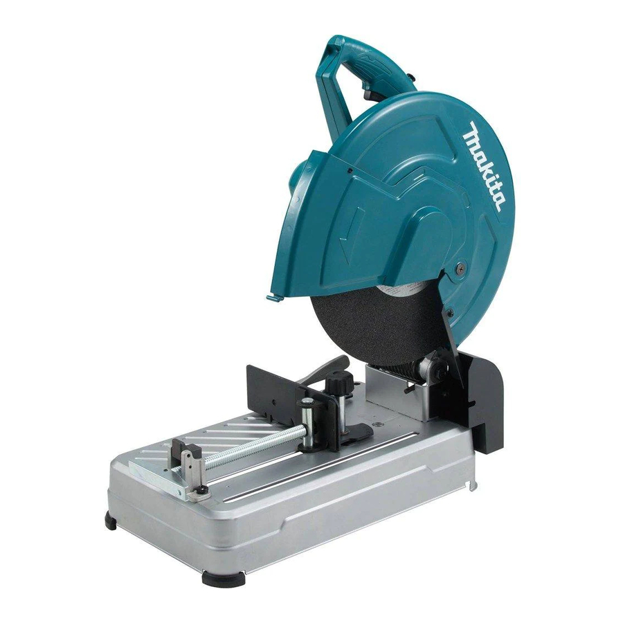
Model LW1401 is a powerful (2200W) 355mm (14")
Portable Cut-off and the successor to the current model
2414NB. Replacement of Abrasive cut-off wheel and
adjustment of Guide plate can be done without any
tools.
Toolless
Model No.
abrasive cut-off
wheel change
LW1400
Yes
LW1401
No
S
pecification
Voltage (V)
Current (A)
110
120
220
230
240
Specification
Diameter
Wheel
size: mm (") Hole diameter
Thickness
No load speed: min
= rpm
-1
Wheel change
Toolless
Guide plate adjustment
Quick release vise
Saw head locking device
for storage and transport
Protection from electric shock
Power supply cord: m (ft)
Weight according to
EPTA-Procedure 01/ver.2.1*1: kg (lbs)
Capacity: mm (")
Cross section of
workpiece
D: Diameter
W: Width
H: Height
S: Side
T: Thickness
*1 With Abrasive cut-off wheel 355 *2 For North America and South America *3 For Europe
*4 For all countries except North America, South America and Europe
LW1400/LW1401
355mm (14") Portable Cut-off
Toolless
Large
guide plate
spark guard
adjustment
Yes
Yes
Depends on
No
country
Cycle (Hz)
15
50/60
15
50/60
10.5
50/60
10
50/60
9.6
50/60
Model
Miter angle
D
W
H x W
H
W
H x W
119 (4-11/16) x 119 (4-11/16)
H
S
S
S x S
T
T
W
Note:
For some countries, product appearances may vary from
the above images because some parts are country-specific.
Length (L)
Width (W)
Height (H)
Continuous Rating (W)
Input
1,650
---
2,200
2,200
2,200
LW1400
Yes
Yes
Pin
Double insulation
Australia, Brazil: 2.0 (6.6), Other countries: 2.5 (8.2)
17.2 (37.9)
, 18.7 (41.2)
*2
*3
17.0 (37.5)
*4
90°
ø127 (5)
115 (4-1/2) x 130 (5-1/8)
102 (4) x 194 (7-5/8)
70 (2-3/4) x 233 (9-1/8)
137 (5-3/8) x 137 (5-3/8)
10 (3/8)
OFFICIAL USE
for ASC & Sales Shop
January 2016
H
L
LW1400
Dimensions: mm (")
LW1401
LW1400
Europe
530 (20-7/8)
500 (19-3/4)
295 (11-5/8)
295 (11-5/8)
640 (25-1/4)
640 (25-1/4)
Max Output (W)
Output
800
800
1,350
1,350
1,350
LW1401
355 (14)
25.4 (1)
3 (1/8)
3,800
No
No
Yes
Chain
,
16.8 (37.0)
, 18.3 (40.3)
*2
16.6 (36.6)
45°
ø127 (5)
115 (4-1/2) x 103 (4-1/16)
106 (4-3/16) x 106 (4-3/16)
100 (4) x 100 (4)
10 (3/8)
PRODUCT
P 1/ 15
LW1401
Except Europe
290 (11-3/8)
620 (24-3/8)
3,200
3,200
3,600
3,600
3,600
,
*3
*4
Advertisement
Table of Contents

Related Manuals for Makita LW1400


Summary of Contents for Makita LW1400
- Page 1 OFFICIAL USE for ASC & Sales Shop ECHNICAL INFORMATION PRODUCT P 1/ 15 Model No. LW1400/LW1401 January 2016 Description 355mm (14") Portable Cut-off ONCEPT AND MAIN APPLICATIONS Model LW1401 is a powerful (2200W) 355mm (14") Portable Cut-off and the successor to the current model 2414NB.
-
Page 2: Table Of Contents
· It is also recommended to have boxes ready to keep disassembled parts by group. · Handle the disassembled parts carefully. · If some bolts and screws are too tight, use an impact driver. · Tighten the bolts and the screws to the specified torque. Makita Corporation 2 / 15... -
Page 3: Repair
Retaining ring S and R pliers 1R291 removing Retaining ring 1R269 Bearing extractor removing Ball bearing 6000ZZ Spring pin extractor 4.0 1R308 extracting Spring pin 4 Spring pin extractor 5.0 1R309 extracting Spring pin 5 Makita Corporation 3 / 15... -
Page 4: Lubricant And Adhesive Application
On the outer periphery of O ring 7 (114) Outer periphery of Sleeve 20 (112) attached Stopper pin (only LW400) Apply Makita grease F A No. 2 to fill the gap between Safety cover (17) and Ring 17 (14) for dust-proof. Ring 17 (14) -
Page 5: Disassembly/Assembly
Compression spring 4 (27) in place. click sound. Note: Fix Switch button Switch (31) after Handle L (30) button (31) is installed. Switch lock (26) Compression Handle L (31) spring 4 (27) Switch lever (25) Makita Corporation 5 / 15... -
Page 6: Helical Gear 50
Helical gear Arbor press Groove: 30mm 50 (20) Fig. 3-6 The component of Gear section is as follows. Bearing box (19) Helical gear 50 (20) Spindle (21) Ball bearing 6000ZZ (22) Ball bearing 6203ZZ (18) Makita Corporation 6 / 15... - Page 7 After removing O ring 65 (1) from Bearing box (19), lubricate Makita grease FA No.2. Note: Be sure to attach O ring 65 (1) to Bearing box (19). And then apply Makita grease FA No.2 to avoid tear of the O ring. O ring 65 (1)
-
Page 8: Vise Section
Screw guide (67) Vise nut (65) Note: Directional Vise screw (60) IR 258 **Spring pin 5-36 (68) *Spring pin 4-16 (69) **Spring pin 5-20 (58) * with 1R308 to assemble ** with 1R309 to assemble Makita Corporation 8 / 15... -
Page 9: Guide Plate
Flat washer 8 (91) 1R291 Vise plate (92) wide narrow 5-3-5 Guide plate 5-3-5-1 Disassembling (LW1400’s case) Fig. 5-1 Fig. 5-2 Fig. 5-3 Loosen Knob 40 (72) and then Remove Lever 125 (101) by Remove Stop ring E-8 (110) with remove Guide plate (73) from loosening M5x6 H.S.Set screw... - Page 10 Lever 125 (101) must be mounted within 20 degrees from then fix it with M5x6 H.S.Set screw (100). perpendicular to the surface of Base (86). M5x6 H.S.Set screw (100) Lever 125 (101) Lever 125 (101) Within 20° Guide plate (73) Base (86) Makita Corporation 10 / 15...
-
Page 11: Main Frame, Base And Others
(74) with Wrench 17 and Socket bit 17 and Cordless Hold Gear housing complete firmly and then release impact driver. Note: Before assembling, apply Makita grease FA No.2 a Stopper pin (115) or Chain (64) slowly to move up Gear housing complete. - Page 12 Spark guard Spark guard Spark guard Base Base Base Fig. 6-10 Note: To prevent melting by heated chips, Cushion (83) is not installed at Spark guard (81) position. Spark guard (81) Base (86) Cushion (83) Makita Corporation 12 / 15...
-
Page 13: Circuit Diagram
Non-insulated connector Black/AWG16 Switch Line filter Blue or white Black/AWG16 Power supply cord Line filter Brown or black White/AWG16 Noise suppressor Choke coil White/AWG20 Black/AWG16 Tool head Field Rear side of tool Non-insulated connector Black/AWG16 Black/AWG16 Makita Corporation 13 / 15... -
Page 14: Wiring Diagram
Put Field into Motor housing as shown below. as shown · below <Except UK 110V> Field lead wire(White) Lead wire holder Field lead wire(Black) < UK 110V> Field lead wire (Black, White) Lead wire holder Makita Corporation 14 / 15... - Page 15 Field Lead wire (White) has to be fixed in this Field Lead wire has to be fixed through the Lead wire holder. hole of Line filter between Rib B and Lead wire holder A. (When Line filter is used.) Makita Corporation 15 / 15...