Table of Contents
Advertisement
Quick Links
USE, INSTALLATION AND MAINTENANCE
INSTRUCTIONS FOR BUILT-IN HOT PLATES
Dear Customer
Thank you for purchasing a Omega Cooktop.
You will find that the clean lines and modern look of your Omega Cooktop blends perfectly with your kitchen décor.
It is easy to use and performs to a high standard.
Omega also makes a range of products that will enhance your kitchen such as ovens, rangehoods, dishwashers,
microwaves, sinks and taps.
There are models to complement your new Omega Cooktop.
Of course we make every effort to ensure that our products meet all your requirements, and our Customer
Relations department is at your disposal, to answer your questions and to listen to all your suggestions (see back
cover of manual).
Please complete the warranty section of this manual and keep your receipt as proof of purchase. Retain all
documents relating to the purchase of this products.
Omega is committed to providing increasingly efficient products that are easy to use, respect the environment and
are attractive and reliable.
OMEGA
We ask that you carefully read the instructions within this booklet to enable you to abtain quality results from the outset.
The appliance must be installed only by an authorised person in compliance with the instructions provided. The manufacturer declines
all responsibility for improper installation which may harm persons and animals and damage property.
The appliance must be used for the purpose for which it was expressly designed. Any other use (eg heating rooms) is considered to be
improper and consequently dangerous. The manufacturer declines all responsibility for damage resulting from improper and
irresponsible use.
The manufacturer shall not be held responsible for any inaccuracies in this handbook due to printing or transcription errors. The
designs in the figures are purely indicative.
The manufacturer also reserves the right to make any modifications to the products as may be considered necessary, useful or in the
interests of the user, without jeopardizing the main functional and safety features on the products themselves.
If your cooktop requires service, please contact the Omega customer service centre.
MODEL: OCG755FX
PLEASE READ THIS MANUAL BEFORE
INSTALLING THE HOTPLATE.
COD. 04077NA - 27.10.2017
Advertisement
Table of Contents

Related Manuals for Omega OCG755FX


Summary of Contents for Omega OCG755FX
- Page 1 Dear Customer Thank you for purchasing a Omega Cooktop. You will find that the clean lines and modern look of your Omega Cooktop blends perfectly with your kitchen décor. It is easy to use and performs to a high standard.
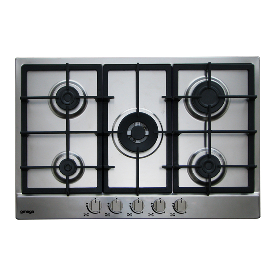
- Page 3 DESCRIPTION OF THE HOTPLATE MOD: OCG755FX Overall measurement (mm) Width 750 x Depth 500 x Height 40 To use the WOK pan support on Wok gas burner only. Put it on the WOK pan support and make sure of the stability (see fig. A).
- Page 4 1) BURNERS Power ratings Pan Ø A diagram is screen-printed above each knob on the Burners in cm front panel. This diagram indicates to which burner Natural U-LPG the knob in question corresponds. After having opened the gas mains or gas bottle tap, light the 15.5 12.6 MJ/h 24 - 26...
- Page 5 WARNINGS AND ADVICE FOR THE USER: - use of a gas cooking appliance produces heat and moisture in the room in which it is installed. The room must therefore be well ventilated by keeping the natural air vents clear (fig. 3) and by activating the mechanical aeration device (suction hood or electric fan fig.
- Page 6 CLEANING IMPORTANT: - Do not force the taps if they are difficult to open or close. Contact the technical always disconnect the appliance from the gas assistance service for repairs. and electricity mains before carrying out any - Don’t use steam jets for cleaning the hotplate. cleaning operation.
-
Page 7: Installation
INSTALLATION TECHNICAL INFORMATION FOR hotplate must be at least 650 mm above the top of the INSTALLATION PERSONNEL burner and no construction shall be within 450 mm above the top of the burner. A minimum depth of 70 mm from the top (fig.7) of the worktop surface must be provided for the IMPORTANT: perfect... - Page 8 INSTALLATION 4) FIXING THE HOTPLATE - Fix the hob with the proper brackets “S” and fit the prominent part into the porthole “H” on the bottom; The hot plate has a special seal which prevents turn the screw “F” until the bracket “S” stick on the liquid from infiltrating into the cabinet.
-
Page 9: Gas Connection
Assemble the regulator (noting the gas flow (100 mm mod: OCG755FX) direction) and transition piece, in accordance with figure 11. There are two ways to carry out the connection to the... -
Page 10: Electrical Connection
INSTALLATION 6) ELECTRICAL CONNECTION Letter L (live) = brown wire; Letter N (neutral) = blue wire; Earth symbol = green - yellow wire. IMPORTANT: the appliance must be installed following the manufacturer's instructions. The - The power supply cable must be positioned so that no manufacturer will not be liable for injury to part of it is able to reach an overtemperature of 90 °C. - Page 11 ADJUSTMENTS Always disconnect the appliance from the (fig 14/A). Turn the throttle screw to the right or left electricity main before making any adjustments. until the burner flame has been adequately All seals must be replaced by the technician at regulated to the “Reduced rate”...
-
Page 12: Conversion Procedure
Appliance models: Gas stainless steel hotplate Appliance models: Gas stainless steel hotplate models: models: OCG755FX 5 Burners OCG755FX 5 Burners 1. Remove each burner cap and burner skirt. 1. Remove each burner cap and burner skirt. 2. Remove the Natural Gas main injector with a 2. -
Page 13: Replacing The Injectors
CONVERSIONS 10) REPLACING THE INJECTORS paragraphs 7. The technician must reset any seals on the regulating or pre-regulating The burners can be adapted to different types of devices. gas by mounting injectors suited to the type of gas The envelope with the injectors and the labels in question. - Page 14 SERVICING CABLE TYPES AND SECTIONS TYPE OF TYPE OF SINGLE - PHASE HOT PLATE CABLE POWER SUPPLY Gas hot plate H05 RR - F Section 3 X 0.75 mm ATTENTION!!! If the power supply cable is replaced, the installer should leave the ground wire (B) longer than the phase conductors (fig.
-
Page 15: Technical Assistance And Spare Parts
TECHNICAL ASSISTANCE AND SPARE PARTS Before leaving the factory, this appliance will have been tested and regulated by expert and specialised personnel in order to guarantee the best performances. Any repairs or adjustments which may be subsequently required may only be carried out by qualified personnel with the utmost care and attention.