Table of Contents
Advertisement
Model 141/161
Operator's Manual
WARNING!
Read this Operator's Manual
carefully before using this
tool. Failure to understand
and follow the contents of
this manual may result in
electrical shock, fire and/or
serious personal injury.
Receding Geared Threaders
99 Washington Street
Melrose, MA 02176
Phone 781-665-1400
Toll Free 1-800-517-8431
Visit us at www.TestEquipmentDepot.com
Advertisement
Table of Contents

Related Manuals for RIDGID 141


Summary of Contents for RIDGID 141
- Page 1 Receding Geared Threaders Model 141/161 Operator’s Manual WARNING! Read this Operator’s Manual carefully before using this tool. Failure to understand and follow the contents of this manual may result in electrical shock, fire and/or 99 Washington Street serious personal injury.
-
Page 2: Safety Symbols
Model 141/161 Receding Geared Threaders Safety Symbols In this operator’s manual and on the product, safety symbols and signal words are used to communicate important safe- ty information. This section is provided to improve understanding of these signal words and symbols. -
Page 3: Specific Safety Information
• Use personal protective equipment. Always wear eye protection. Protective equipment such as dust Read these precautions carefully before using Model 141/161 Receding Geared Threaders to mask, non-skid safety shoes, hard hat, or hearing reduce the risk of electrical shock or other serious protection used for appropriate conditions will reduce injury. -
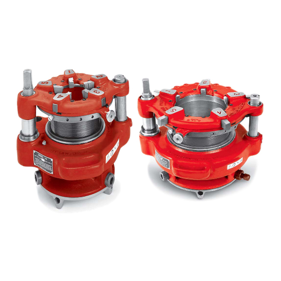
Page 4: Description, Specifications And Standard Equipment
Model 141/161 Receding Geared Threaders • Follow instructions on proper use of this machine. The 141 and 161 can be powered in a variety of ways, Do not use for other purposes such as drilling including operation by hand or with various RIDGID Threading Machines and Power Drives. -
Page 5: Pre-Operation Inspection
The Receding Geared Threaders can be adjusted for correct any problems to reduce the risk of serious injury from electrical shock, crushing injuries and different thread size and types. Model 141 Threader can other causes and prevent machine damage. thread 2 ", 3", 3... - Page 6 Model 141/161 Receding Geared Threaders Thread Size Adjustment Guide Post With the drive shaft/die head of geared threader up, turn Angled Slot the drive shaft or gear case by hand. Align the die head Straight Slot with appropriate starting point marks on the guide post or pinion sleeve (see Figure 4) .
-
Page 7: Setup And Operation
3. Inspect the pipe to be threaded and associated fittings Keep hands away from rotating pipe and parts. Do and confirm that the 141 or 161 Geared Threader is a not reach across the machine or pipe. To prevent correct tool for the job. See the Specifications. - Page 8 Lifting by hand must be done by at least two people utilizing the carrying handles. Be aware that the 141 weighs 93 pounds and the 161 weighs 158 pounds. Carefully center end of pipe in throat of the dies and turn workholder scroll to tighten jaws on pipe.
- Page 9 Model 141/161 Receding Geared Threaders 6. Remove the ratchet and turn over. Rotate the drive- Do not insert from the front (carriage) end of the machine. shaft counterclockwise to back the die head up approximately one turn. 5. Align and slip the square socket of the 840A driveshaft 7.
- Page 10 3. Inspect the pipe to be threaded and associated fittings Figure 11 – Threading With Universal Driveshaft and confirm that the 141 or 161 Geared Threader is 11. Press the foot switch to start threading. Flood the dies a correct tool for the job. See the Specifications.
- Page 11 Lifting by hand must be done by at least two people utilizing the carrying handles, be aware that the 141 weighs 93 pounds (42 kg) and the 161 weighs 158 pounds (72 kg). Leave approximately " of the drive bar exposed in front of the chuck to allow space for oiling (Figure 12).
- Page 12 Figure 15 – 844 Drive Bar and 768 Drive Link Installed Leveling Saddle Figure 18 – Flexible Oil Spout Routing Setting up 535A Close Coupled to 141 Geared Threader 1. Place the leveling saddle on the carriage as shown in Figure 16 – Saddle on 535 Carriage Figure 16.
- Page 13 5. If using a 300 Power Drive, place 418 Oiler bucket Mounting Hole under the geared threader. If using 300A Power Drive Figure 19 – 141 Threader Close Coupled To 535A Threading Machine or a threading machine, route the flexible oil spout so nozzle applies oil between chaser #1 and 2 (Figure 18) .
- Page 14 Model 141/161 Receding Geared Threaders barrel, DO NOT try to re-engage the thread under 9. Press the foot switch to start threading. Flood the power. Remove the geared threader from the machine dies with oil to lower threading torque, improve thread and re-engage by hand.
- Page 15 To reduce the risk of serious injury, only use acces- safe to operate. sories specifically designed and recommended for use with the 141 and 161 Receding Geared Thread - The “Maintenance Instructions” will take care of most of ers such as those listed below. Other Accessories the service needs of this machine.
-
Page 16: Troubleshooting
Model 141/161 Receding Geared Threaders Troubleshooting PROBLEM POSSIBLE REASONS SOLUTION Torn threads. Damaged, chipped or worn out dies. Replace dies. Incorrect cutting oil. Only use RIDGID ® Thread Cutting Oil. Insufficient cutting oil. Flood the dies with oil during use. - Page 17 Visit us at www.TestEquipmentDepot.com E M E R S O N . C O N S I D E R I T S O L V E D . ™ Printed in U.S.A 2/13 999-999-466.10 © 2013 RIDGID, Inc. EC39645 REV. A...