Table of Contents
Advertisement
Advertisement
Table of Contents

Related Manuals for Cisco Catalyst 9800-80


Summary of Contents for Cisco Catalyst 9800-80
- Page 1 Cisco Catalyst 9800-80 Wireless Controller Hardware Installation Guide First Published: 2018-11-20 Americas Headquarters Cisco Systems, Inc. 170 West Tasman Drive San Jose, CA 95134-1706 http://www.cisco.com Tel: 408 526-4000 800 553-NETS (6387) Fax: 408 527-0883...
- Page 2 Cisco has more than 200 offices worldwide. Addresses and phone numbers are listed on the Cisco website at www.cisco.com/go/offices. Cisco and the Cisco logo are trademarks or registered trademarks of Cisco and/or its affiliates in the U.S. and other countries. To view a list of Cisco trademarks, go to this URL: www.cisco.com...
-
Page 3: Table Of Contents
Serial Number and PID or VID Label Location C H A P T E R 2 Supported Hardware Components Supported EPA Supported SFP Models Supported Transceivers Supported Crypto Module Power Supplies Power Supply LEDs Cisco Catalyst 9800-80 Wireless Controller Hardware Installation Guide... - Page 4 General Rack-Selection Guidelines Guidelines for 23-in. (Telco) Racks Equipment Rack Guidelines Preventing Electrostatic Discharge Damage Electrical Safety Chassis-Lifting Guidelines Tools and Equipment Unpacking and Verifying Shipping Contents Checking the Shipping Container Contents Installation Checklist Cisco Catalyst 9800-80 Wireless Controller Hardware Installation Guide...
- Page 5 Configuring the Controller Hostname Configuring the Enable and Enable Secret Passwords Configuring the Console Idle Privileged EXEC Timeout Gigabit Ethernet Management Interface Overview Default Gigabit Ethernet Configuration Configuring Gigabit Ethernet Interfaces Saving Your Controller Configuration Cisco Catalyst 9800-80 Wireless Controller Hardware Installation Guide...
- Page 6 A P P E N D I X A Technical Specifications Technical Specifications A P P E N D I X B Port Signals and Pinouts Management Ethernet Port Signals and Pinouts Console Port Signals and Pinouts Cisco Catalyst 9800-80 Wireless Controller Hardware Installation Guide...
- Page 7 November 2018 First version of the document. Document Objectives This publication describes the installation of the Cisco Catalyst 9800-80 Wireless Controller. Audience This publication is primarily designed for persons responsible for installing, maintaining, and troubleshooting the Cisco Catalyst 9800-80 Wireless Controller. The users of this guide should: •...
- Page 8 Means the following information will help you solve a problem. The tips information might not be troubleshooting or even an action, but could be useful information, similar to a Timesaver. Cisco Catalyst 9800-80 Wireless Controller Hardware Installation Guide viii...
- Page 9 What's New in Cisco Product Documentation. To receive new and revised Cisco technical content directly to your desktop, you can subscribe to the What's New in Cisco Product Documentation RSS feed. RSS feeds are a free service.
- Page 10 Preface Obtaining Documentation and Submitting a Service Request Cisco Catalyst 9800-80 Wireless Controller Hardware Installation Guide...
-
Page 11: Overview
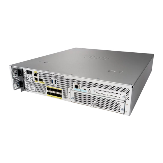
C H A P T E R Overview The Cisco Catalyst 9800-80 Wireless Controller is an 80-G wireless controller that occupies two rack unit space and supports a single Ethernet Port Adapter (EPA) slot, and eight built-in 10-GE or 1-GE interfaces. -
Page 12: Chapter
• Field-replaceable units (FRU). See Chapter 2, Supported Hardware Components for information on supported FRUs. Front View The following figure shows the front of the Cisco Catalyst 9800-80 Wireless Controller. Figure 1: Cisco Catalyst 9800-80 Wireless Controller Front View Power supply (PEM 0) RP—... -
Page 13: Built-In Sfp And Sfp+ Ports
Note By default, the interfaces from 0 to 3 on both Bay 0 and Bay 1 on the Cisco Catalyst 9800-80 Wireless Controller are enabled. You can enable the interfaces from 4 to 7 by purchasing the Paired Port License. -
Page 14: Management And Storage Connections
RDCY— 1-GE SFP+ port. CON— RJ-45 compatible console port. USB port 0 SSD Access LEDs The following figure shows the LEDs on the front panel of the Cisco Catalyst 9800-80 Wireless Controller. Cisco Catalyst 9800-80 Wireless Controller Hardware Installation Guide... - Page 15 Overview LEDs Figure 4: Cisco Catalyst 9800-80 Wireless Controller LEDs LED Label Description LED Color Behavior Power Green If all the power rails are based on the specification. System Remains ON during IOS boot complete. Blinking Green Remains blinking when IOS booting is in progress.
- Page 16 Cold. Blinks Fast Blinks fast during HA maintenance. USB console Green Indicates that the enabled mini USB connector is used as the console. SSD Activity Green Remains ON during the SSD activity. Cisco Catalyst 9800-80 Wireless Controller Hardware Installation Guide...
-
Page 17: Rear View
The fans are numbered from 0 to 3, right to left. Caution The power supplies used in Cisco Catalyst 9800-80 Wireless Controllers are different and they should not be mixed or swapped. The size and structural dimensions are the same, therefore they both look alike. It would be hazardous, if you accidentally inserted the wrong power supply into the PEM slot. - Page 18 Additional product information Description The combination of serial number and product ID (PID) is unique and consistent across all Cisco products. The PID that is coded on hardware is called a base product identifier. Additional orderable PIDs can be associated to a base PID. For instance, an orderable PID may describe a packaging configuration for a product or a bundled group of products sold, tested, and shipped together.
-
Page 19: Serial Number And Pid Or Vid Label Location
Common Language Equipment Identification (CLEI) code is a ten-digit character code that identifies a specific product. A CLEI code is applied to each part within a Cisco Catalyst 9800-80 Wireless Controller as they are programmed in manufacturing for shipment to customers. - Page 20 Overview Serial Number and PID or VID Label Location Figure 6: Cisco Catalyst 9800-80 Wireless Controller Serial Number and PID/VID Label Location Serial Number PID/VID Label Cisco Catalyst 9800-80 Wireless Controller Hardware Installation Guide...
-
Page 21: Supported Hardware Components
C H A P T E R Supported Hardware Components This chapter contains information about the supported hardware components on the Cisco Catalyst 9800-80 Wireless Controller. • Supported EPA, on page 11 • Supported SFP Models, on page 13 •... - Page 22 Supported Hardware Components Supported EPA Figure 7: EPA-18X1GE LEDs Figure 8: EPA-10X10GE LEDs STATUS Cisco Catalyst 9800-80 Wireless Controller Hardware Installation Guide...
-
Page 23: Supported Sfp Models
EPA power is on and good, and the EPA is being configured. EPA power is off. Supported SFP Models The following table lists the supported SFP models [40-GB and 100-GB] on the Cisco Catalyst 9800-80 Wireless Controller. Table 3: SFP Model [40-GB]... -
Page 24: Supported Transceivers
Supported Hardware Components Supported Transceivers Supported Transceivers The Cisco Catalyst 9800-80 Wireless Controller supports the following small form-factor pluggable (SFP) and CPAK optical transceiver types: Ports Cisco Catalyst 9800-80 Wireless Controller Ports TE0 – TE7 use 1GE or 10GE SFP+ SFP+ EPA-18X1GE—... -
Page 25: Supported Crypto Module
Crypto performance. Power Supplies The Cisco Catalyst 9800-80 Wireless Controllers support AC or DC power supply options. The modular chassis configurations support the installation of two power supplies for redundancy. When an external power supply fails or is removed, the other power supply provides power requirements for the chassis. This allows you to hot-swap the power supply without impacting the functionality of the controller. -
Page 26: Power Supply Fans
Fan failure is determined by fan-rotation sensors. Note The fans in the Cisco Catalyst 9800-80 Wireless Controller power supplies have plug-side intake airflow. Caution The chassis has a front-to-rear airflow. All of the power supplies and fan modules in the same chassis must use the same airflow direction or an error will occur with possible overheating and shut down of the controller. -
Page 27: Preparing Your Site For Installation
• Ensure that you have all of the necessary tools and equipment (see the Tools and Equipment section). • Ensure that you have access to the Cisco Catalyst 9800-80 Wireless Controller Software Configuration Guide (an online document that is available for viewing or download at Cisco.com) during the installation. -
Page 28: Site Planning Checklist
• Controller should always be transported or stored in its shipping package in the upright position. • Keep the controller in the shipping container until you have determined the installation site. Note Inspect all items for shipping damage. If an item appears damaged, contact a Cisco customer service representative immediately. Site Planning Checklist Use the following checklist to perform and account for all the site-planning tasks described in this chapter: •... -
Page 29: Safety Recommendations
Safety Recommendations The following guidelines will help to ensure your own safety and protect your Cisco equipment. This list does not cover all potentially hazardous situations, so be alert. • Cisco safety policy mandates that all its controllers must conform to the requirements of IEC 60950, with appropriate national deviations, as a minimum. -
Page 30: Standard Warning Statements
Use the statement number provided at the end of each warning to locate its translation in the translated safety warnings that accompanied this device. SAVE THESE INSTRUCTIONS Cisco Catalyst 9800-80 Wireless Controller Hardware Installation Guide... -
Page 31: General Safety Warnings
• 20 A U.S. maximum Warning Statement 1045—Short-circuit Protection This product requires short-circuit (overcurrent) protection to be provided as part of the building installation. Install only in accordance with national and local wiring regulations. Cisco Catalyst 9800-80 Wireless Controller Hardware Installation Guide... - Page 32 Warning Statement 1034—Backplane Voltage Hazardous voltage or energy is present on the backplane when the system is operating. Use caution when servicing. Warning Statement 1008—Class 1 Laser Product Class 1 laser product. Cisco Catalyst 9800-80 Wireless Controller Hardware Installation Guide...
- Page 33 To prevent personal injury or damage to the chassis, never attempt to lift or tilt the chassis using the handles on modules (such as power supplies, fans, or cards); these types of handles are not designed to support the weight of the unit. Cisco Catalyst 9800-80 Wireless Controller Hardware Installation Guide...
-
Page 34: Site Planning
Site Selection Guidelines The Cisco Catalyst 9800-80 Wireless Controller requires specific environmental operating conditions. Temperature, humidity, altitude, and vibration can affect the performance and reliability of the controller. The following sections provide specific information to help you plan for a proper operating environment. -
Page 35: Site Environmental Requirements
122° F (50° C) C per minute Physical Characteristics Be familiar with the physical characteristics of the Cisco Catalyst 9800-80 Wireless Controller to assist you in placing the system at a proper location. Note For information regarding rack widths supported for the controller, see the following sections: •... -
Page 36: Site Power Guidelines
Preparing Your Site for Installation Site Power Guidelines The following table shows the weight and dimensions of the Cisco Catalyst 9800-80 Wireless Controller: Table 9: Physical Characteristics of the Cisco Catalyst 9800-80 Wireless Controller Characteristic Cisco Catalyst 9800-80 Wireless Controller Height 3.5 in. -
Page 37: Electrical Circuit Requirements
The Cisco Catalyst 9800-80 Wireless Controller can only be powered by an AC source. Ensure that equipment grounding is present and observe power-strip ratings. Make sure that the total ampere rating of all the products plugged into the power strip does not exceed 80 percent of the rating. -
Page 38: Console Port Connections
Console Port Connections The Cisco Catalyst 9800-80 Wireless Controller provides console ports to connect a terminal or computer for local console access. Both ports have RJ-45 connectors, support RS-232 asynchronous data, and have distance recommendations specified in the IEEE RS-232 standard. - Page 39 Preparing Your Site for Installation Interference Considerations The following sections describe sources of interference and how to minimize its effects on Cisco Catalyst 9800-80 Wireless Controller. Electromagnetic Interference All the equipment powered by AC current can propagate electrical energy that can cause electromagnetic interference (EMI) and possibly affect the operation of other equipment.
-
Page 40: Rack-Mounting Guidelines
General Rack-Selection Guidelines The Cisco Catalyst 9800-80 Wireless Controller can be mounted in most two-post or four-post, 19-in. equipment racks that comply with the Electronics Industries Association (EIA) standard for equipment racks (EIA-310-D 19-in.). The rack must have at least two posts with mounting flanges to mount the chassis. -
Page 41: Guidelines For 23-In. (Telco) Racks
Locating for Safety If the Cisco Catalyst 9800-80 Wireless Controller is the heaviest or the only piece of equipment in the rack, consider installing it at or near the bottom to ensure that the rack’s center of gravity is as low as possible. -
Page 42: Preventing Electrostatic Discharge Damage
Environmental Monitoring and Reporting Functions section. • Keep the Cisco Catalyst 9800-80 Wireless Controller off the floor and out of the areas that collect dust. • Follow ESD-prevention procedures to avoid damage to equipment. Damage from static discharge can cause immediate or intermittent equipment failure. -
Page 43: Electrical Safety
• Use caution when installing or modifying telephone lines. Warning Statement 1001—Work During Lightning Activity Do not work on the system or connect or disconnect cables during periods of lightning activity. Cisco Catalyst 9800-80 Wireless Controller Hardware Installation Guide... -
Page 44: Chassis-Lifting Guidelines
The following tools and equipment are recommended as the minimum necessary equipment to install the Cisco Catalyst 9800-80 Wireless Controller. You may need additional tools and equipment to install associated equipment and cables. You may also require test equipment to check electronic and optical signal levels, power levels, and communications links. -
Page 45: Checking The Shipping Container Contents
Checking the Shipping Container Contents Use the components list shown in the following table to check the contents of the Cisco Catalyst 9800-80 Wireless Controller shipping container. Do not discard the shipping container. You need the container, if you move or have to ship the controller in the future. - Page 46 AC power cable(s) connected to AC source(s) and controller DC power cable(s) connected to source(s) and controller Network interface cables and devices connected System power turned on System boot complete (STATUS LED is on) Cisco Catalyst 9800-80 Wireless Controller Hardware Installation Guide...
- Page 47 Preparing Your Site for Installation Installation Checklist Task Verified By Date Ethernet port adapters and NIMs (where applicable) are operational Correct hardware configuration displayed after system banner appears Correct licenses installed on the controller Cisco Catalyst 9800-80 Wireless Controller Hardware Installation Guide...
- Page 48 Preparing Your Site for Installation Installation Checklist Cisco Catalyst 9800-80 Wireless Controller Hardware Installation Guide...
-
Page 49: Installing The Controller
C H A P T E R Installing the Controller This chapter provides procedures for installing the Cisco Catalyst 9800-80 Wireless Controller on an equipment shelf, tabletop, or in an equipment rack. • Installation Methods, on page 39 • Guidelines for a Standalone Equipment Shelf or Tabletop Installation, on page 40 •... -
Page 50: Guidelines For A Standalone Equipment Shelf Or Tabletop Installation
• The Cisco Catalyst 9800-80 Wireless Controller requires at least 3 inches (7.62 cm) of clearance at the inlet and exhaust vents (the front and rear sides of the chassis). -
Page 51: Guidelines For Rack Installation
Installing the Controller Guidelines for Rack Installation Step 3 to Step 9 are optional, if you are installing the Cisco Catalyst 9800-80 Wireless Controller on a rack Note shelf. The chassis rack-mount brackets must be installed prior to installing the cable-management brackets. -
Page 52: Verifying Rack Dimensions
Caution To prevent chassis overheating, never install a Cisco Catalyst 9800-80 Wireless Controller in an enclosed space that is not properly ventilated or air conditioned. • Always install heavier equipment in the lower half of a rack to maintain a low center of gravity to prevent the rack from falling over. -
Page 53: Attaching Front Rack-Mount Brackets
Locate the threaded holes on the side of the chassis. Ensure that you hold the front rack-mount bracket with the ear and holes facing outward and towards the front of the chassis. The following figure shows where to attach the front rack-mount brackets to the Cisco Catalyst 9800-80 Wireless Controller. Cisco Catalyst 9800-80 Wireless Controller Hardware Installation Guide... -
Page 54: Mounting The Controller In The Rack
Because the rack-mount brackets support the weight of the entire chassis, ensure that you use all the screws to fasten the two rack-mount brackets to the rack posts. Cisco Catalyst 9800-80 Wireless Controller Hardware Installation Guide... -
Page 55: Two-Post Rack Installation
Step 3 (Optional) Install a shelf in the rack to support the Cisco Catalyst 9800-80 Wireless Controller. If you use a shelf, it helps support the chassis while you secure it to the rack. If you are using a shelf, place the chassis on the shelf and slightly raise the front of the chassis to align the Note mounting bracket holes with the rack post holes while allowing the bottom of the chassis to rest on the shelf. -
Page 56: Attaching The Cable Management Bracket
Tighten all the screws on each side to secure the chassis to the equipment rack. The following figure shows the Cisco Catalyst 9800-80 Wireless Controller on a two-post equipment rack. Figure 10: Cisco Catalyst 9800-80 Wireless Controller Installed on a Two-Post Equipment Rack... - Page 57 Make certain that the cable-management bracket "U" feature is facing upwards when you attach it to the chassis. Step 1 Align the cable-management bracket to the rack-mount bracket on one side of the Cisco Catalyst 9800-80 Wireless Controller. The cable-management bracket aligns to the top hole of the chassis rack-mount bracket.
-
Page 58: Chassis Ground Connection
Repeat step 1 to step 3 for the other side of the chassis. Chassis Ground Connection Connecting the Cisco Catalyst 9800-80 Wireless Controller chassis to ground is required for any AC powered installation where compliance with Telcordia grounding requirements is necessary. - Page 59 Locate the chassis ground connector on the side of your chassis. Step 5 Insert the two screws through the holes in the grounding lug. The following figure shows how to attach a grounding lug to the chassis ground connector. Cisco Catalyst 9800-80 Wireless Controller Hardware Installation Guide...
-
Page 60: Connecting Cables
Installing the Controller Connecting Cables Figure 13: Attaching the Grounding Lug to the Ground Connector of the Cisco Catalyst 9800-80 Wireless Controller Ground connector on the chassis Grounding screws Chassis ground lug Ground symbol Step 6 Use the Number 2 Philips screwdriver to carefully tighten the screws until the grounding lug is held firmly to the chassis. -
Page 61: Connecting The Console Port Cable
9600 baud, 8 data bits, no parity, 1 stop bits (9600 8N1). Step 2 Connect one end of the RJ-45 cable to the serial RJ-45 console port (CON) on the Cisco Catalyst 9800-80 Wireless Controller using the RJ-45 to DB-9 cable. Connect the DB-9 end to your terminal equipment. -
Page 62: Management Ethernet Port Cable Connection
The default parameters for the console port are 9600 baud, 8 data bits, no parity, and 1 stop bit. For operation with a Microsoft Windows OS version older than Windows 7, the Cisco Windows USB Console Driver must be installed on any PC connected to the console port. If the driver is not installed, the prompts guide you through a simple installation process. -
Page 63: Power Up And Initial Configuration
Note To view the boot sequence, you must have a console connection to the Cisco Catalyst 9800-80 Wireless Controller before it powers up. Ensure that the following conditions are addressed before starting up the controller: •... -
Page 64: Powering Up The Controller
When the system boot is complete (the process takes a few seconds), the controller begins to initialize. Loading from ROMMON with a System Image in Bootflash The following is an example of what is displayed during the system boot process: Initializing Hardware ... Cisco Catalyst 9800-80 Wireless Controller Hardware Installation Guide... - Page 65 (c) (1) (ii) of the Rights in Technical Data and Computer Software clause at DFARS sec. 252.227-7013. Cisco Systems, Inc. 170 West Tasman Drive San Jose, California 95134-1706 Cisco IOS Software [Fuji], WLC9000 Software (X86_64_LINUX_IOSD-UNIVERSALK9_WLC-M), Experimental Cisco Catalyst 9800-80 Wireless Controller Hardware Installation Guide...
- Page 66 ACCEPTANCE OF THE FOLLOWING TERMS. YOU MUST NOT PROCEED FURTHER IF YOU ARE NOT WILLING TO BE BOUND BY ALL THE TERMS SET FORTH HEREIN. Your use of the Software is subject to the Cisco End User License Agreement (EULA) and any relevant supplemental terms (SEULA) found at http://www.cisco.com/c/en/us/about/legal/cloud-and-software/software-terms.html.
-
Page 67: Performing The Initial Configuration On The Controller
The setup command facility is entered automatically if there is no configuration on the controller when it is booted into Cisco IOS-XE. For information on modifying the configuration after you create it, see the Cisco Catalyst 9800 Series Wireless Controller Software Configuration Guide and the Cisco Catalyst 9800 Series Wireless Controller Command Reference Guide. - Page 68 The following configuration command script is created: hostname myWLC enable secret 9 $9$.3E/eKj7KQhfik$6HKawMLMqDjcbKpVUzJ0/I3PwyBnHbIq17OitMW4T.s enable password cisco123 line vty 0 15 password cisco username admin privilege 15 password cisco snmp-server community public interface TenGigabitEthernet0/0/0 Cisco Catalyst 9800-80 Wireless Controller Hardware Installation Guide...
-
Page 69: Completing The Configuration
Completing the Configuration When using the Cisco setup command facility, and after you have provided all the information requested by the facility as described in Using the Cisco setup Command Facility section, the final configuration appears. To complete your controller configuration, follow these steps. -
Page 70: Using The Cisco Ios-Xe Cli-Manual Configuration
You get to view a warning message and require confirmation to proceed with the reload without mentioning a file to boot with. You get to view this message apart from the regular confirmation on the usual reload. Cisco Catalyst 9800-80 Wireless Controller Hardware Installation Guide... -
Page 71: Configuring The Controller Hostname
We recommend that you use the enable secret command because it uses an improved encryption algorithm. Note If you configure the enable secret command, it takes precedence over the enable password command; the two commands cannot be in effect simultaneously. Cisco Catalyst 9800-80 Wireless Controller Hardware Installation Guide... -
Page 72: Configuring The Console Idle Privileged Exec Timeout
Configuring the Console Idle Privileged EXEC Timeout For more information, see the Configuring Passwords and Privileges chapter in the Cisco IOS Security Configuration Guide. Also see the Cisco IOS Password Encryption Facts tech note and the Cisco Guide to Harden Cisco IOS Devices tech note. -
Page 73: Gigabit Ethernet Management Interface Overview
Telnet and SSH to perform management tasks on the controller. The interface is most useful in troubleshooting scenarios when other forwarding interfaces are inactive. Cisco Catalyst 9800-80 Wireless Controller Hardware Installation Guide... -
Page 74: Default Gigabit Ethernet Configuration
• The interface provides a way to access the controller even if forwarding interfaces are not functional, or the Cisco IOS is down. • The management Ethernet interface is part of its own VRF. See the Cisco Catalyst 9800 Series Wireless Controller Software Configuration Guide for more details. -
Page 75: Saving Your Controller Configuration
Note To aid file recovery and minimize downtime in case of file corruption, we recommend that you save backup copies of the startup configuration file and the Cisco IOS-XE software system image file on a server Note To avoid losing work you have completed, be sure to save your configuration occasionally as you proceed. -
Page 76: Verifying The Initial Configuration
Device# copy running-config startup-config Verifying the Initial Configuration Enter the following commands in Cisco IOS-XE to verify the initial configuration on the controller: • show version—Displays the system hardware version, the installed software version, the names and sources of configuration files, the boot images, and the amount of installed DRAM, NVRAM, and flash memory. -
Page 77: Environmental Monitoring And Reporting Functions
Alarm Monitoring The Cisco Catalyst 9800-80 Wireless Controller displays the CRIT, MAJ, and MIN alarm indicator LEDs. These LEDs indicate controller status at all times, but you must directly observe these LEDs to become aware of a controller alarm condition. -
Page 78: Environmental Monitoring
• Input and output voltage • Output current • Outlet temperature The Cisco Catalyst 9800-80 Wireless Controllers are expected to meet the following environmental operating conditions: • Operating Temperature Nominal: 32° to 104° F (0° to 40°C) • Operating Temperature Short Term: 32° to 131° F (0° to 50°C) •... -
Page 79: Fan Failures
The chassis manager on the forwarding engine control processor manages the local resources of the forwarding processor. The Cisco Catalyst 9800-80 Wireless Controller displays warning messages on the console, if the chassis interface-monitored parameters exceed a threshold. You can also retrieve and display environmental status reports with the following commands: •... - Page 80 If you are unable to comply with U.S. and local laws, return this product immediately. A summary of U.S. laws governing Cisco cryptographic products may be found at: http://www.cisco.com/wwl/export/crypto/tool/stqrg.html If you require further assistance please contact us by sending email to export@cisco.com.
- Page 81 NAME: "Chassis 2", DESCR: "Cisco C9800-80-K9 Chassis" PID: C9800-80-K9 , VID: V01 , SN: FXS2209Q2EN NAME: "Chassis 2 Power Supply Module 0", DESCR: "Cisco 750 Watt AC power supply" PID: C9800-AC-750W , VID: V01 , SN: POG22107X2X NAME: "Chassis 2 Fan Tray", DESCR: "Cisco C9800-80-K9 Fan Tray"...
- Page 82 CPU11: CPU Utilization (percentage of time spent) User: 0.09, System: 0.29, Nice: 0.00, Idle: 99.60 IRQ: 0.00, SIRQ: 0.00, IOwait: 0.00 CPU12: CPU Utilization (percentage of time spent) User: 0.00, System: 0.00, Nice: 0.00, Idle: 100.00 Cisco Catalyst 9800-80 Wireless Controller Hardware Installation Guide...
- Page 83 PCB Part Number: XX-XXXX-XX Board Revision: 02 Deviation Number: 0-0 Fab Version: 03 PCB Serial Number: XXXXXXXXXXX RMA Test History: 00 RMA Number: 0-0-0-0 RMA History: 00 Top Assy. Part Number: XX-XXXX-XX CLEI Code: XXXXXXXXXX Cisco Catalyst 9800-80 Wireless Controller Hardware Installation Guide...
- Page 84 Environment Monitor Data: 05 02 03 50 03 58 00 4B Platform features: 00 00 03 56 1E 53 0F 2A 00 00 00 00 00 00 00 00 Power/Fan Module P1 EEPROM data is not initialized Cisco Catalyst 9800-80 Wireless Controller Hardware Installation Guide...
-
Page 85: License Verification
C H A P T E R License Verification This chapter provides information about verifying the Cisco IOS license level and viewing the Cisco Catalyst 9800-80 Wireless Controller license. • Viewing the Cisco IOS License Level, on page 75 •... -
Page 86: Viewing License Information
Field Name Description license boot level adventerprise Indicates the current requested Cisco lOS license level to boot. Viewing License Information Use the show license udi command to determine the Universal Device Identifier (UDI) information of your chassis. This may be required at the time of purchasing a new license. -
Page 87: Removing And Replacing Frus
C H A P T E R Removing and Replacing FRUs This chapter describes procedures for removing and replacing field-replaceable units (FRUs) from Cisco Catalyst 9800-80 Wireless Controller. • Removing AC Power Supplies, on page 77 • Installing AC Power Supplies, on page 77 •... -
Page 88: Removing Dc Input Power Supplies
Before performing any of the following procedures, ensure that power is removed from the DC circuit. Warning Statement 1030—Equipment Installation Only trained and qualified personnel should be allowed to install, replace, or service this equipment. Cisco Catalyst 9800-80 Wireless Controller Hardware Installation Guide... - Page 89 To avoid hazardous conditions, all components in the area where DC input power is accessible must be properly insulated. Therefore, before installing the DC cable lugs, be sure to insulate the lugs according to the manufacturer's instructions. Cisco Catalyst 9800-80 Wireless Controller Hardware Installation Guide...
-
Page 90: Wiring The Dc Input Power Source
Prevent any contact with metal lead on the ground wire and the plastic cover. Wrap the positive and negative lead cables with sleeving. Insulate the lug with shrink sleeving for each lead wire if using noninsulated crimp terminals. Sleeving is not required for insulated terminals. Cisco Catalyst 9800-80 Wireless Controller Hardware Installation Guide... - Page 91 Removing and Replacing FRUs Wiring the DC Input Power Source Figure 15: DC Power Supply Terminal Block Ground Cable Lugs This illustration shows the DC power supply for the Cisco Catalyst 9800-80 Wireless Controller. Note Step 5 For easier cable-management, insert the negative lead cable first.
-
Page 92: Removing And Replacing Usb Flash Memory Stick
Turn the power switch to the On position. The power supply LEDs illuminate green. Removing and Replacing USB Flash Memory Stick The Cisco Catalyst 9800-80 Wireless Controller contains the USB ports for a flash memory stick to store configurations or Cisco IOS XE consolidated packages. Caution Do not remove a USB flash memory stick when issuing a file access command or a read/write operation to the flash memory stick when it is processing. -
Page 93: Appendix A Technical Specifications
A P P E N D I X Technical Specifications This appendix provides technical specifications for the Cisco Catalyst 9800-80 Wireless Controller. • Technical Specifications, on page 83 Technical Specifications Description Specification Dimensions (H x W x D) Height— 3.5 in. (88.9 mm) Width—... - Page 94 Technical Specifications Technical Specifications Cisco Catalyst 9800-80 Wireless Controller Hardware Installation Guide...
-
Page 95: Port Signals And Pinouts
TX/RX DData + T/R Data + (Unused for 10/100) TX/RX DData - T/R Data - (Unused for 10/100) Console Port Signals and Pinouts The following table lists the pinouts of the RJ-45 console port. Cisco Catalyst 9800-80 Wireless Controller Hardware Installation Guide... - Page 96 Request to Send (tied directly to CTS) Output Data Terminal Ready (always On) Output Transmit Data — — — — Input Receive Data Input Unused Input Clear to Send (tied to RTS) Cisco Catalyst 9800-80 Wireless Controller Hardware Installation Guide...