Table of Contents
Advertisement
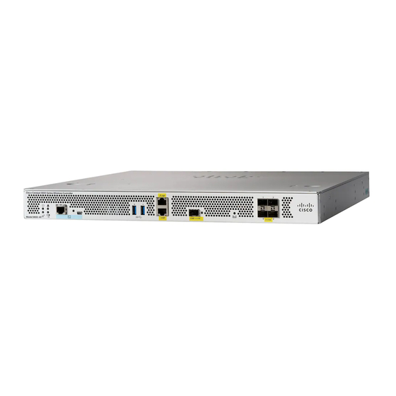
Installing the Controller
This chapter provides procedures for installing the Cisco Catalyst 9800-40 Wireless Controller on an equipment
shelf, tabletop, or in an equipment rack.
•
•
•
•
•
•
•
•
•
•
•
Installation Methods
The Cisco Catalyst 9800-40 Wireless Controller s are designed for standalone, 2-rail 19-inch rack-mount
(front rail only), and 4-rail 19-inch rack-mount (front and rear rail) installations.
Although rack-mounting is the preferred method of installation, you can mount the chassis on an equipment
shelf or tabletop.
Warning
Read the installation instructions before using, installing or connecting the system to the power source.
Statement 1004
Note
Proceed with the installation, if you have already unpacked your chassis and read all the site requirements for
your new equipment.
Installation Methods, on page 1
Guidelines for Rack Installation, on page 3
Attaching Front Rack-Mount Brackets, on page 4
Attaching Rear Rack-Mount Brackets, on page 5
Mounting the Controller in the Rack, on page 6
Attaching the Cable Management Bracket, on page 10
Chassis Ground Connection, on page 12
Connecting Cables, on page 14
Management Ethernet Port Cable Connection, on page 15
Installing the Controller
1
Advertisement
Table of Contents

Related Manuals for Cisco Catalyst 9800-40


Summary of Contents for Cisco Catalyst 9800-40
-
Page 1: Table Of Contents
Installing the Controller This chapter provides procedures for installing the Cisco Catalyst 9800-40 Wireless Controller on an equipment shelf, tabletop, or in an equipment rack. • Installation Methods, on page 1 • Guidelines for a Standalone Equipment Shelf or Tabletop Installation, on page 2 •... -
Page 2: Guidelines For A Standalone Equipment Shelf Or Tabletop Installation
Step 2 Lift the chassis into position on the equipment shelf or tabletop. Step 3 to Step 9 are optional, if you are installing the Cisco Catalyst 9800-40 Wireless Controller on a rack Note shelf. The chassis rack-mount brackets must be installed prior to installing the cable-management brackets. -
Page 3: Guidelines For Rack Installation
When planning your rack installation, consider the following guidelines: • The Cisco Catalyst 9800-40 Wireless Controller requires a minimum of 1.75 inches or 4.45 cm rack units of vertical rack space. Measure the proposed rack location before mounting the chassis in the rack. -
Page 4: Attaching Front Rack-Mount Brackets
Installing the Controller Verifying Rack Dimensions In addition to the preceding guidelines, review the precautions for avoiding excessive temperature conditions in the Physical Characteristics section and the Site Environmental Requirements section. Warning To reduce risk of electric shock and fire, take care when connecting units to the supply circuit so that wiring is not overloaded. -
Page 5: Attaching Rear Rack-Mount Brackets
The following figure shows where to attach the front rack-mount brackets to the Cisco Catalyst 9800-40 Wireless Controller. Figure 2: Attaching the Front Rack-Mount Brackets to the Cisco Catalyst 9800-40 Wireless Controller Front rack-mount bracket ear and holes... -
Page 6: Mounting The Controller In The Rack
The following figure shows where to attach the rear rack-mount brackets to the Cisco Catalyst 9800-40 Wireless Controller. Figure 3: Attaching the Rear Rack-Mount Brackets to the Cisco Catalyst 9800-40 Wireless Controller... - Page 7 Step 3 (Optional) Install a shelf in the rack to support the Cisco Catalyst 9800-40 Wireless Controller . If you use a shelf, it helps support the chassis while you secure it to the rack.
- Page 8 Ground Connection section to continue with the installation. Four-Post Rack Installation Step 1 (Optional) Install a shelf in the rack to support the Cisco Catalyst 9800-40 Wireless Controller. If you use a shelf, it helps support the chassis while you secure it to the rack. Note If you are using a shelf, place the chassis on the shelf and slightly raise the front of the chassis to align the mounting bracket holes with the rack post holes while allowing the bottom of the chassis to rest on the shelf.
- Page 9 Finger-tighten screws to the rack rails on each side of the chassis. Step 6 Tighten all the screws on each side to secure the chassis to the equipment rack. The following figure shows the Cisco Catalyst 9800-40 Wireless Controller on a four-post equipment rack.
-
Page 10: Attaching The Cable Management Bracket
Make certain that the cable-management bracket "U" feature is facing upwards when you attach it to the chassis. Step 1 Align the cable-management bracket to the rack-mount bracket on one side of the Cisco Catalyst 9800-40 Wireless Controller. The cable-management bracket aligns to the top hole of the chassis rack-mount bracket. - Page 11 Installing the Controller Attaching the Cable Management Bracket Cable-management bracket screw Use the package of screws that came with your chassis containing four screws. Note The following figure shows where to attach the cable-management brackets to the . Figure 7: Attaching the Cable-Management Brackets to the Cable-management bracket "U"...
-
Page 12: Chassis Ground Connection
Before you connect power or turn on power to your chassis, you must provide an adequate chassis ground (earth) connection for the chassis. A chassis ground connector is provided on each Cisco Catalyst 9800-40 Wireless Controller . There is a stud on the rear left side of the chassis. - Page 13 Insert the two screws through the holes in the grounding lug. The following figure shows how to attach a grounding lug to the chassis ground connector. Figure 9: Attaching the Grounding Lug to the Ground Connector of the Cisco Catalyst 9800-40 Wireless Controller Chassis ground lug...
-
Page 14: Connecting Cables
9600 baud, 8 data bits, no parity, 1 stop bits (9600 8N1). Step 2 Connect one end of the RJ-45 cable to the serial RJ-45 console port (CON) on the Cisco Catalyst 9800-40 Wireless Controller using the RJ-45 to DB-9 cable. Connect the DB-9 end to your terminal equipment. -
Page 15: Management Ethernet Port Cable Connection
The default parameters for the console port are 9600 baud, 8 data bits, no parity, and 1 stop bit. For operation with a Microsoft Windows OS version older than Windows 7, the Cisco Windows USB Console Driver must be installed on any PC connected to the console port. If the driver is not installed, the prompts guide you through a simple installation process. - Page 16 Installing the Controller Management Ethernet Port Cable Connection Step 2 Insert the other end of the RJ-45 cable to your management device or network. Installing the Controller...