Advertisement
Quick Links
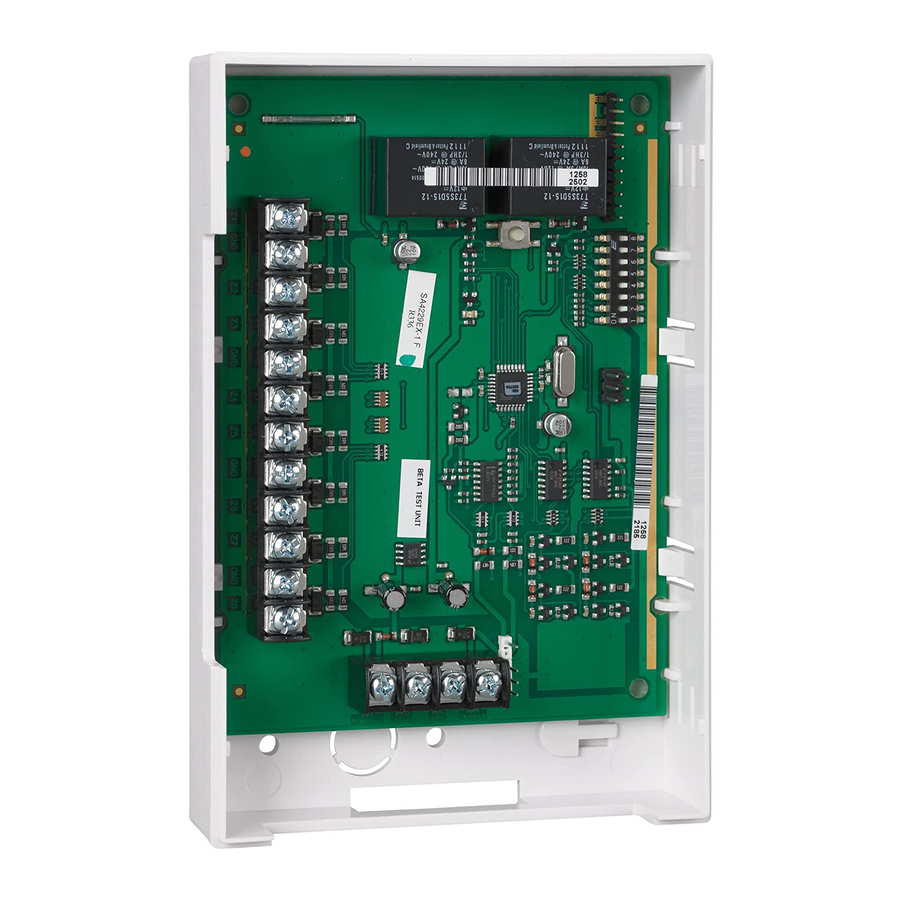
4229
Wired Zone Expander/Relay Module – Installation Instructions
GENERAL INFORMATION
The ADEMCO 4229 Wired Zone Expander/Relay Module
adds up to eight normally closed or eight end-of-line resistor
supervised zones and two dry form C (SPDT) relay outputs
to compatible control communicators via the control's
keypad wiring.
The module may be mounted within the control's cabinet (if
room permits), or remotely. If mounted remotely, there are
provisions to tamper-protect the unit. Communication to the
module is supervised so that it cannot be disconnected from
the keypad wiring without detection by the control. If the
wiring is cut, a tamper or alarm signal will result, to indicate
that this device (and possibly other similarly connected
devices) has become inoperative.
IMPORTANT: Some carbon monoxide detectors may not be
compatible with the ADEMCO 4229 hardwire zone
expanders. When using carbon monoxide detectors in
systems that support the 4229 zone expanders, install the
detectors only on the basic hardwire zones of the system
control panel, and NOT on the zone expanders.
INSTALLATION
When the module is to be mounted inside the control's
cabinet, it should be mounted horizontally.
tapping screws (provided) in two adjacent raised tabs at the
back of the cabinet. Leave the heads projecting 1/8". Hang
the module on the screw heads via two of the slotted holes
on the back of its housing. In this case, the module's cover
need not be tamper protected. See the control's instructions
for additional information.
When the module is to be mounted remotely, holes on its
back permit it to be mounted horizontally or vertically. Wires
can exit from the side or the breakout on the back of its
housing.
Place DIP switch #8 in the OFF position and,
when the installation is completed, the module's cover put
on. A magnet in the cover, positioned near a reed switch in
the unit, will cause a tamper signal to be sent to the control if
the cover is removed.
NOTE: For EN50131-3 compliance a tie-wrap must be
secured around the case of a remotely mounted 4229.
Apply tie-wrap around the case to the right of the large zone
wire opening (4-inch case width). This is in opposition of the
tamper switch and magnet.
Affix the connections label that accompanies the unit to the
inside of the module's cover (if the cover is to be used)) or to
the inside of the control's cover
CONNECTIONS AND SETTINGS
See the table and the diagram on the reverse side.
Zone Connections
Make protection zone connections to 12-position terminal
block TB1. Set DIP switch 7 for the desired zone operation
(NC or EOLR):
OFF = End of line resistor operation. Each zone that is
used must have a 2K-ohm end-of-line resistor
connected across the end of its loop, as shown in
Figure 2.
UL: Set to OFF (EOLR)
ON =
Normally closed operation
The method of programming each zone for type of alarm
and reporting code to the central monitoring station varies
with the control to which the module is connected. Refer to
the installation instructions for that control unit.
Module Address
Set the module address using DIP switches 2-6.
Select one of 31 addresses, as shown in the table on the
reverse side, so the control can identify the module and
communicate with it properly.
determined by the particular control to be used, and the
Insert self-
control's installation instructions must be consulted.
Normal/Fast Response Time for Zone A
Use DIP switch 1 to select normal or fast response time for
zone A:
OFF = fast response time of 10ms to an open circuit
ON =
normal response time of 300ms. All other module
protection zones have a nominal response time of
300ms.
Relay Connections
Connect the module's two relays to the appropriate devices
via the 7-conductor cord provided. Refer to the control's
installation instructions for specific information on how to
program the control's various activation options for the
relays.
Connection to the Control Panel
Connect the module to the control panel's keypad (ECP)
terminals via4-terminal block TB2 or the 4-pin plug (wire
color connections are the same).
SPECIFICATIONS
Physical
Electrical
Input Voltage:
Input Current:
Relay Contact
The address to be set is
6-7/16"W x 4-1/4"H x 1-1/4"D
(163mm x 108mm x 32mm)
12VDC (from control's remote keypad
connection points)
30mA (relays off)
100mA (relays on)
Rating:
2A max. at 28VDC/AC
Advertisement

Related Manuals for Honeywell ADEMCO 4229


Summary of Contents for Honeywell ADEMCO 4229
- Page 1 Wired Zone Expander/Relay Module – Installation Instructions GENERAL INFORMATION CONNECTIONS AND SETTINGS The ADEMCO 4229 Wired Zone Expander/Relay Module See the table and the diagram on the reverse side. adds up to eight normally closed or eight end-of-line resistor supervised zones and two dry form C (SPDT) relay outputs Zone Connections to compatible control communicators via the control’s...
- Page 2 Cet appareil ne doit pas causer d' interférences nuisibles. (2) Cet appareil doit accepter toute interférence reçue y compris les interférences causant une réception indésirable. ÊN8910V3VŠ 2 Corporate Center Drive, Suite 100 P.O. Box 9040, Melville, NY 11747 N8910V3 3/14 Rev. B Copyright © 2008 Honeywell International Inc.