Advertisement
Quick Links
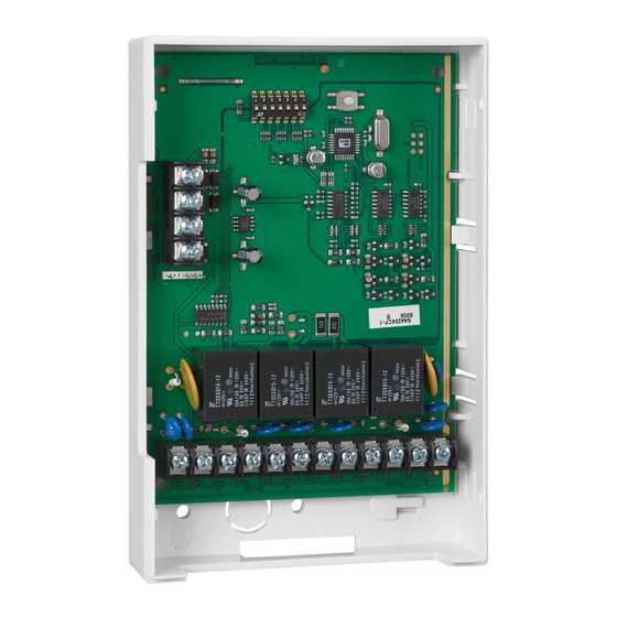
ADEMCO 4204 Relay Module – Installation Instructions
GENERAL INFORMATION
The ADEMCO 4204 Relay Module provides from one to four
dry, form-C (SPDT) relay outputs to compatible
control/communicators. It connects to the control's keypad
wiring terminals.
The 4204 can be mounted inside the control's cabinet or
mounted remotely depending on the application. Refer to the UL
notes below for certain restrictions.
If mounted remotely, the 4204 has a built-in tamper switch that
allows it to detect and report the removal of its cover to the
control. Second, communication to the 4204 is supervised so
that it cannot be disconnected from the keypad wiring without
detection by the control. If the wiring is cut, a tamper or alarm
signal will result, to indicate that this device (and possibly other
devices connected to the keypad wiring) has become
inoperative.
INSTALLATION
For UL Installations:
When used with controls that do not support cover tamper or
supervise communications wiring to the 4204, mount the 4204
inside the control's cabinet.
When used with controls that support cover tamper and
supervise communications wiring to the 4204, mount the 4204
may either be mounted inside the control's cabinet or mounted
remotely.
For dry, indoor use only. Do not install in air-
•
handling spaces.
For UL Commercial Burglary installations, the
•
4204 must be tamper protected or mounted in
UL
a tamper-protected cabinet.
In Commercial Fire applications, the module
•
cannot be mounted in the control unit's
cabinet, but must be mounted in an external
UL864-listed cabinet.
CUL
NOTE: The maintenance instructions shall detail all test
and maintenance instruction codes and software
necessary to provide test and inspection requirements
of CAN/ULC-S536, Standard for the Inspection and
Testing of Fire Alarm Systems
When mounted inside the control's cabinet, some controls allow
the 4204 to be mounted horizontally as follows: insert the self-
tapping screws (provided) in two adjacent raised tabs on the
back of the cabinet. Leave the heads projecting 1/8". Hang the
4204 on the screw heads via two of the slotted holes on the
back of its housing. The 4204's cover need not, in this case, be
tamper-protected. Set DIP switch 1 to "ON" if the cover is not
used (see table). See the control's instructions for additional
information.
When the 4204 is mounted remotely, it can be mounted
horizontally or vertically and the built-in tamper switch can be
used. Wires can exit from the side or via the breakout on the
back of its housing. The DIP switch must be set with its position
1 "OFF" and when the installation is completed, the unit's
tamper-protected cover must be replaced.
NOTE: For EN50131-3 compliance a tie-wrap must be secured
around the case of a remotely mounted 4204.
Apply tie-wrap around the case to the right of the large zone
wire opening (4-inch case width). This is in opposition of the
tamper switch and magnet.
NOTE: CE installations require maximum cable length of 30
meters.
Affix the connections label that accompanies the 4204 to the
inside of the 4204's cover (if the cover is used) or to the inside of
the control's cover.
CONNECTIONS AND SETTINGS
Select and set an address for the 4204, using its DIP switch as
shown in the DIP switch table. Each 4204 must be assigned a
unique address so the control can identify and communicate
with the 4204. The address to set is determined by the
particular control to be used. See the control's installation
instructions. As shipped, the DIP switch is set for address "0".
For UL fire installations, no more than
•
one wire per terminal may be
UL
connected.
Use only 14-22AWG wire.
•
NOTE: All power-limited wiring must be separated from non-
power limited wiring by ¼".
Make connections to the 4204's four relays via 12-position
terminal block TB2. Refer to the control's installation
instructions for specific information on how to program the
activation options for the relays.
Make connections to the control's keypad wiring points via 4-
position terminal block TB1, the 4-pin plug, or both (wire color
connections are the same). See the diagram on the other side
of this page.
SPECIFICATIONS
Physical: 6-7/16" W x 4-1/4" H x 1-1/4" D
(163mm x 108mm x 32mm)
Electrical:
Input Voltage:
12VDC nominal (10-14VDC, from
control's remote keypad connection
points)
Input Current:
15mA standby + 40mA per active relay
Contact Rating:
2A max. at 28VDC/AC (resistive loads)
Advertisement

Related Manuals for Honeywell ADEMCO 4204


Summary of Contents for Honeywell ADEMCO 4204
- Page 1 ADEMCO 4204 Relay Module – Installation Instructions GENERAL INFORMATION The ADEMCO 4204 Relay Module provides from one to four When the 4204 is mounted remotely, it can be mounted dry, form-C (SPDT) relay outputs to compatible horizontally or vertically and the built-in tamper switch can be control/communicators.
- Page 2 For the latest warranty information, please go to: www.honeywell.com/security/hsc/resources/wa Patents Warranty MyWebTech For patent information, see www.honeywell.com/patents 2 Corporate Center Drive, Suite 100 P.O. Box 9040, Melville, NY 11747 © Copyright 2008 Honeywell International Inc. N8909V5 1/17 Rev. A www.honeywell.com/security...