Cisco ASR 9901 Manual
Hide thumbs
Also See for ASR 9901:
- Hardware installation manual (158 pages) ,
- Installation manual (284 pages)
Table of Contents
Advertisement
Preparing for Installation
This chapter guides you through the process of preparing for router installation.
Before installing your Cisco ASR 9901 or Cisco ASR 9001 Router, you must consider these requirements:
• Power and cabling requirements must be in place at your installation site.
• Special equipment must be available for installing the router.
• The environmental conditions that your installation site must meet to maintain normal operation.
The shipping package for the router is engineered to reduce chances of product damage that may result from
routine material handling during shipment:
• Keep the router in the shipping container until you have determined the installation site.
• The router should always be transported or stored in its shipping package in the upright position.
Inspect all items for shipping damage. If an item appears damaged, contact a Cisco customer service
representative immediately.
This chapter contains these installation topics:
•
•
•
•
Overview
Cisco ASR 9901 Router
The Cisco ASR 9901 Router is a compact high-capacity provider edge (PE) router that delivers 456 Gbps of
non-blocking, full-duplex fabric capacity in a two-rack-unit (2RU) form factor.
Note
The Cisco ASR 9901 Router supports Cisco IOS XR 64-bit releases only.
Overview, on page 1
Safety Guidelines, on page 3
Site Requirement Guidelines, on page 6
Port Connection Guidelines, on page 35
Preparing for Installation
1
Advertisement
Table of Contents

Related Manuals for Cisco ASR 9901


Summary of Contents for Cisco ASR 9901
-
Page 1: Preparing For Installation
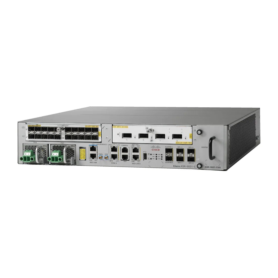
Port Connection Guidelines, on page 35 Overview Cisco ASR 9901 Router The Cisco ASR 9901 Router is a compact high-capacity provider edge (PE) router that delivers 456 Gbps of non-blocking, full-duplex fabric capacity in a two-rack-unit (2RU) form factor. Note The Cisco ASR 9901 Router supports Cisco IOS XR 64-bit releases only. - Page 2 Figure 1: Front Panel of the Cisco ASR 9901 Router Cisco ASR 9001 Router The Cisco ASR 9001 Router is a compact high-capacity provider edge (PE) router that delivers 120 Gbps of non-blocking, full-duplex fabric capacity in a two-rack-unit (2RU) form factor. Similar to other routers in the...
-
Page 3: General Safety Guidelines
Figure 3: Front Panel of the Cisco ASR 9001-S Router In order to achieve the full bandwidth of 120 Gbps and to enable the disabled ports, a Cisco license can be obtained. Once the license is obtained and installed, the Cisco ASR 9001-S Router must be reloaded to bring up the full 120 Gbps capacity. -
Page 4: Compliance And Safety Information
Statement 1051 Energy Hazard The Cisco ASR 9901 and Cisco ASR 9001 Router can be configured for a DC power source. Do not touch terminals while they are live. Observe this warning to prevent injury. -
Page 5: Lifting Guidelines
ASR 9001 Router Lifting Guidelines A fully-configured Cisco ASR 9901 can weigh as much as 55.97 pounds (25.4 kg). A fully-configured Cisco ASR 9001 Router can weigh as much as 37.91 pounds (17.2 kg). These systems are not intended to be moved frequently. -
Page 6: Site Requirement Guidelines
• To mount the router between two posts or rails, the usable aperture (the width between the inner edges of the two mounting flanges) must be at least 17.7 inches (45 cm) for the Cisco ASR 9001 Router and at least 17.75 inches (45.09 cm) for the Cisco ASR 9901 Router. - Page 7 Preparing for Installation Site Layout and Equipment Dimensions Figure 5: Cisco ASR 9901 Router Chassis Footprint and Dimensions Top View The following figure shows the top-down view chassis dimensions of the Cisco ASR 9001 Router. Preparing for Installation...
-
Page 8: Site Wiring Guidelines
Preparing for Installation Site Wiring Guidelines Figure 6: Cisco ASR 9001 Router Chassis Footprint and Dimensions Top View Site Wiring Guidelines When planning the location of the router, consider distance limitations for signaling, electromagnetic interference (EMI), and connector compatibility. If the wiring is run for any significant distance in an electromagnetic field, interference can occur between the field and the signals on the wires. -
Page 9: Chassis Air Flow Guidelines
Chassis Air Flow Guidelines Cisco ASR 9901 Router Cool air is circulated front-to-back through the Cisco ASR 9901 Router by three fan trays located in the rear of the router (see the following figure). The fan trays maintain acceptable operating temperatures for the internal components by drawing in cool air through the vents, and circulating the air through the chassis. - Page 10 Figure 7: Air Flow Path through the Cisco ASR 9901 Router Cisco ASR 9001 Router Cool air is circulated through the Cisco ASR 9001 Router by one fan tray located along the right side of the router (see the following figure).
-
Page 11: Rack-Mounting And Air Flow Clearance Guidelines
Preparing for Installation Rack-Mounting and Air Flow Clearance Guidelines Figure 8: Air Flow Path through the Cisco ASR 9001 Router When selecting a site to install the router, observe these guidelines: • Dust free area—Site should be as dust free as possible. Dusty environments can clog the power supply intake vents, reducing the cooling air flow through the router. -
Page 12: Telco 2-Post Rack
Cisco ASR 9901 Router The Cisco ASR 9901 Router can be installed in 19-inch or 23-inch (with extension adapter plates) telco-style racks. The chassis is supported by slide rails that are installed on the rear of the rack posts. Mounting brackets are installed on the sides of the chassis and are inserted along the slide rails. - Page 13 Note The mounting brackets on the Cisco ASR 9001 Router chassis have a pair of holes at the top and bottom of each bracket and three slots (elongated holes). If the Cisco ASR 9001 Router is to be mounted in a 2-post 19-inch rack, you must first use the holes to locate and position the brackets on the rack.
-
Page 14: Open 4-Post Rack
Two adjustable 4-post slide rails and two side-mounted guide brackets are provided for mounting the Cisco ASR 9901 Router in a 4-post rack. Two rear mounting brackets are provided for mounting the Cisco ASR 9001 Router in a 4-post rack. -
Page 15: Air Flow Guidelines For Enclosed Rack Installation
Air Flow Guidelines for Enclosed Rack Installation To install a Cisco ASR 9901 or Cisco ASR 9001 Router in an enclosed cabinet, the front and rear doors of the cabinet must be removed or be perforated with a minimum of 65% open area (70% for ETSI 800mm racks). -
Page 16: Temperature And Humidity Guidelines
Temperature and Humidity Guidelines Cisco ASR 9001 If you are mounting the Cisco ASR 9001 chassis in a 4-post enclosed cabinet, ensure that you have these clearances around the chassis: • Rear: Minimum of 3.15 inches (8.00 cm) of clearance •... -
Page 17: Power Connection Guidelines
National Electrical Code (NEC) as well as local codes. Caution Each Cisco ASR 9901 or Cisco ASR 9001 Router is powered by only one type of input: AC or DC. A hybrid (AC+DC) power configuration is not supported. - Page 18 Preparing for Installation AC Powered Routers Locale Part Number Length Power Cord Rating Europe CAB-AC-16A-SG-EU 14 ft (4.26 16A, 250 VAC India CAB-AC-16A-SG-IND 14 ft (4.26 16A, 250 VAC International/UK CAB-AC-16A-SG-IN 14 ft (4.26 16A, 250 VAC Israel CAB-AC-16A-SG-IS 14 ft (4.26 16A, 250 VAC Italy CAB-AC-16A-SG-IT...
- Page 19 Preparing for Installation AC Powered Routers AC Power Cord Illustrations for Cisco ASR 9901 Router This section contains the AC power cord illustrations, as described in the above table. Note that an AC power cord may be used with several power supplies.
- Page 20 Preparing for Installation AC Powered Routers Figure 17: CAB-AC-16A-SG-CH Power Cord Figure 18: CAB-AC-16A-SG-EU Power Cord Figure 19: CAB-AC-16A-SG-IND Power Cord Preparing for Installation...
- Page 21 Preparing for Installation AC Powered Routers Figure 20: CAB-AC-16A-SG-IN Power Cord Figure 21: CAB-AC-16A-SG-IS Power Cord Figure 22: CAB-AC-16A-SG-IT Power Cord Preparing for Installation...
- Page 22 Preparing for Installation AC Powered Routers Figure 23: CAB-AC-16A-SG-JPN Power Cord Figure 24: CAB-AC-16A-SG-SA Power Cord Figure 25: CAB-AC-16A-SG-SW Power Cord Preparing for Installation...
- Page 23 Preparing for Installation AC Powered Routers Figure 26: CAB-AC-16A-SG-UK Power Cord Figure 27: CAB-AC-20A-SG-US Power Cord Figure 28: CAB-AC-20A-SG-US1 Power Cord Preparing for Installation...
- Page 24 Preparing for Installation AC Powered Routers Figure 29: CAB-AC-20A-SG-US2 Power Cord Figure 30: CAB-AC-20A-SG-US3 Power Cord Figure 31: CAB-AC-20A-SG-US4 Power Cord Preparing for Installation...
- Page 25 Preparing for Installation AC Powered Routers Figure 32: CAB-AC-20A-SG-C20 Power Cord Figure 33: CAB-HV-25A-SG-US2 Power Cord Figure 34: CAB-HV-25A-SG-IN2 Power Cord Preparing for Installation...
- Page 26 AC Input Voltage Range. The following table lists the AC-input power cord options, specifications, and Cisco product numbers for the Cisco ASR 9001 AC-input power supply modules. This table also references power cord illustrations. For more information on Cisco product numbers (PIDs) and their detailed description of power cords, refer to Dynamic Configuration Tool.
- Page 27 8.2 feet (2.5 m) 10 A, 250 V AC Power Cord Illustrations for Cisco ASR 9001 Router This section contains the AC power cord illustrations, as described in the above table. Note that an AC power cord may be used with several power supplies.
- Page 28 Preparing for Installation AC Powered Routers Figure 39: AC Power Cord CAB-ACI Figure 40: AC Power Cord CAB-ACR Figure 41: AC Power Cord CAB-ACS Preparing for Installation...
- Page 29 Preparing for Installation AC Powered Routers Figure 42: AC Power Cord CAB-ACU Figure 43: AC Power Cord CAB-ACC Figure 44: AC Power Cord CAB-ACSA Preparing for Installation...
-
Page 30: Dc Powered Router
The length of the cables depends on your router location from the source power. Note DC power cables are not available from Cisco, but they are available from external commercial cable vendors. You must terminate DC power cables using terminal blocks. The terminal blocks are supplied along with the DC power supply modules from Cisco. - Page 31 Preparing for Installation DC Powered Router Figure 47: Cisco ASR 9901 DC Power Cable Terminal Block Figure 48: Cisco ASR 9001 DC Power Cable Terminal Block The figure below shows DC power source cable connections for single DC power module.
- Page 32 Preparing for Installation DC Powered Router Figure 49: Cisco ASR 9901 DC Power Source Cabling Scheme for a Single DC Power Module Preparing for Installation...
- Page 33 DC Powered Router Figure 50: Cisco ASR 9001 DC Power Source Cabling Scheme for a Single DC Power Module The color coding of the source DC power cable leads depends on the color coding of the site DC power source.
-
Page 34: Nebs Supplemental Unit Bonding And Grounding Guidelines
AC power modules. The following figures show the NEBS grounding locations for the Cisco ASR 9901 Router and Cisco ASR 9001 Router. -
Page 35: Port Connection Guidelines
Preparing for Installation Port Connection Guidelines Figure 52: NEBS Bonding and Grounding Points on the Cisco ASR 9001 Router NEBS grounding point on side of chassis To ensure a satisfactory supplemental ground connection to the router, use these parts: • One grounding lug, which has two M6 bolt holes with 0.625- to 0.75-inch (15.86- to 19.05-mm) spacing between them, and a wire receptacle large enough to accept a six AWG or larger, multistrand copper wire. - Page 36 Preparing for Installation Port Connection Guidelines Figure 53: Cisco ASR 9901 Router Front Panel Ports SYNC (BITS/J.211) ports External USB port Service LAN and ToD 10MHz and 1PPS ports ports CONSOLE and AUX Nine discrete LED ports indicators Management LAN ports...
- Page 37 Port Connection Guidelines Note In Cisco ASR 9001-S Router, two 10 GE fixed SFP+ ports (SFP+2 and SFP+3) are disabled by default, and can be enabled by a license upgrade. The following table lists the Cisco ASR 9901 and Cisco ASR 9001 Router front panel ports description.
-
Page 38: Console Port And Auxiliary Port Connection Guidelines
Signal type is NRZI. CLUSTER Ports (0/1) For Cascading two Cisco ASR 9001 Router systems. The pinout and signal level is as per the SFP standard. (Cisco ASR 9001 Router This supports copper/optical SFP modules. -
Page 39: Auxiliary Port Signals
Preparing for Installation Auxiliary Port Signals Console Port Pin Signal Input/Output Description Input Receive data — — (Not connected) Input Clear to Send Auxiliary Port Signals The RP Auxiliary (AUX) port is a RJ-45 interface for connecting a modem or other data communication equipment (DCE) device (such as another router) to the RP. -
Page 40: Management Lan Port Led Indicators
Preparing for Installation Management LAN Port LED Indicators • Autonegotiation of port speed (10/100/1000) and duplex (full/half) is supported. Autonegotiation cannot be disabled. The following table lists the signals used on the Management LAN ports. Table 6: RP Management LAN Port Signals MGT LAN Port Pin 10Base-T, 100Base-TX Signal 1000Base-T Signal... -
Page 41: Sync Ports Connection Guidelines
Preparing for Installation Sync Ports Connection Guidelines Note To comply with the intra-building lightning surge requirements of Telecordia GR-1089-CORE, Issue II, Revision 01, February 1999, you must use a shielded cable when connecting the management LAN ports on the RP card. The shielded cable is terminated by shielded connectors on both ends, with the cable shield material tied to both connectors. -
Page 42: Rp External Usb Port
RP External USB Port The Cisco ASR 9901 Router and Cisco ASR 9001 Router has an external USB Type A slot accessible on the front panel. The front panel USB slot accepts widely available USB thumb drives. The only restriction on devices you can plug into the front panel external USB slot is that they need to be USB 2.0 devices. - Page 43 Preparing for Installation RP External USB Port Note Do not connect a USB hub device to the front panel USB port. Preparing for Installation...
- Page 44 Preparing for Installation RP External USB Port Preparing for Installation...