Cisco ASR-920-12SZ-IM Quick Start Manual
Aggregation services router
Hide thumbs
Also See for ASR-920-12SZ-IM:
- Hardware installation manual (118 pages) ,
- Getting started (6 pages)

Related Manuals for Cisco ASR-920-12SZ-IM


Summary of Contents for Cisco ASR-920-12SZ-IM
-
Page 1: Table Of Contents
Cisco ASR-920-12SZ-IM and ASR-920-U-12SZ-IM Aggregation Services Router Quick Start Guide Cisco ASR-920-12SZ-IM and ASR-920U-12SZ-IM Aggregation Services Router Quick Start Guide Overview Installing the Router in a Rack Configuring the Router at Startup Related Documents... -
Page 2: Cisco Asr-920-12Sz-Im And Asr-920U-12Sz-Im Aggregation Services Router Quick Start Guide
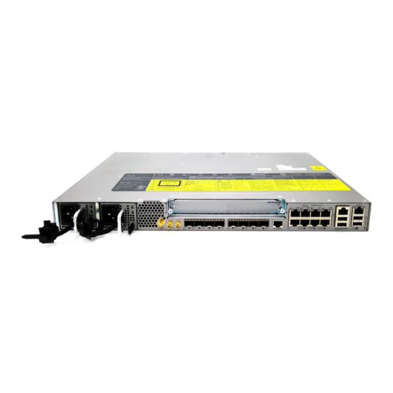
Router in this document. Any differences between the routers are specifically called out. The Cisco ASR 920 Series Aggregation Services Router is a family of fixed configuration routers that provides common network architecture to the Service Providers for macro and small cell networks. - Page 3 Figure 2: Front Panel of Cisco ASR-920-12SZ-IM Router With AC Power Supply Power Supply 0 (AC or DC) Alarm port Power Supply 1 (AC or DC) Eight Copper port (1G PoE) Note Port 0 is located at the bottom right, port 1 is located at the top right, and so on.
- Page 4 Figure 3: Rear View of Cisco ASR-920-12SZ-IM Router Fan tray Air vents Grounding lug — The following table describes the other features of Cisco ASR-920-12SZ-IM (AC and DC) Router. Table 1: Cisco ASR-920-12SZ-IM Router Specifications Specification ASR-920-12SZ-IM DimensionWidth x Depth x Height 17.5 x 9.88 x 1.73 inches...
- Page 5 • LED indicators for critical, major, and minor alarms Supported Interface Modules For more information on these IM modules, see the Cisco ASR 903 Aggregation Series Router Hardware Installation Guide. For more information on the supported IMs, see the Cisco ASR920 Data sheet.
- Page 6 Figure 4: Cisco ASR-920-12SZ-IM Router Dimensions External Interfaces The external physical interfaces on the front panel of the router are: • Network Interfaces • Network Timing Interfaces • External Alarm Inputs • Management Interfaces • Mangement ENET Port • RS232 Console Port •...
- Page 7 Note If only one PSU is present, a successful firmware upgrade to either primary or secondary microcontroller unit (MCU) triggers a reload of device and is reloaded before any warning messages are displayed. Table 2: Power Supply Specification Specification AC (A920-PWR400-A) DC (A920-PWR400-D) Input Voltage 85–264, nominal 100VAC, 240VAC...
-
Page 8: Installing The Router In A Rack
Cisco software feature sets by obtaining and validating fee-based Cisco software licenses. Note Licenses generated by the Cisco Software Licensing are tied to the UDI of the chassis and a corresponding watchtower device certificate (WDC) is stored in the system. - Page 9 Attaching Brackets for 19-Inch Racks The following figure shows how to attach brackets for 19-inch racks on the router. Figure 5: Attaching Brackets for 19-Inch Racks Phillips flat-head screws Front-mounting position...
- Page 10 Ensure that the rack-mount brackets are securely fastened. For more information, see the Attaching Brackets to the Router section in the Cisco ASR-920-12SZ-IM and ASR-920U-12SZ-IM Aggregation Services Router Hardware Installation Guide.
- Page 11 • If the rear of the chassis is at the front of the rack, insert the front of the chassis between the mounting posts. Step 2 Align the mounting holes in the bracket (and optional cable guide) with the mounting holes in the equipment rack. The following figure shows how to install the router in a 19-inch EIA rack.
- Page 12 Procedure Step 1 Attach an ESD-preventive wrist strap to your wrist and to a bare metal surface on the chassis. Some SFP modules identify the top side of the module with send (TX) and receive (RX) markings or arrows that show the direction of the connection.
- Page 13 This section describes how to ground the chassis. The grounding lug location is on the back panel of the router. Ensure that the grounding lug wire does not cover the fan opening. Figure 9: Attaching a Grounding Lug to the Rear of the Router Grounding-lug To ensure that the chassis ground connection that you provide is adequate, you need the following parts and tools: •...
- Page 14 Perform the following procedure to ground the router using a 2-hole lug and the corresponding mounting point. Most carriers require a minimum 6-AWG ground connection. Verify your carrier’s requirements for the ground connection. Procedure Step 1 If your ground wire is insulated, use a wire-stripping tool to strip the ground wire to 0.5 inch ± 0.02 inch (12.7 mm ±0.5 mm).
- Page 15 Caution Always wear the ESD wrist strap when installing or uninstalling the fan tray. Caution Unplug all power sources before performing this procedure. Procedure Step 1 Orient the fan tray so that the captive screws are aligned to the chassis cavity on the back panel. See the following figure. Figure 12: Installing the Fan Tray in the Chassis Step 2 Push the fan assembly into the chassis until the power connector seats in the backplane and the captive installation screws...
- Page 16 Installing an Interface Module Caution Before inserting an interface module, make sure that the chassis is grounded. Procedure Step 1 To insert the interface module, carefully align the edges of the interface module between the upper and lower edges of the router slot.
- Page 17 Figure 13: Installing the DC Power Supply Module Activate a DC Power Supply Module Perform the following procedure to activate a DC power supply: Procedure Step 1 Remove the tape from the circuit-breaker router handle, and restore power by moving the circuit-breaker router handle to the On (|) position.
- Page 18 Figure 14: Attach the AC Power Tie-and-Clip Cord Note These images are for only representation purposes. Certain variants of Cisco NCS 540 do not include a tie for the power supply cord. Activate an AC Power Supply Module...
- Page 19 Install the USB device driver before establishing a physical connection between the router and the PC, by using the USB console cable plugged into the USB serial port. Otherwise, the connection will fail. For more information, see the Installing the Cisco USB Device Driver section in the Cisco ASR-920-12SZ-IM and ASR-920U-12SZ-IM Aggregation Services Router Hardware Installation Guide.
-
Page 20: Configuring The Router At Startup
To configure a Cisco ASR 920 Series Router from the console, you must connect a terminal or terminal server to the console port on the Cisco ASR 920 Series Router. To configure the router using the management Ethernet port, you must have the router’s IP address. - Page 21 Router> Step 3 From the user EXEC mode, enter the enable command, as shown in the following example: Example: Router> enable Step 4 At the password prompt, enter your system password, as shown in the following example. If an enable password has not been set on your system, you can skip this step.
- Page 22 After confirming the reload command, wait until the system bootstrap message is displayed before powering off the system: Example: System Bootstrap, Version 15.4(3)S1, RELEASE SOFTWARE (fc1) Technical Support: http://www.cisco.com/techsupport Copyright (c) 2012 by cisco Systems, Inc. Current image running: Boot ROM0...
-
Page 23: Related Documents
Note After powering off the router, wait for a minimum of 30 seconds before powering it on again. Related Documents • Cisco ASR 920 and ASR 920U Aggregation Services Router Hardware Installation Guide can be viewed at: https://www.cisco.com/ c/en/us/td/docs/routers/asr920/hardware/installation/guide-12sz-im/b-asr-920-12-SZ-IM.html. • The documentation for the supported software features can be viewed at https://www.cisco.com/c/en/us/support/routers/... - Page 24 Cisco has more than 200 offices worldwide. Addresses and phone numbers are listed on the Cisco website at www.cisco.com/go/offices. Cisco and the Cisco logo are trademarks or registered trademarks of Cisco and/or its affiliates in the U.S. and other countries. To view a list of Cisco trademarks, go to this URL: https://www.cisco.com/c/en/us/about/legal/trademarks.html.
- Page 25 Cisco Systems, Inc. CiscoSystems(USA)Pte.Ltd. CiscoSystemsInternationalBV San Jose, CA 95134-1706 Singapore Amsterdam,TheNetherlands Cisco has more than 200 offices worldwide. Addresses, phone numbers, and fax numbers are listed on the Cisco Website at www.cisco.com/go/offices. © 2020 Cisco and/or its affiliates. All rights reserved.