Cisco ASR 903 Quick Start Manual
Aggregation services router
Hide thumbs
Also See for ASR 903:
- Release notes (280 pages) ,
- Installation manual (200 pages) ,
- Hardware installation manual (196 pages)
Table of Contents
Advertisement
Quick Links
Advertisement
Table of Contents

Related Manuals for Cisco ASR 903


Summary of Contents for Cisco ASR 903
- Page 1 Cisco ASR 903 and ASR 903U Aggregation Services Router Quick Start Guide...
-
Page 2: Quick Start Guide
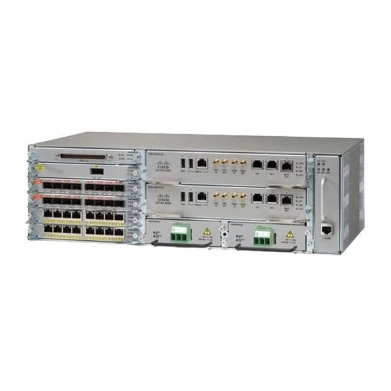
Overview The Cisco ASR 903 and the Cisco ASR903U routers expands the Cisco service provider product portfolio by providing a rich and scalable feature set of Layer 2 VPN (L2VPN) and Layer 3 VPN (L3VPN) services in a compact package. It also supports a variety of software features, including Carrier Ethernet features, Timing over Packet, and pseudowire. -
Page 3: Power Supply Features
Dying Gasp The Cisco ASR 903 Router DC power supply supports the Dying Gasp feature, which allows the router to provide an input power loss notification to the RSP so that the RSP can send appropriate SNMP traps or OAM messages and update log files on the router. -
Page 4: Rsp Modules
RSP Modules The Cisco ASR 903 Router is designed to use up to two RSP modules to handle the data plane, network timing, and control plane functionalities for the router. The RSP configuration allows you to use Cisco IOS software to control chassis management, redundancy, external management, and system status indications on the router. -
Page 5: Gnss Module (A900-Cm-Gnss)
RSP Redundancy The Cisco ASR 903 Router chassis includes two RSP slots to allow for redundant RSPs. When the router uses redundant RSPs, one RSP operates in the active mode and the other operates in the hot standby mode. Removal or failure of the active RSP results in an automatic switchover to the standby RSP. -
Page 6: Interface Modules
The splitter should have all the RF ports capable of DC-pass, if the antenna needs to feed power from Note GNSS module. Interface Modules The Cisco ASR 903 Router interface modules are a field-replaceable units. In addition to the ports provided on an RSP, the Cisco ASR 903 Router supports the following interface modules:... -
Page 7: Installing The Router In A Rack
Remove the rack-mount brackets from the accessory kit and position them beside the router chassis. The figure below hows how to attach the brackets on the Cisco ASR 903 Router for a 19-inch EIA rack. Figure 2: Attaching Mounting Brackets for a 19-inch EIA Rack... -
Page 8: Installing The Router Chassis In The Rack
The figure below shows how to attach the brackets on the Cisco ASR 903 Router for a 300 mm ETSI cabinet. Figure 3: Attaching Mounting Brackets for a 300 mm ETSI Cabinet Step 2 Position one of the brackets against the chassis side, and align the screw holes. -
Page 9: Installing The Chassis Ground Connection
Use a tape measure and level to verify that the chassis is installed straight and level. Installing the Chassis Ground Connection Before you connect the power or turn on the power to the Cisco ASR 903 Router, you must provide an adequate chassis ground (earth) connection to your router. - Page 10 Grounding lug (19-inch EIA rack) Before making connections to the router, ensure that you disconnect the power at the circuit breaker. Caution Otherwise, severe injury to you or damage to the router may occur. This equipment must be grounded. Never defeat the ground conductor or operate the equipment in the Warning absence of a suitably installed ground conductor.
-
Page 11: Installing The Fan Tray
Connect the other end of the ground wire to a suitable grounding point at your site. Installing the Fan Tray The fan tray is a modular unit that provides cooling to the Cisco ASR 903 Router. Follow these steps to install the fan tray in the chassis:... -
Page 12: Installing An Rsp Module
Secure the fan tray to the chassis using the attached captive installation screws. The recommended maximum torque is 5.5 in.-lb (.62 N-m). This completes the procedure for installing or replacing the fan tray in a Cisco ASR 903 Router. Installing an RSP Module... - Page 13 Close all unused RJ-45 and USB ports on the RSP module using the appropriate dust caps to prevent dust from Note accumulating inside the cage. For information on dust caps, see Installing Dust Caps section in the Cisco ASR 903 and ASR 903U Aggregation Services Router Hardware Installation Guide.
-
Page 14: Installing An Interface Module
For information on dust caps, see Installing Dust Caps section in the Cisco ASR 903 and ASR 903U Aggregation Services Router Hardware Installation Guide. Do not use interface module and power supply ejector handles to lift the chassis; using the handles to lift the Caution chassis can deform or damage the handles. -
Page 15: Installing The Dc Power Supply Module
◦ 900 W DC power: –40VDC to –72VDC The DC power supply provides option to connect with two different sources (dual feed); positive (+) and negative (-) are marked on the PSU terminals. Each power supply provides a dual primary input power connection. Caution The power supply must be wired before plugging the power supply in the chassis. - Page 16 Step 1 Ensure that the system (earth) ground connection has been made. For ground connection installation instructions, see Installing the Chassis Ground Connection section in the Cisco ASR 903 and ASR 903U Aggregation Services Router Hardware Installation Guide. Step 2 If necessary, remove the blank power supply filler plate from the chassis power supply bay opening by loosening the captive installation screws.
- Page 17 Step 1 Ensure that the system (earth) ground connection has been made. For ground connection installation instructions, see Installing the Chassis Ground Connection section in the Cisco ASR 903 and ASR 903U Aggregation Services Router Hardware Installation Guide. Step 2 If necessary, remove the blank power supply filler plate from the chassis power supply bay opening by loosening the captive installation screws.
-
Page 18: Connecting The Cisco Asr 903 Router To The Network
Power supply captive installation screws must be tight to ensure protective grounding continuity. Warning Connecting the Cisco ASR 903 Router to the Network When installing the cabling to the RSPs, we recommend that you leave a service loop of extra cabling Note sufficient to allow for fan tray removal. -
Page 19: Connecting Console Cables
Cisco ASR 903 and ASR 903U Aggregation Services Router Hardware Installation Guide. When the USB port is used it takes priority over the RJ45 EIA port. The USB Type A-to-Type A cable is not included with the Cisco ASR 903 Router; it is ordered separately. Note Step 2 Connect the end of the cable with the DB-9 connector (or USB Type-A) to the terminal or PC. - Page 20 • no flow control Figure 14: Connecting the USB Console Cable to the Cisco ASR 903 Router USB Type-A console port USB Type-A to USB Type-A Console cable USB Type-A — —...
-
Page 21: Powering Up The Cisco Asr 903 Router
Procedure Step 1 Activate the DC power supply as described in the Activating the DC Power Supply section in the Cisco ASR 903 and ASR 903U Aggregation Services Router Hardware Installation Guide. Do not press any keys on the keyboard until the messages stop and the SYS PWR LED is solid green. Any... - Page 22 "License Notice" file accompanying the IOS-XE software, or the applicable URL provided on the flyer accompanying the IOS-XE software. A summary of U.S. laws governing Cisco cryptographic products may be found at: http://www.cisco.com/wwl/export/crypto/tool/stqrg.html If you require further assistance please contact us by sending email to export@cisco.com.
-
Page 23: Verifying The Front Panel Leds
The front-panel indicator LEDs provide power, activity, and status information useful during bootup. For more detailed information about the LEDs, see Troubleshooting in the Cisco ASR 903 and ASR 903U Aggregation Services Router Hardware Installation Guide. Verifying the Hardware Configuration To display and verify the hardware features, enter the following commands: •... -
Page 24: Checking Hardware And Software Compatibility
For information on modifying the configuration after you create it, see the Cisco IOS configuration and command reference guides. To configure a Cisco ASR 903 Router from the console, you must connect a terminal or terminal server to the console port on the Cisco ASR 903 Router RSP. -
Page 25: Configuring Global Parameters
Rights clause at FAR sec. 52.227-19 and subparagraph (c) (1) (ii) of the Rights in Technical Data and Computer Software clause at DFARS sec. 252.227-7013. cisco Systems, Inc. 170 West Tasman Drive San Jose, California 95134-1706 --- System Configuration Dialog ---... -
Page 26: Related Documents
Basic management setup configures enough connectivity for managing the system; extended setup will ask you to configure each interface on the system. For detailed information about setting global parameters, refer to the Cisco ASR 903 Router Software Configuration Guide. - Page 27 Cisco and the Cisco logo are trademarks or registered trademarks of Cisco and/or its affiliates in the U.S. and other countries. To view a list of Cisco trademarks, go to this URL: www.cisco.com/go/trademarks . Third-party trademarks mentioned are the property of their respective owners. The use of the word partner does not imply a partnership relationship between Cisco and any other company.
- Page 28 Cisco Systems, Inc. Cisco Systems (USA) Pte. Ltd. Cisco Systems International BV San Jose, CA 95134-1706 Singapore Amsterdam, The Netherlands Cisco has more than 200 offices worldwide. Addresses, phone numbers, and fax numbers are listed on the Cisco Website at www.cisco.com/go/offices.