Advertisement
Available languages
Available languages
Quick Links
BEFORE INSTALLATION
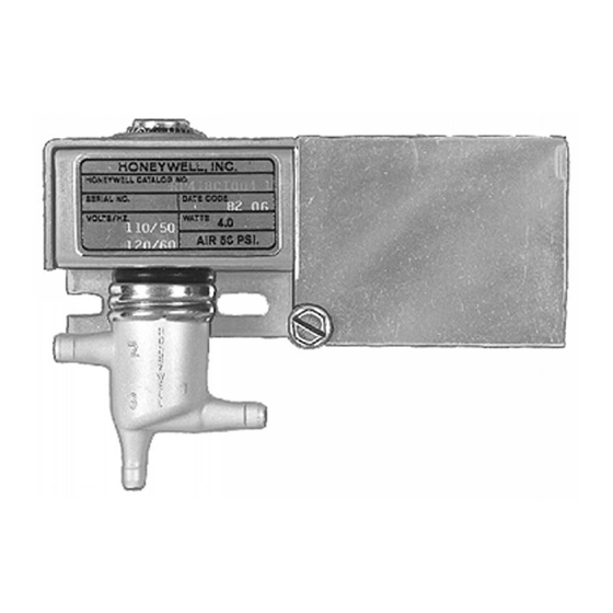
The RP418 and RP818 Electric/Pneumatic Relays are
electrically operated pneumatic switches used for interlock
between an electrical system and a pneumatic control system.
These devices can also be used as stop and bleed valves or
as diverting or selector relays.
These relays are designed for wall mounting or panel
mounting, depending upon the application. They can be
mounted in any position without affecting the operation of the
device.
An optional 14003638-001 mounting kit is available for direct
mounting to the MP516A operators, VP519C valves or
PP901B and PP902B pressure regulators. See the Device
Mounting section.
No special tools are needed to install the RP418 and RP818
relays. Refer to job drawings for specific mounting locations.
INSTALLATION
Duct or Wall Mounting
1. Position the relay on the duct or wall and mark the
knockout mounting holes or mark the first hole and
measure 1 in. (25mm) to the second hole. See Fig. 1.
2. Drill holes for no. 8 mounting screws obtained locally.
NOTE: When wall mounting, use the mounting holes on the
sides of the relay valve body or the knockout mount-
ing holes on the inside of the splice box. See Fig. 2.
3. Attach the relay to the panel using mounting screws
obtain locally.
Panel Mounting
1. Line up the no. 8 mounting holes on the sides of the
valve body with existing holes in the panel or drill new
holes 1 in. (25 mm) apart.
2. Attach the relay to the panel using mounting screws
obtained locally.
® U.S. Registered Trademark
Copyright © 2002 Honeywell • All Rights Reserved
RP418A, B, C and RP818A, B
Electric/Pneumatic Relays
NOTE: The RP418 and RP818 are functional replacements
2-3/4
Device Mounting
The RP418 and RP818 Relays can be mounted directly to
MP516 operators, VP519C valves, or PP901B and PP902B
pressure regulators. A mounting bracket is available in
adaptor kit 14003638-001. This bracket must be used when
mounting the relay in this manner.
1. Use the mounting holes beneath the cover of the splice
INSTALLATION INSTRUCTIONS
for the RP417 and RP817. Note the difference in
location of ports 1 and 2.
3-3/4 (96)
RP418A,C AND RP818A
1-5/8 (42)
RP418B; RP818B
GROUNDING
SCREW
(71)
1-1/4
(32)
1-1/4
(32)
7/16
(15)
1 (25)
1
1
1
MOUNTING CENTERS FOR NO. 8 SCREWS. MOUNTING CENTERS
MAY BE UP TO 1-5/16 (35) APART TO EASE INSTALLATION.
Fig. 1. RP418 and RP818 dimensions in in. (mm).
box and attach the relay using mounting screws
obtained locally. See Fig. 2 through 5.
7/8 DIAMETER
KNOCKOUTS (2)
FOR 1/2 INCH
CONDUIT
1 (25)
5/8 (16)
KNOCKOUTS FOR
NO. 8 SCREWS
1-3/8
(35)
M18376
95-6046EF
Advertisement

Related Manuals for Honeywell RP418B


Summary of Contents for Honeywell RP418B
- Page 1 2. Attach the relay to the panel using mounting screws box and attach the relay using mounting screws obtained locally. obtained locally. See Fig. 2 through 5. ® U.S. Registered Trademark Copyright © 2002 Honeywell • All Rights Reserved 95-6046EF...
- Page 2 Make the wire splices within the electrical box. Fig. 6. RP418 and RP818 typical wiring and piping. Wire leads provide a means of connection on the RP418B and RP818B. Use standard wire nut connectors, obtained locally, when making these connections.
- Page 3 à 25 mm (1 po) de distance l'un de l'autre. 2. Fixer le relais sur le panneau au moyen de vis de mon- tage, non fournies. ® U.S. Registered Trademark Copyright © 2002 Honeywell • All Rights Reserved 95-6046EF...
- Page 4 Fig. 7. Schéma de raccordement pneumatique. Le RP418 et le RP818 ne nécessitent ni réglage ni étalonnage. Solutions de régulation et d’automatisation Honeywell Honeywell Limited-Honeywell Limitée 1985 Douglas Drive North 35, Dynamic Drive Golden Valley, MN 55422 Scarborough (Ontario) M1V 4Z9 Imprimé...