Table of Contents
Advertisement
JANOME ELECTRO PRESS
JP-104
JP-1504
JPH-104
JPH-1504
JPU-104
JPU-1504
Operation Manual
"For Qualified Installer ONLY"
Thank you for purchasing the Electro Press.
*Read this manual thoroughly in order to properly use this machine.
Be sure to read "For Your Safety" before you use the machine. It
will protect you from possible dangers during operation.
*After having read this manual, keep it in a handy place so that you
or the operator can refer to it whenever necessary.
JP-204
JP-3004
JPH-204
JPH-3004
JPU-204
JPU-3004
<Setup>
JP-504
JP-5004
JPH-504
JPH-5004
JPU-504
JPU-5004
JP-1004
JPH-1004
JPU-1004
JPU-8004
Advertisement
Table of Contents

Related Manuals for Janome JP-104


Summary of Contents for Janome JP-104
- Page 1 JANOME ELECTRO PRESS JP-104 JP-204 JP-504 JP-1004 JP-1504 JP-3004 JP-5004 JPH-104 JPH-204 JPH-504 JPH-1004 JPH-1504 JPH-3004 JPH-5004 JPU-104 JPU-204 JPU-504 JPU-1004 JPU-1504 JPU-3004 JPU-5004 JPU-8004 Operation Manual <Setup> “For Qualified Installer ONLY” Thank you for purchasing the Electro Press. *Read this manual thoroughly in order to properly use this machine.
-
Page 2: For Your Safety
FOR YOUR SAFETY Safety Precautions The precautions stated in this manual are provided for the customer to make the best use of this product safely, and to provide preventive measures against injury to the customer or damage to property. ・・・・・Be sure to follow the instructions・・・・・ Various symbols are used in this manual. - Page 3 FOR YOUR SAFETY Warnings Do not leave the unit plugged in (power cord and connectors) when it is not in use for long periods of time. Dust can cause fire. Be sure to shut off the power supply before removing the power cord. Regularly replace the built-in battery (optional) in the body or control box.
- Page 4 FOR YOUR SAFETY INSTALLATION Warnings Install an interlock as a safeguard that triggers an emergency stop when it is activated using the I/O-S connector included in the package. <Example> Use protective wear (helmet, protective gloves, protective glasses and protective footwear) when installing the machine. Place the machine in a well-ventilated area for the health and safety of the operator.
- Page 5 FOR YOUR SAFETY Warnings Confirm that the unit is properly grounded. Power supply earth should be connected complying with Type D grounding. (under 100 Ω of resistance.) Insufficient grounding can cause electric shock, fire or malfunction. Plug the power cord into the wall outlet firmly. Incomplete insertion into the wall outlet heats the plug and can cause fire.
- Page 6 FOR YOUR SAFETY Warnings Use the machine in an environment where no electric noise is present. Attach an eyebolt and use a crane or other equipment to transport the machine. Failure to do so may result in malfunction or defect. Do not bump or jar the machine while it is being transported or installed.
- Page 7 FOR YOUR SAFETY WORKING ENVIRONMENT Warnings When you lubricate or inspect the unit, unplug the power cord from the outlet. Failure to do so may result in electric shock or injury. Be sure to shut off the power supply before removing the power cord. During operation, always have the emergency stop switch within the operator’s reach.
- Page 8 FOR YOUR SAFETY DURING OPERATION Warnings When starting the machine, check that no object will interfere with the machine’s operation. Under no circumstances should you go inside the working area or place your hands or head inside the working area while the machine is operating.
-
Page 9: Preface
PREFACE The operation manual for the JANOME Electro Press consists of the following volumes. “For Your Safety” is also provided so that the customer can make the best use of this product safely. This section includes preventive measures that can be taken against injury to the customer or damage to property. -
Page 10: Table Of Contents
2-3 Unit Type__________________________________________________________________ 5 3. INSTALLATION _______________________________________________________________ 6 3-1 Lifting ____________________________________________________________________ 6 3-2 Setting____________________________________________________________________ 9 3-2-1 JP-104/JP-204, Stand-Alone Type ___________________________________________ 9 3-2-2 JP-504/JP-1004/JP-1504, Stand-Alone Type__________________________________ 10 3-2-3 JP-3004/JP-5004, Stand-Alone Type _________________________________________11 3-2-4 JPH-104/JPH-204, Head Type_____________________________________________ 12 3-2-5 JPH-504/JPH-1004, Head Type____________________________________________ 13... - Page 11 3-5 Ram Mounting Jig__________________________________________________________ 28 3-5-1 JP, JPH, JPU-104/204 ___________________________________________________ 28 3-5-2 JP, JPH, JPU-504/1004/1504______________________________________________ 29 3-5-3 JP, JPH, JPU-3004/5004, JPU-8004 ________________________________________ 30 3-5-4 Switching I/O-SYS and I/O-1 Power Supply___________________________________ 31 3-6 Safeguard Installation _______________________________________________________ 32 4. HOW TO BACK UP UNIQUE NUMBER AND INSTALL SETTING DATA __________________ 35 5.
-
Page 12: Environment
1. ENVIRONMENT ■ Place the machine on a suitable flat surface that can support its weight. Be sure to leave a space greater than 30cm between the back of the control box equipped with a cooling fan and the wall. Do not cover the cooling fan vent on the top of a stand-alone or head type press. -
Page 13: Notice Regarding Installation Of The Electro Press
Notice regarding Installation of the Electro Press When you install the Electro Press, especially when mounting it on an automatic machine, please be sure to follow the instructions below. Be sure to ground the Electro Press and other equipment securely. Keep grounding resistance impedance as low as possible. -
Page 14: System Configuration
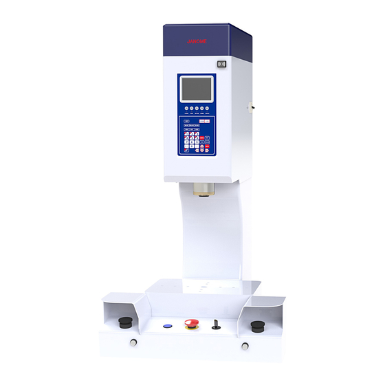
2. SYSTEM CONFIGURATION 2-1 Stand-Alone Type The illustration shows the JP-504. Front View Electro Press Area Sensor Connecting Cable (Not included in the package) Area Sensor (Not included in the packa RS-232C Cable (Not included in the package) Printer Software for Windows (Optional) Setup Electro Press JP Series 4... -
Page 15: Head Type
2-2 Head Type The illustration shows the JPH-504. Electro Press Front View 3 m Cable Switch Box Area Sensor Connection Cable (Not included in the package) Area Sensor (Not included in the package) RS-232C Cable (Not included in the package) Printer Software for Windows (Optional) Setup... -
Page 16: Unit Type
2-3 Unit Type The illustration shows the JPU-504. Unit Body Control Box Motor Power Supply Cable Encoder and Sensor Connecting Cable Load Cell Connecting Cable The teaching pendant and monitor box cannot be Monitor Box used at the same time. (Optional) Teaching Pendant 3 m Cable... -
Page 17: Installation
Attach the eyebolts provided to the top of the body to lift the Electro Press with a crane. Confirm that the eyebolts are firmly tightened. Be careful when the Electro Press is lifted because it will be inclined. JP-104/JP-204: Size of Eyebolts JP-504/JP-1004/JP-1504:... - Page 18 Unit Type Attach the 2 eyebolts to the top or rear side of the body (JPU-3004, 5004 and 8004) to lift the Electro Press with a crane. Confirm that the eyebolts are firmly tightened. JPU-104/JPU-204: Size of Eyebolts JPU-504/JPU-1004/JPU-1504: JPU-3004/JPU-5004/JPU-8004: M10 (2 pieces) Unit Type (Top view) Indicates Eyebolt Hole Unit Type (Rear)
- Page 19 After removing the eyebolt, tighten the screw provided or attach the rubber cap provided to the eye bolt fixing hole. Screw for the JP-104 and 204, JPH-104 and 204, JPU-104 to 1504 Rubber cap for the JP-504 and 1004, JPH-504 and 1004 For the unit type, tighten the screw provided to the eyebolt fixing hole indicated by the arrow.
-
Page 20: Setting
3-2 Setting 3-2-1 JP-104/JP-204, Stand-Alone Type Fix the Electro Press to the mounting base at the screw holes using 4 M10 hexagon socket bolts (JIS Strength 12.9, Length 45 mm or more) and washers. Tighten the bolts to 70 Nm tightening torque. -
Page 21: Jp-504/Jp-1004/Jp-1504, Stand-Alone Type
3-2-2 JP-504/JP-1004/JP-1504, Stand-Alone Type Fix the Electro Press to the mounting base at the screw holes using 4 M10 hexagon socket bolts (JIS Strength 12.9, Length 45 mm or more) and washers. Tighten the bolts to 70 Nm tightening torque. (Mounting Hole) Ram Center Setup... -
Page 22: Jp-3004/Jp-5004, Stand-Alone Type
3-2-3 JP-3004/JP-5004, Stand-Alone Type Fix the Electro Press to the mounting base at the screw holes using 4 M20 hexagon socket bolts (JIS Strength 12.9, Length 85 mm or more) and washers. Tighten the bolts to 390 Nm tightening torque. (Mounting Hole) Ram Center... -
Page 23: Jph-104/Jph-204, Head Type
3-2-4 JPH-104/JPH-204, Head Type Fix the Electro Press to the mounting base at the screw holes using 4 M16 hexagon socket bolts (JIS Strength 12.9, Length 65 mm or more) and washers. Tighten the bolts to 200 Nm tightening torque. Fit the switch box to the Electro Press with 4 screws (M4) using the screw holes on the rear of the unit. -
Page 24: Jph-504/Jph-1004, Head Type
3-2-5 JPH-504/JPH-1004, Head Type Fix the Electro Press to the mounting base at the screw holes using 6 M16 hexagon socket bolts (JIS Strength 12.9, Length 65 mm or more) and washers. Tighten the bolts to 200 Nm tightening torque. Fit the switch box to the Electro Press with 4 screws (M4) using the screw holes on the rear of the unit. -
Page 25: Jph-3004/Jph-5004, Head Type
3-2-6 JPH-3004/JPH-5004, Head Type Fix the Electro Press to the mounting base at the screw holes using 12 M24 hexagon socket bolts (JIS Strength 12.9, Length 85 mm or more) and washers. Tighten the bolts to 650 Nm tightening torque. Fit the switch box to the Electro Press with 4 screws (M4) using the screw holes on the rear of the unit. -
Page 26: Jpu-104/Jpu-204, Unit Type
3-2-7 JPU-104/JPU-204, Unit Type Use the keyway provided on the bottom of the Electro Press to eliminate thrust play with a pin matched to the keyway width. Fix the Electro Press to the mounting base at the screw holes using 4 M10 hexagon socket bolts (JIS Strength 12.9, Length 35 mm or more) and washers. -
Page 27: Jpu-504/Jpu-1004, Unit Type
3-2-8 JPU-504/JPU-1004, Unit Type Use the keyway provided on the bottom of the Electro Press to eliminate thrust play with a pin matched to the keyway width. Fix the Electro Press to the mounting base at the screw holes using 4 M12 hexagon socket bolts (JIS Strength 12.9, Length 45 mm or more) and washers. -
Page 28: Jpu-1504, Unit Type
3-2-9 JPU-1504, Unit Type Use the keyway provided on the bottom of the Electro Press to eliminate thrust play with a pin matched to the keyway width. Fix the Electro Press to the mounting base at the screw holes using 4 M12 hexagon socket bolts (JIS Strength 12.9, Length 45 mm or more) and washers. -
Page 29: Jpu-3004/Jpu-5004, Unit Type
3-2-10 JPU-3004/JPU-5004, Unit Type Use the keyway provided on the bottom of the Electro Press to eliminate thrust play with a pin matched to the keyway width. Fix the Electro Press to the mounting base at the screw holes using 4 M16 hexagon socket bolts (JIS Strength 12.9, Length 60 mm or more) and washers. -
Page 30: Jpu-8004, Unit Type
3-2-11 JPU-8004, Unit Type Use the keyway provided on the bottom of the Electro Press to eliminate thrust play with a pin matched to the keyway width. Fix the Electro Press to the mounting base at the screw holes using 4 M16 hexagon socket bolts (JIS Strength 12.9, Length 60 mm or more) and washers. -
Page 31: Wiring
LAN, etc. COM (RS-232C) Switch Box Load Cell Output (Optional) Analog Output I/O-S Area Sensor For CE Specifications of JP-104 - JP-1504 and Single Phase: Inlet JPH-104 - JPH-1504 only Three-Phase: Power Cable connected Setup Electro Press JP Series 4... -
Page 32: Unit Type
3-3-2 Unit Type (JPU-104 – JPU-1504) Connect the cables according to the following wiring diagram. Monitor Box Teaching Select Pendant Control Box (Front) Ethernet Output (Optional) LAN, etc. Encoder Output (Optional) Pulse Output COM (RS-232C) I/O-SYS External Device (Sequencer, etc.) I/O-1 External Device Switch Box... - Page 33 Control Box (Rear) Motor Power Cable Brake-Sensor Connection Cable Unit Body (Rear) Single Phase: Inlet Three-Phase: Power Cable connected For CE Specifications of JP-104 - JP-1504 and JPH-104 - JPH-1504 only Setup Electro Press JP Series 4...
- Page 34 (JPU-3004 – JPU-8004) Connect the cables according to the following wiring diagram. Control Box (Front) Teaching Select Pendant Monitor Box Ethernet Output (Optional) LAN, etc. Encoder Output (Optional) Pulse Output COM (RS-232C) I/O-SYS External Device (Sequencer, etc.) I/O-1 (Optional) External Device Switch Box I/O-S Area Sensor...
- Page 35 Control Box (Rear) Brake Sensor Connection Cable Encoder Connection Cable Motor Power Cable Unit Body (Side) (Rear) Single Phase: Inlet Three-Phase: Power Cable connected For CE Specifications of JP-104 - JP-1504 and JPH-104 - JPH-1504 only Setup Electro Press JP Series 4...
-
Page 36: Base Dimensions
3-4 Base Dimensions 3-4-1 JP-104/JP-204, Stand-Alone Type Use the following base dimensions when making workpiece fixtures to attach to the base plate. Setup Electro Press JP Series 4... -
Page 37: Jp-504/Jp-1004/Jp-1504, Stand-Alone Type
3-4-2 JP-504/JP-1004/JP-1504, Stand-Alone Type Use the following base dimensions when making workpiece fixtures to attach to the base plate. Setup Electro Press JP Series 4... -
Page 38: Jp-3004/Jp-5004, Stand-Alone Type
3-4-3 JP-3004/JP-5004, Stand-Alone Type Use the following base dimensions when making workpiece fixtures to attach to the base plate. Setup Electro Press JP Series 4... -
Page 39: Ram Mounting Jig
If the jig has to be mounted in some other way than using the shank mounting hole, contact Janome Sewing Machine Co., Ltd. (Industrial Automation Systems Division.) -
Page 40: Jp, Jph, Jpu-504/1004/1504
If the jig has to be mounted in some other way than using the shank mounting hole, contact Janome Sewing Machine Co., Ltd. (Industrial Automation Systems Division.) -
Page 41: Jp, Jph, Jpu-3004/5004, Jpu-8004
If the jig has to be mounted in some other way than using the shank mounting hole, contact Janome Sewing Machine Co., Ltd. (Industrial Automation Systems Division.) -
Page 42: Switching I/O-Sys And I/O-1 Power Supply
3-5-4 Switching I/O-SYS and I/O-1 Power Supply Turn OFF the Electro Press and remove the cover on the rear body (Stand-alone/Head type) or the cover on the control box (front) (Unit type) to adjust the following switches. Display Switch I/O-SYS Internal Power External Power Power Selection Switch... -
Page 43: Safeguard Installation
3-6 Safeguard Installation <How to install a safeguard> Remove the switch box and install the area sensor and safeguard. Remove the screws. Remove the rear cover. Remove the switch box fixing plate. Remove the screws. Pull the switch box out and release the cord from the cord clamp. - Page 44 ・Area Sensor ( Light Curtain ) Installation Connect to the I/O-S. Install walls for the guard. (In this case, the walls are transparent.) Light Curtain Controller In this case, the switchbox and light curtain are installed using the steel plates. The switch box cord should be inside the steel plate.
- Page 45 ・Minimum Safe Distance from Danger (In this case, the distance from the light curtain detection area) Install the light curtain with reference to the formula below. S = K x T + C S: Safety Distance (the minimum safe distance) K: Approach Speed (speed at which the hand enters) (mm/s) (calculated using “≒...
-
Page 46: How To Back Up Unique Number And Install Setting Data
4. HOW TO BACK UP UNIQUE NUMBER AND INSTALL SETTING DATA Each machine has a unique number and its own initial setting data. Be sure to back up this data since it may be necessary when replacing internal board due to malfunction. -
Page 47: How To Install Press System Software
5. HOW TO INSTALL PRESS SYSTEM SOFTWARE The Electro Press is controlled by built-in “Press system software.” To upgrade the press system software, follow the instructions below. (For this operation, the machine must be connected to a PC.) “Press system software” is included in the Operation Manual CD-ROM with the file name, JpSyp_XXX.jsy. - Page 48 Turn ON the machine again, copy the “JPJSYLDE” software included in Operation Manual CD-ROM to the local disk on the PC and start it up. Select the communication port status of your PC which is connected to the machine and then click [OK.] Select [Open] on the dialog box and specify the press system software to be downloaded.
-
Page 49: Teaching Data Backup
6. TEACHING DATA BACKUP Back up data in case of accident. To create backup data, start up the program “JP Designer Limited Edition” included in the Operation Manual CD-ROM. Retrieve data from the machine and save the retrieved data in a file. - Page 50 No part of this manual may be reproduced in any form, including photocopying, reprinting, or translation to another language, without the prior written consent of JANOME. * The “Electro Press” is a product name of JANOME. ©2004, JANOME Sewing Machine Co., Ltd., All rights reserved. 891802109 as of 08/2005...