Table of Contents
Advertisement
1.
This chapter describes the following items.
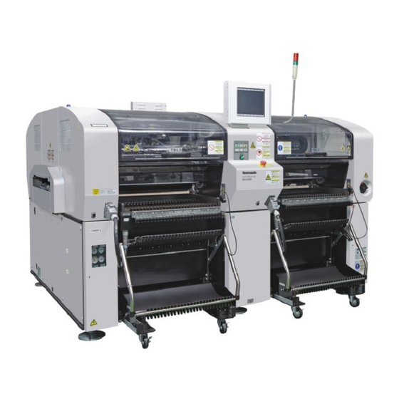
This describes the names and functions of each unit using the illustrations.
Production process
This describes the placement process step by step.
Specifications
This describes the specifications of the machine and applicable boards.
∗ This machine can use the high-speed head (12 nozzles / 8 nozzles) and the multi-functional
head.
EJM4A-E-RMA01-A00-01
1. GENERAL DESCRIPTION
CM602-L
Reference Manual
Page 1-1
Advertisement
Table of Contents

Related Manuals for Panasonic CM602-L


Summary of Contents for Panasonic CM602-L
- Page 1 CM602-L Reference Manual 1. GENERAL DESCRIPTION This chapter describes the following items. Names and mechanisms of units This describes the names and functions of each unit using the illustrations. Production process This describes the placement process step by step. Specifications This describes the specifications of the machine and applicable boards.
- Page 2 CM602-L Reference Manual 1.1 Names and Mechanisms of Units 1.1 Names and Mechanisms of Units 1.1.1 External Views 1. Front view Status indicator (Three-color signal tower) Front cover Front color touch panel Power supply switch Feeder table 3 Feeder table 1 EJM4A-AA01 2.
- Page 3 CM602-L Reference Manual 1.1 Names and Mechanisms of Units 1.1.2 Operating Units 1. Front view EJM4A-AA01 ∗ The emergency stop button, color touch panel, operating panel, and servo switch of the same number exist on the rear side. Unit name Function Qty.
- Page 4 CM602-L Reference Manual 1.1 Names and Mechanisms of Units 2. Rear view 4Z4C-AB01 EJM4A-062P Unit name Function Qty. Reference item Status indicator Indicates the machine’s operational See below. (Three-color signal tower) status, and warns you of any trouble occurred during operation by sounding a buzzer.
- Page 5 CM602-L Reference Manual 1.1 Names and Mechanisms of Units 1.1.3 Main Units EJM4A-112E Unit name Function Qty. Board conveyor L/R This unit loads and unloads boards. 1 on the In placement, it secures a board by L/R side sandwiching it in between the Y and...
- Page 6 CM602-L Reference Manual 1.1 Names and Mechanisms of Units EJM4A-144E EJM4A-143E Unit name Function Qty. XY unit These units move the head unit in place fast and precisely. Transfer head This unit transfers chips from feeders to a board. The high-speed head is equipped with 12 or 8 nozzle holders, and the multi-functional head is equipped with 3 nozzle holders.
- Page 7 CM602-L Reference Manual 1.1 Names and Mechanisms of Units 1.1.4 Component Feeding Unit EJM4A-AC01 Unit name Function Qty. Collectively changing truck This is a truck where intelligent feeders are placed. ∗ When the collectively changing truck preparation unit (option) is available, the preparation work is available while this machine is running.
- Page 8 CM602-L Reference Manual 1.1 Names and Mechanisms of Units 1.1.5 Extension Conveyor (Option) EJM4A-AG01 Unit name Function Extension conveyor This unit extends the conveyor. It can be installed on both the upstream and the downstream process side. Since its cover is equipped with a safety switch, the machine cannot be operated with that cover open.
- Page 9 CM602-L Reference Manual 1.1 Names and Mechanisms of Units 1.1.6 Recognition Camera This machine has the two recognition cameras: head camera and line camera. A) Head camera The head camera is installed on the head unit, and recognizes the precise position of board.
- Page 10 CM602-L Reference Manual 1.2 Placement Mechanism 1.2 Placement Mechanism Machine’s movable parts Rear side Front side 4Z4C-010E ∗ Description uses the photos for the high-speed head (8 nozzles). A board is loaded from the The board is clamped and 1. Loading board upstream process.
- Page 11 CM602-L Reference Manual 1.2 Placement Mechanism The board is loaded from the A The board is clamped and 3. Transporting board stage. recognized. The board on which the components have been placed at the A stage is transported to the B stage.
- Page 12 CM602-L Reference Manual 1.3 Equipment Specifications 1.3 Equipment Specifications 1.3.1 Machine Specifications Item Specifications Control system Microcomputer system ∗ 4 The data is managed by PT External memory Approximately 1 MB is required for a piece of data. (One type per 3.5-inch 2HD floppy disk) ∗...
- Page 13 CM602-L Reference Manual 1.3 Equipment Specifications 1.3.2 Basic Performance Description Item High-speed head (12 nozzles) High-speed head (8 nozzles) Multi-functional head Placement angle 0 ° to 359 ° (It can be set in increments of 0.01°.) Placement range See “1.4.1 Applicable Board Specifications.”...
- Page 14 CM602-L Reference Manual 1.3 Equipment Specifications 1.3.3 Board Flow Direction The board flow direction and the board positioning reference can be changed optionally. The reference of mount data can be set arbitrarily on PT. Standard: Left-to-right flow, Front reference Width-adjustment conveyor...
- Page 15 CM602-L Reference Manual 1.3 Equipment Specifications 1.3.4 Outside Dimensions Collectively changing truck Reference Front Board transport height (Option: 950) EJM4A-134E (All dimensions in mm) Page 1-15 EJM4A-E-RMA01-A01-00...
- Page 16 CM602-L Reference Manual 1.4 Other Specifications 1.4 Other Specifications 1.4.1 Applicable Board Specifications (1/2) Item Specifications Available board Max.: 510 mm (L) × 460 mm (W) / Min.: 50 mm (L) × 50 mm (W) dimensions 3 mm :No component area...
- Page 17 CM602-L Reference Manual 1.4 Other Specifications (2/2) Item Specifications Examples of mark shape Board recognition implements compensation through the use of the physical relationship between recognition marks and a circuit pattern. A fixed contrast is required between recognition marks and a board. (Binary-contrast image) 0.5 mm ≤...
- Page 18 CM602-L Reference Manual 1.4 Other Specifications 1.4.2 Installable Feeder Count 1. Intelligent feeder Feeder Tape Type Reel Installati Max. Feed pitch (1 pitch = 4 mm) type width diameter depth of inst. 0.5 1 2 3 4 5 6 7 8 9 10 11 12 13 14 ∗...
- Page 19 CM602-L Reference Manual 1.4 Other Specifications 2. Bulk feeder Feeder type Target chip Chip dimensions (in mm) Installation Chip aligning time (in s) Chip type pitch alignment Per chip Per feeder (in mm) count Min. in parentheses 1005C B/F 1005C 1.0 ±...
- Page 20 CM602-L Reference Manual 1.4 Other Specifications 1.4.3 Nozzle Specifications This machine is equipped with the standard nozzles in each head, supporting many different components. For high-speed head (12 nozzles): 6 types (All dimensions in mm) Target components Target components Nozzle...
- Page 21 CM602-L Reference Manual 1.4 Other Specifications Nozzle layout for high-speed head (12 nozzles) Twelve pieces of nozzles (110S, 115AS, 120S, 130S, 205S, and 206AS shown in the previous page), which support the components measuring 7.3 mm or less from one corner to the opposite corner, can be attached.
- Page 22 CM602-L Reference Manual 1.4 Other Specifications For high-speed head (8 nozzles): 9 types (All dimensions in mm) Target components Target components Nozzle (Representative 115A (Representative examples) examples) 1005R, C 1608R, C 1608, C 2012R, C SS-Mini Tr, Di S-Mini Tr, Di...
- Page 23 CM602-L Reference Manual 1.4 Other Specifications (All dimensions in mm) Target components Target components Nozzle (Representative (Representative examples) examples) SOP, QFP 0603R, C PLCC, BGA 24 mm × 24 mm Shape EJM4A-402E 4X3C-202E Target components Nozzle 206A (Representative examples) 0603R, C...
- Page 24 CM602-L Reference Manual 1.4 Other Specifications For multi-functional head: 6 types (All dimensions in mm) Target components Target components Nozzle 1001 (Representative 1002 (Representative examples) examples) 1005R, C 3216R, C 1608R, C 4532R, C 2012R, C TAN-X, B, C, D...
- Page 25 CM602-L Reference Manual 1.4 Other Specifications 1.4.4 Compatibility among Nozzles The following conditions are required for compatibility between the nozzles for the CM602 multi-functional head and those for the former models (CM301/CM20/CM120/CM100). 1. When wishing to use the nozzles for the former models on CM602, you need to attach CM401/CM402/CM602-specific orifices to them.
- Page 26 CM602-L Reference Manual 1.4 Other Specifications 2. When wishing to use the nozzles for CM401/CM402/CM602 on the former models, you need to detach CM401/CM402/CM602-specific orifices from them (for using some nozzles) or change the settings of a vacuum sensor (for using all nozzles).
- Page 27 CM602-L Reference Manual 1.4 Other Specifications Setting procedures of vacuum sensor (Example: For CM301) Make the setting on each beam. (Two indicators need to be set.) <Reference vacuum uptake value check> Attach 1003 nozzles to each head. ∗ Use the nozzles without orifices.
- Page 28 CM602-L Reference Manual 1.4 Other Specifications <Vacuum sensor setting procedure> Select the channels to be set, using keys. Change the pressure value using keys, and accept your entry by pressing • This step covers the setting of pressure value (H −...