
Related Manuals for Panasonic LP-310


Summary of Contents for Panasonic LP-310
- Page 1 表紙~はじめに Laser Marker LP-300 SERIES Operation Manual ME-LP300-OP-12 No.9000-0062-20V 2018.5 panasonic.net/id/pidsx/global...
-
Page 2: Preface
Preface Thank you for purchasing Laser Marker . For full use of this laser marker safely and properly, please read this manual carefully. This system has been strictly checked and tested prior to its delivery, however, please make sure that this system operates properly before using it. - Page 3 Please read this document carefully with respect to our product warranty policy before using our Panasonic Industrial Devices SUNX products (“Products”). If you have any questions or comments regarding do's and don'ts of the Products, please consult your local Panasonic Industrial Devices SUNX authorized dealer for the correct use and application of the Products.
- Page 4 Trademarks ■ • Window is a registered trademark or trademark of U.S.A. Microsoft Corporation in U.S.A and other countries. All other product names and companies provided in this manual are trademarks or registered trademarks of their respective companies. Warranty of Product ■...
- Page 5 MEMO...
-
Page 6: Cautions In Handling Laser Beam
Cautions in Handling Laser Beam This product falls into Class 4 laser (marking laser) and Class 2 laser (guide laser) based on the classifications of IEC60825- 1 “Safety of laser products”. Class 4 laser refers to “Laser products for which intrabeam viewing and skin exposure is hazardous and for which the viewing of diffuse reflections may be hazardous. - Page 7 DANGER Never look at laser beam directly or through lens. Diffused reflected beam is also harmful. laser does not enter into eye's retina, however, if it exposed to the eyes, it can inflict severe corneal injuries. Never touch laser beam. Be careful not to touch laser beam with clothing as well.
-
Page 8: Safety Protection Measures
Safety Protection Measures This product falls into Class 4 laser (marking laser) and Class 2 laser (guide laser) based on the classifications of the Safety of laser products (JIS C 6802) / FDA standards 21 CFR 1040.10 and 1040.11/IEC60825-1. Perform the safety protection measure shown below before using the system. For more detail instruction, refer to each of the standard. - Page 9 5. Power failure recovery For power failure occurs on the laser marker, construct a laser re-pumping system by manual operation for safety. 6. Radiation direction of laser beam To assure safety, be sure to place the protective enclosure. Measures should be taken so that the direction of laser radiation can be seen and checked by others as well as an operator.
-
Page 10: Functions For Safety Measures
Functions for Safety Measures This laser marker has the functions shown below for safety measures. Head Section ■ 1. Shutter Lever • The laser can be radiated with the shutter opened, or it cannot be radiated with the shutter closed. Howevr, the guide laser is available. - Page 11 Head rear side Certification and identification label *1 Warning, explanatory, aperture label • LP-310 Warning, explanatory, aperture label Protection Housing Label • LP-310-A • LP-310-C Warning, explanatory, aperture label Protection Housing Label Certification and identification label *1 *1: Attached to LP-310-A only.
- Page 12 Power Supply BOX ■ 1. Power Supply Display • When turning ON the key switch, this indicator flashes in green. When the system starts up and runs completely, the indicator switches into lighting status. 2. Key Switch • This key switch is used to start the laser marker system. While the switch is ON, the key cannot be removed, however, while it is OFF, the key can be removed.
- Page 13 I/O Connector ■ • This product is equipped with the laser radiation stop input in the I/O connector. Pin 4 Laser Radiation Stop Input Lase r Marker Side Co nne ctor Type : F emale D-sub 2 5 pin User Side Co nnector Ty pe : Male D -su b 25 pin * * As a user side connector, following items are attached to this product.
- Page 14 Construction Sample of Interlock System ■ • For operating this product, construct the protective enclosure enclosing the range of the laser radiation for protecting the exposure caused by the reflection of the laser radiation from the object being marked or the surrounding objects, and also construct the interlock system at the same time.
-
Page 15: Cautions In Handling
Cautions in Handling Handling the System ■ WARNING This product has been developed/produced for industrial use only. When using the system, do not touch laser beam with any part of body, papers, or clothing, etc. This product contains ZnSe (zinc selenide) in the lens mounted on the laser radiation window. - Page 16 CAUTION Use this product neither in inflammable gas, a dusty place nor the place of fire strict prohibition. It might cause a fire. Gasoline Never put the object which is easy to burn on near. It might causes a fire. Construct an interlock systems such as a function to stop laser radiation for the maintenance door of the protective...
- Page 17 CAUTION Be sure to connect the head to the exclusive controller. It will cause a failure if it connects with any equipment other than the exclusive controller. Moreover, it may be exposed to dangerous laser radiation. When re-switching on the power supply, after turning OFF key switch of the power supply BOX supply and 5 seconds or more pass, turn ON key switch of the power supply BOX again.
- Page 18 지역에서 사용하는 것을 목적으로 합니다 . *1:Contact for CE: Panasonic Marketing Europe GmbH, Panasonic Testing Center Winsbergring 15, 22525 Hamburg, Germany *2:Although EN 60204-1 is applied as a harmonized standard of LVD, EN 61010-1 is partially applied to enhance the conformity with electrical safety and requirement of LVD.
- Page 19 Equipment Harnessed High Frequency Wave ■ Our CO laser marker harnesses high frequency wave internally. Because the product has the mechanism generating laser, it is classified into “various equipment” in the equipment harnessed high frequency wave in Japan. Before using the product, please check whether the product is required to apply the similar law and regulation described above or not in user’s region/country, and if required, go through the required procedure(s) by the user.
- Page 20 Detaching Method of Battery ◆ The method for detaching the used battery installed in the laser marker to be disposed is described below in accordance with the EU Battery Directive (2006/66/EC). • When detaching the used battery, be sure to disconnect the power cable so that the power shall not be supplied to the device.
- Page 21 MEMO...
-
Page 22: Table Of Contents
Contents Preface.........................2 Cautions in Handling Laser Beam................6 Safety Protection Measures ..................8 Functions for Safety Measures ..................10 Cautions in Handling ....................15 Contents ........................22 Construction of Manual ....................27 1 Preparation ....................31 1-1 Package Check....................32 1-2 Name of Each Part....................34 1-2-1 Head......................34 1-2-2 Power Supply BOX...................35 1-3 Installation......................36 1-3-1 Installation Method ...................36... - Page 23 3-1-4 Tool Button Function ................81 3-2 File Selection ....................... 82 3-2-1 Marking File....................82 3-2-2 Registration File ..................83 3-2-3 Registration File and Marking File............86 3-3 Character Setting....................88 3-3-1 Character Setting Screen................. 88 3-3-2 Input of Marking Character............... 89 3-3-3 Input of Function Character..............
- Page 24 3-11-1 Remote Mode..................144 3-11-2 PC Control Mode.................146 3-12 Switching Language between Japanese and English........147 3-13 Error History .....................148 3-14 Environmental Setting..................150 3-14-1 Environmental Setting Related to Laser Marker........150 3-14-2 Environmental Setting Related to PC...........152 4 External Control..................155 4-1 Control Through I/O Connector................156 4-1-1 Before External Controlling Laser Marker Using I/O Connector.....156 4-1-2 I/O Connector ..................157 4-1-3 Signal Name and Content of I/O Connector...........159...
- Page 25 7-2-2 Power Supply BOX ................196 Appendix ...................... 197 Character Code Table....................198 Readable DXF File....................207 Glossary........................209 Index ......................212 Index ........................213...
- Page 26 MEMO...
-
Page 27: Construction Of Manual
Construction of Manual The important items for safety laser marker operation are described in Before Use this section. Be sure to read this section before using the laser marker. Chapter This chapter describes the items Preparation required for using the laser marker. P.31 Be sure to read this chapter at preparation. - Page 28 “Let’s Try” Contents The user can refer to the corresponding pages in which the contents of what user “tries to do” are described using this “Let’s Try” Contents. Setup Laser Marker Install Setting Software Install and Connect “Installation” P.36 Installation Install “Connecting Laser Marker”...
- Page 29 Marking Mark Logo Set Character Condition Character Interval Angle Character Width Character Height Line Interval Start Radius Start Angle Radius Center Position (X, Y) “CAD Condition” P.120 “Character Condition” P.115 Control Laser Marker From External Device Control by RS-232C Control by I/O Personal Computer “Control Through I/O Connector”...
- Page 30 MEMO...
-
Page 31: Preparation
1 Preparation 1-1 Package Check ..................32 1-2 Name of Each Part ..................34 1-3 Installation ....................36 1-4 Connecting Laser Marker ................40 1-5 Connecting with External Device.............42... -
Page 32: Package Check
CD-ROM Warning, explana- Interlock Connector tory, aperture label Controller • LP-310/LP-310-A : Rated 125V, 3m • LP-310-C : Rated 250V, 3m The following data is stored in CD-ROM. • LP-310 PC Setting Software • PDF data of LP-300 series Operation Manual (Japanese / English / Chinese) - Page 33 MEMO...
-
Page 34: Name Of Each Part
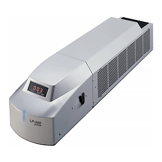
Name of Each Part 1-2-1 Head 1. Laser Radiation Indicator This indicator indicates the laser radiation state. (Refer to “Functions for Safety Measures” (P.10) for details.) • Lights up in blue: Indicates while the power supply is ON. • Lights up in red: Indicates the marking laser is radiated. Also this indicator flashes for 0.5 seconds just after turning on the power supply. -
Page 35: Power Supply Box
90V to 132V AC or 180V to 264V AC (including +/-10% voltage fluctuations), 50/60Hz (Voltage and frequency are switched automatically.) The voltage of the attached AC power cable is 125V rating for LP-310/310-A, 250V rating for LP-310-C. Be sure to connect the ground pin of the AC power cable to earth permanently. -
Page 36: Installation
Installation 1-3-1 Installation Method (1) Installation Method Head This head can be fixed from the bottom with M6 screw at six locations. • The inserting length of the screw shall be 10mm or less. • The tightening torque shall be 2.0N•m or CHECK less. - Page 37 (2) Installation Direction For making use of the laser marker safely and fully, install the laser marker in either direction shown below: Head Do not incorporate the laser marker in a unit where the laser head will be moved. It may cause failure.
-
Page 38: Center Of Marking
(3) Installation Space Since this product is operated by the forced air-cooling, both fan and slit for cooling are equipped. Make space around the product as shown in the following figure. Head Power Supply BOX Min. 15cm 15cm以上 Min. 15cm 15cm以上... -
Page 39: Useful Function For Installation
1-3-3 Useful Function for Installation Guide Laser Function ■ The marking contents and marking area can be traced with the red guide laser. By using the guide laser function, the position adjustment of the marking is available easily. Refer to “3-8 Guide Indication” (P.134) for details of the operating method. -
Page 40: Connecting Laser Marker
Connecting Laser Marker 1-4-1 Connecting Head and Power Supply BOX Connect the following items using the attached specific cables. Head Wiring of I/O Power Supply BOX To Interlock Connector To Inlet Head Power Cable (5m) To POWER AC Power Cable (5m) To Interlock System •... -
Page 41: Connecting Laser Marker And Personal Computer
1-4-2 Connecting Laser Marker and Personal Computer Connect the following items using the attached specific cables. Head Personal Computer USB Cable The function that several LP-310s are operated with only one personal computer is not incorporated. REFERENCE... -
Page 42: Connecting With External Device
Connecting with External Device 1-5-1 Operation Sample Using External Control Device In case of controlling the laser marker with the external control device, the following two connecting methods are applicable. 1. External Control Using I/O Connector (Remote mode) Head Power Supply BOX 2. -
Page 43: Operation Procedure Using External Control
1-5-2 Operation Procedure Using External Control This section describes the basic operation procedures using the external control. Flow Chart ■ * The procedure marked with is performed by manual. OPEN manual shutter of laser marker head. 1. External control using I/O connector 2. -
Page 44: Shift To Remote Mode
1-5-3 Shift to Remote Mode In case of controlling the terminal block using the external device such as I/O connector and RS-232C, it needs to shift the laser marker to “Remote Mode”. Before performing the external control by either method show below, shift the laser marker to remote mode. -
Page 45: Basic Operation Procedure
2 Basic Operation Procedure 2-1 When Using Laser Marker for the First Time ..........46 2-2 Setting Procedure for Basic Function............58... -
Page 46: When Using Laser Marker For The First Time
When Using Laser Marker for the First Time The procedure for using the laser marker for the first time after purchasing from performing test marking the character (sample show below) until turning off the power supply is described below. Sample ■... -
Page 47: Preparation Of Laser Marker Operation
2-1-1 Preparation of Laser Marker Operation Check the package. Check the package referring to “1-1 Package Check” (P.32). If something is lack, as for the nearest sales office. Install the laser marker. Install the laser marker referring to “1-3 Installation” (P.36). Install “LP-300 series PC Setting Software”... -
Page 48: Startup Of Laser Marker
2-1-2 Startup of Laser Marker Turn ON the key switch of the power supply BOX. (Insert the key and turn it toward ON side.) The laser radiation indicator lights up in red for approx. 0.5 seconds, and then it changes the lit color into blue. -
Page 49: Procedure From Laser Marker Setting To Test Marking
2-1-3 Procedure from Laser Marker Setting to Test Marking 1. Set the file No. to be marked. The “File Selection” screen is displayed when starting the PC setting software. Select the File No. “003” on the file selection screen. Pressing File No. 003 highlights the comments column, and “003”... - Page 50 The screen is changed into “Inputting Of Characters”. Here inputs “ABCD”. (Input the character using the keyboard of the PC.) *In case of operating under Japanese OS, input the double-byte character. Press Here inputs “ABCD”. (Input the character using the keyboard of the PC.) The character “ABCD”...
- Page 51 Press CHARACTER Press the setting value of the [Character Height]. Input “4”. (Input the value using the keyboard of the PC.) Press the setting value of the [Character Width]. Input “4”. (Input the value using the keyboard of the PC.) Press the setting value of the [X Position].
- Page 52 Press the setting value of the [Y Position]. Input “5”. (Input the value using the keyboard of the PC.) Press the setting value of the [Character Interval]. Input “5”. (Input the value using the keyboard of the PC.) Press [Image], and check the image screen.
- Page 53 4. Set the laser. Here describes the procedure for setting laser power at 30 and scan speed at 300mm/s. Press Press setting value of the [Laser Power]. Input “30”. (Input the value using the keyboard of the PC.) Press setting value of the [Scan Speed]. Input “300”.
- Page 54 5. Perform test marking from PC in PC control mode. Set the work to be marked and adjust the distance between the laser marker and the work. Set the distance from the lower surface of the scanning unit of the head to the surface of the work to be marked at 145mm.
- Page 55 When selecting “Yes”, the file is transferred to the laser marker, and the guide indication with red laser is started. Adjust the marking position by moving the work to be marked or other method. When clicking the “STOP” button, the dialog box shown in the right figure is displayed.
- Page 56 When selecting “Yes” on [Start of printing] dialog box, the file is transferred to the laser marker, and the marking is started. If the file No. under editing on PC is also existed on the head, the overwriting confirmation dialog box shown in the right figure is displayed.
-
Page 57: Turn Off Power Of Laser Marker
6. Save the setting contents. Here describes the procedure for saving the setting file conditions to PC. When selecting “File” - “Save As”, the dialog for setting file name is appeared. Set the file name and saving place, and press “Save”. -
Page 58: Setting Procedure For Basic Function
Setting Procedure for Basic Function The setting method for function to be applied to the actual marking is described in this section using sample. 2-2-1 Mark Counter Sample ■ 0001 0002 0003 ••••••• 0998 0999 1000 0001 0002 Set the counter shown above. Flow Chart ■... - Page 59 a. Set the counter. Refer to “3-4-3 Setting of Counter Function” (P.106) for detail setting. Press , and press “COUNTER”. Set “1” to [Init (Initial value)]. Input the numeric using the keyboard of the PC. Set “1000” to [End (End value)]. Input the numeric using the keyboard of the PC.
- Page 60 b. Input the counter function character. Refer to “3-3-3 Input of Function Character” (P.90) for details. Press Adjust the cursor to the first line (01), and press EDIT * Re-adjusting the cursor to the first line (01) and then pressing (double-clicking) the same cursor performs the same operation.
- Page 61 Check [Zero indication]. Press , and then press FUNC. INPUT The “\%04:C0” is input in the 01 line of the marking charac- ter. Press and check the image. The “0000” is displayed. The counter becomes “0000” because the current value of the counter is not impossible to be speci- fied in remote mode.
-
Page 62: Mark Lot No
2-2-2 Mark Lot No. Sample ■ January February March April December ••••••• Set the lot No. above. Flow Chart ■ 1. Set the lot. The detail is described in “ a. Set the lot.” (P.63). 2. Input the function character of the counter. The detail is described in “... - Page 63 a. Set the lot. Refer to “3-4-4 Setting of Lot Function” (P.107) for detail setting. Press , and press “LOT”. Set “1” to [Lot func.] The lot function is available for setting up to 4 (1 to 4) per file. REFERENCE Set “Curr date”...
- Page 64 Set both [Period] and [Marking Characters]. *In case of operating under Japanese OS, input the double- byte character. (Set both period and marking character using the key board of PC as follows:) Marking Character String Period 1 to 1 2 to 2 •...
- Page 65 Press [LOT]. Set “1” to [Lot No.]. Set the lot function No. using button. Press , and then press FUNC. INPUT The “\%SFT:1” is input in the “01” line of the marking string. Press and check the image. The image of the target marking character is displayed.
-
Page 66: Mark Expiry Date
2-2-3 Mark Expiry Date Sample ■ Expiry Date 1102 Month Here the expiry date 30 days after the current date is marked. Flow Chart ■ 1. Set the expiry date. The detail is described in “ a. Set the expiry date.” (P.67). 2. - Page 67 a. Set the expiry date. Refer to “3-4-2 Setting of Expiry Date Function” (P.105) for detail setting. Press , and press “EXPIRY”. Here the condition is set to the Expiry 1. The expiry is available for setting up to 4 (1 to 4) per file. REFERENCE Input “30”...
- Page 68 b. Input the expiry date function character. Refer to “3-4-2 Setting of Expiry Date Function” (P.105) for detail setting. Press Adjust the cursor to the first line “01” on the screen, and press EDIT * Re-adjusting the cursor to the first line (01) and then pressing (double-clicking) the same cursor performs the same operation.
- Page 69 Check “Month”. Check “ Month” for setting. The unit is set to “Month” with “ Month”. Check [Zero indication]. Check “ Zero indication” for setting. The display state is set with “ Zero indication”. Press FUNC. INPUT Continuously, check “Day”. Check “...
- Page 70 Check [Zero indication]. Check “ Zero indication” for setting. The display state is set with “ Zero indication”. Press , and then press FUNC. INPUT The “\%02:M1\%02:D1” is input in the 01 line of the marking string. Press and check the image. The image of the target marking character is displayed.
-
Page 71: Mark Current Date
2-2-4 Mark Current Date Sample ■ 12 : 30 Hour Minute This section describes the procedure for setting the current time. Flow of Procedure ■ 1. Input the function character of the date. The detail is described in “ a. Input date function character.” (P.72) 2. - Page 72 a. Input date function character. Refer to “3-4-2 Setting of Expiry Date Function” (P.105) for detail setting. Press Adjust the cursor to the first line “01” of the screen, and press EDIT * Re-adjusting the cursor to the first line (01) and then pressing (double-clicking) the same cursor performs the same operation.
- Page 73 Check [Zero indication]. Check “ Zero indication” for setting. The display state is set with “ Zero indication ” Press FUNC. INPUT Continuously, set “2” to [Figure]. Set the display digit using button. The display digit can be set among 1 to 6. REFERENCE Check [Minute].
- Page 74 Press , and then press FUNC. INPUT The “\%02:H0\%02:m0” is input in the 01 line of the marking string. Press and check the image. The image of the target marking character is displayed. The current time (Hour/Minute) is set.
-
Page 75: Description Of Operation Screen
3 Description of Operation Screen 3-1 Description of Main Screen ..............76 3-2 File Selection...................82 3-3 Character Setting ..................88 3-4 Function Setting ..................104 3-5 Marking Condition .................110 3-6 Laser Setting ..................126 3-7 Image Display..................130 3-8 Guide Indication ..................134 3-9 Test Marking..................138 3-10 Send/Read ..................140 3-11 PC Control/Remote Mode ..............144 3-12 Switching Language between Japanese and English ......147... -
Page 76: Description Of Main Screen
Button Main Screen * The “Language” is displayed when the LP-310 setting software is installed into the PC installed Windows Japa- nese OS. (When the LP-310 setting software is installed into the PC installed Windows English OS, the “Language” is... - Page 77 • Marking File P.82 • New Creation P.83 • Open P.84 File Selection • Save P.85 (P.82) • Save As P.85 • Registration File and Marking File P.86 • Character Setting Screen P.88 Character Setting • Input of Marking Character P.89 •...
-
Page 78: Construction Of Main Screen
3-1-2 Construction of Main Screen 1 Title Bar : Displays the application name, registration name, and file No. of marking file. 2 Menu Bar : Displays basic menu. “3-1-3 Menu Function” (P.79) for details. Refer to 3 Tool Bar : The edit functions of the file are minimized. Refer to “3-1-4 Tool Button Function”... -
Page 79: Menu Function
3-1-3 Menu Function File ■ Item Description Creates a new registration file. New File Clicking button performs the same function. (P.83) Reads the existing registration file. Open Clicking button performs the same function. (P.84) Saves the registration file under editing. Save Clicking button performs the same function. - Page 80 Mode ■ Item Description Switches mode between “Remote Mode” and “PC Control Mode”. PC Control/Remote Clicking performs the same function. (P.144) Window ■ Item Description Cascade Displays the opening windows in cascade status. Tile Displays the opening windows in tile status. Arrange Arranges the shifted icons at lower side.
-
Page 81: Tool Button Function
This software can select the display language from either “Japanese” or “English” by pulling down this button. * The “Language” is displayed when the LP-310 setting software is installed into the PC installed Windows Japanese OS. (When the LP-310 setting software is installed into the PC installed Windows English... -
Page 82: File Selection
File Selection 3-2-1 Marking File This function selects the marking file to be edited/set. 1 View - “File” 2 Click The “File Selection” screen for selecting marking file is appeared by clicking either selecting “1” method or clicking “2” button described above. Item Description 1. -
Page 83: Registration File
A new registration file can be created by either selecting “1” or clicking “2” icon described above. If the existing file is under editing without saved, the check dialog box “LP-310 Setting Software” whether the current file requires saving or not is appeared. - Page 84 Open ■ With this operation, the existing registration file is read. 1 “File” - “Open” 2 Click The dialog box for opening the registration file is appeared by either selecting “1” method or clicking “2” icon described above. File name Sets the file name of the registration file to be read.
- Page 85 Save ■ With this operation, the registration under editing is saved (overwritten). 1 “File” - “Save” 2 Click icon. The registration file under editing is saved (overwritten) by either selecting “1” method or clicking “2” icon described above. When saving a new created registration file (with its name not registered) after editing, the dialog box for setting file name is appeared.
-
Page 86: Registration File And Marking File
3-2-3 Registration File and Marking File Registration file Parent file to be saved in PC. This file can set 120 sub files (marking files) into it (extension: “.LLM”) Marking file Independent sub file to be used for marking. Create one registration file for each laser marker. Sample of registration file name: “Product Line A.LLM”... - Page 87 MEMO...
-
Page 88: Character Setting
Character Setting 3-3-1 Character Setting Screen The character to be marked is set by inputting from “Character Setting” screen. 1 “View” - “Character” 2 Click The “Character Setting” dialog box is appeared by either selecting “1” method or clicking “2” button described above. -
Page 89: Input Of Marking Character
3-3-2 Input of Marking Character Setting Flow ■ Click “Character Setting” button Select line to be set, Double-click line to be edited. and click button. EDIT “Inputting Of Characters” dialog box is appeared. Input the string to be marked using the keyboard. The input character is appeared in the marking string field. -
Page 90: Input Of Function Character
3-3-3 Input of Function Character The “Inputting Of Character” screen can also be input the function character other than normal character. (1) Input current date Outline Function for marking date and time of the internal clock in the main body of the laser marker. 1 Figure Sets the figure with button. - Page 91 Setting Flow ■ Click “CURRENT” tab. The “Current date input” dialog box is appeared. Select “Figure”, “Display Content”, and “Zero indication”. Click FUNC. INPUT The 7-digit character string beginning with “\” in single-byte character is displayed in the marking character string field. Cancel Click , save the...
- Page 92 (Display Sample) % 0 1 : Y 0 Display Description Indicates the functionnal character string. Sets zero indication. Set the R.justified. (single-byte space) The display digit from 1 to 6 is displayed in the “*”. Sets the dominical year. Sets the era year. Sets the month.
- Page 93 (2) Input expiry date Outline Function for marking expiry date adding the value input at function setting to the date and time of the internal clock in the main body of the laser marker. 1 Expiry No. Sets the expiry No. with button.
- Page 94 Setting Flow ■ Click “EXPIRY” tab. The “Expiry date input” dialog box is appeared. Select “Expiry No.”, “Figure”, “Display Content”, and “Zero indication”. FUNC. INPUT Click The 7-digit character string beginning with “\” in single-byte is displayed in the marking character string field. Cancel Click , save the...
- Page 95 (Display Sample) % 0 1 : Y 1 Display Description Indicates the functional character string. Sets zero indication. Set the R.justified. (single-byte space) The display digit from 1 to 6 is displayed in the “*”. Sets the dominical year. Sets the era year. Sets the month.
- Page 96 (3) Input counter Outline Function for increasing the value every marking 1 Figure Sets the figure with button. The setting range is selectable among 1 to 8. 2 Zero indication Either item can be selected by checking the corresponding radio button. Radio Button Description Zero indication...
- Page 97 (Display Sample) % 0 4 : C 0 Display Description Indicates the functional character string. Sets zero indication. Set the R.justified. (single-byte space) The display digit from 1 to 8 is displayed in the “*”. Indicates the function character of the counter. Sets the counter with zero fixed.
- Page 98 (4) Input lot Outline Function for marking duration and character string input at function setting in accordance with the internal clock in the main body of the laser marker. 1 Lot No. Sets the lot No. with button. The setting range is selectable among 1 to 4. Setting Flow ■...
- Page 99 (Display Sample) % S F T : 1 Display Description Indicates the functional character string. Indicates the function character for lot. “*” is varied in accordance with the lot function No. (1 to 4). The lot function is referred to the marking function that marks the character string set with a certain duration.
- Page 100 (5) Input optional character string Outline Function for marking the optional character string in the ASCII code using the communications from the external device such as PLC. 1 Char No. Sets the character No. with button. The setting range is selectable among 1 to 4. 2 Figure Sets the figure with button.
- Page 101 Setting Flow ■ Click “FREE” tab. The “Input of optional character string” dialog box is appeared. Select “Char. No.” and “Figure”. FUNC. INPUT Click The 7-digit character string beginning with “\” in single-byte is dis- played in the marking character string field. Cancel Click , save the...
- Page 102 (6) Input registration character Outline Function for using the registration character registered in the user font. (In case the registration character is not registered in the user font, nothing is displayed in the list. In case of using the registration character, it needs to register the character beforehand.) Setting Flow ■...
- Page 103 (Display Sample) Display Description Indicates the registration character. Indicates the registration character No. (0 to 9, A to Z, a to z) in the “*”. • The registration character function is the function for using the registration character registered in the user font. Refer to “Character Code Table” (P.198) for detail content of the registration character at initial condition.
-
Page 104: Function Setting
Function Setting Here describes the function condition of the character string to be marked. 3-4-1 Function Setting Screen The marking character is set and input on the “Function Setting” screen. 1 “View - “Set Func” 2 Click The “Function Setting” dialog box is appeared by either selecting “1” method or clicking “2” button described above. -
Page 105: Setting Of Expiry Date Function
3-4-2 Setting of Expiry Date Function The expiry date function is the function for adding the days to the expiry date to the current date/time set in the environmental setting. Item Description 1. Expiry No. Four expiry Nos. from 1 to 4 are available to be set. 2. -
Page 106: Setting Of Counter Function
3-4-3 Setting of Counter Function The counter function is the function for increasing the value from the initial to the end value stepwise. Item Description 1. Curr Value of the current counter (Current value) Setting range: 0 to 99999999 Initial value and end value of the counter. When determining each value, the counting is performed as follows. -
Page 107: Setting Of Lot Function
3-4-4 Setting of Lot Function The lot function is the function for marking the character string set for each period in accordance with the internal clock in the laser marker. Item Description 1. Lot Func. (Log Function) Four types from 1 to 4 can be set. 2. - Page 108 <Setting Method and Sample of Period> The sample of the period setting method is shown as follows. 1. In case of selecting year, month, day, hour, or week for the period condition: <Sample with the period condition “M (month)”> Input the period into the input field within the setting range of each period condition in single-byte character. Input the character string to be marked into the input field of “Marking Characters”...
- Page 109 3. In case of selecting Day of Week for the period condition: <Sample with the period condition “Day of Week”> Click the input field of the period. The list box is displayed and a day of the week can be selected from it. Input the character string to be marked into the input field of the marking character string within 10 letters.
-
Page 110: Marking Condition
Marking Condition 3-5-1 Setting Screen of Marking Condition Here describes the conditions for marking character string and CAD file. 1 “View” - “Condition” 2 Click The “Marking Condition” dialog box is appeared by clicking either selecting “1” method or clicking “2” button described above. -
Page 111: General Conditions
3-5-2 General Conditions On the GENERAL screen, set the offset of the marking position and inversion of the marking for all character strings including in the file or CAD file. Item Description Setting range 1. Mirror Marks the character string or CAD file at a position symmetric to Check box (Y axis symmetry) the Y axis. - Page 112 (1) Mirror inversion The mirror inversion has two types, horizontal inversion (Mirror) and vertical inversion (Flip). • “Mirror” Horizontal mirror inversion (Y axis symmetric) All character strings and CAD files are marked at the position symmetric to Y axis. • “Flip”...
- Page 113 (2) Offset The offset has three types, X offset, Y offset, and Rotation offset. • X/Y offset X offset moves the origin in X direction, and Y offset moves the origin in Y direction. Setting range: -25.00 to +25.00mm Step : 0.01mm •...
- Page 114 Both the mirror inversion and the offset can be set simultaneously. REFERENCE General conditions are set for correcting misalignment to the line axis caused when the laser marker is installed. Set this function to check the actual marking results and apply fine adjustment. If overall conditions are set before other conditions are set, it becomes difficult to set the character CHECK conditions and CAD conditions.
-
Page 115: Character Condition
3-5-3 Character Condition On the character setting screen, set the shape of marking, size and position of character for the marking char- acter string in the respective lines of the character setting. Item Description Setting Range Enables to set the character condition for each condition No. 1. - Page 116 (1) Marking shape and character setting The character setting items are varied depending on the selected marking shape. Here describes the character conditions to be set for each marking shape. 1. Straight Line Y Axis Y軸 Character Marking Starting Width 文字幅...
- Page 117 2. Tilt Character Internval Character Width Tilt Angle Character Height Line Interval Marking Start Position Item Description Setting Range 0.20 to 50.00mm 1. Character Height Sets the character height. (Step: 0.01mm) 0.20 to 50.00mm 2. Character Width Sets the character width. (Step: 0.01mm) Moves the marking start position of the character string in +/-25.00mm...
- Page 118 3. Fan Like Form (Clockwise circle outside, counterclockwise circle inside) Character Character Interval Angle Interval Angle Character Character W idth W idth Character Character Character Height Height Line Interval Line Interval Start Start Start Radius Radius Start Angle Radius Radius Angle Center Position (X, Y) Center Position (X, Y)
- Page 119 (2) Bold Set the bold width of the character stroke. Setting range: 0.00 to 6.00mm (Note that this item max. available bold width of the character stroke must be one-fourth of whichever smaller one of character height and character width. In case of inputting larger value than this limit, the error message “Specify bold character line width in the range of 0.00 to ** [mm].”...
-
Page 120: Cad Condition
3-5-4 CAD Condition On the CAD condition screen, the conditions for setting the marking of the data created by AutoCAD and so on (DXF file) are set. Item Description Setting Range 1. CAD No. Selects the registration No. of the CAD data to be marked 1 to 15 using the list box. - Page 121 (1) CAD file This item displays the list of the registered CAD file by clicking the list box. Click the file to be marked (DXF file) and specify the file. Note that when selecting “None (no CAD setting)”, no CAD file is set. Refer to “Character Code Table”...
- Page 122 (2) Font When the character is used for each CAD file, select the font for displaying a character by the setting software and marking by the laser marker from the registered font file. A user font is used for the font file other than alphanumeric characters. CHECK Refer to “3-14-2 Environmental Setting Related to PC”...
- Page 123 Some graphics cannot be marked as displayed in the image display if a DXF file created by AutoCAD is read in by the setting software. Refer to “Readable DXF File” (P.207) for details of the correspondence table between the LP-310 CHECK setting software and the drawing function of AutoCad.
-
Page 124: Laser Check
3-5-5 Laser Check The laser beam for the laser check is continuously emitted to a desired spot in the marking area. Item Description Setting Range 1. Laser check input Specifies the laser check. Check box 2. X/Y Position Specifies the position of the laser check. +/-25.00mm (Step: 0.01mm) 3. - Page 125 MEMO...
-
Page 126: Laser Setting
Laser Setting 3-6-1 Screen for Laser Setting The condition of the marking laser for marking a character string or CAD file is set on this screen. 1 “View” - “Set Laser” 2 Click The “Laser Setting” dialog box is appeared by clicking either selecting “1” method or clicking “2” button described above. -
Page 127: Line Width
3-6-2 Line Width Line Line Line Width Width Width Too large line width Proper Too small line width The line width is the setting value for creating the clearance at the intersection of the character strokes. The initial value of the line width is set so that the character strokes are not overlapped at the intersection in the case of general marking. -
Page 128: Adjustment Of Laser Start/End Points
3-6-4 Adjustment of Laser Start/End Points Light (shallow) Dark (deep) Proper The depth, shape, visibility, etc. of the marking are changed depending on the type of the target object, scan speed, laser power, etc. By using this function, the depth at the start/end points can be reduced and the marking shape can be adjusted. -
Page 129: Adjustment Of Marking Quality
3-6-5 Adjustment of Marking Quality This product marks the curved portion by diving them into straight lines. The roughness of the division can be set in eleven steps. When a small character is marked, the character looks a curve even if this parameter is set relatively rough. -
Page 130: Image Display
Image Display 3-7-1 Image Display Screen This screen displays the marking image of the data that has been set. 1 “View” - “Image” 2 Click The “Image Display” dialog box is appeared by clicking either selecting “1” method or clicking “2” button described above. -
Page 131: Magnification Method
3-7-2 Magnification Method (1) Zoom-in/out buttons and magnification list box Open the list box and select the magnification. Zoom-in Button Zoom-out • Zoom-in/out buttons: Zooms in and out the image by clicking the corresponding button. • Magnification list box: Selects a desired magnification for display from the list box. The reference position of the zoom-in/out is set on the center of the image display screen. -
Page 132: Adjustment Of Marking Position
3-7-3 Adjustment of Marking Position When clicking button, the mouse cursor is changed. With pressing the left button on the desired character string for moving, move the mouse to the desired position and release the button. (The color of the selected character string is changed into red.) •... -
Page 133: Adjustment Of Display Position
3-7-4 Adjustment of Display Position When clicking button, the mouse cursor is changed. With this state, press and hold the left mouse button on the image display and drag the image with the mouse to the desired position for display and release the mouse. The display position of the image is moved. -
Page 134: Guide Indication
Guide Indication The indication of the center position and actual marking character string can be traced (guide indication) on the actual work using the red laser. The operation of the guide indication is performed in PC control mode. • When activating the guide indication, perform the guide indication with the shutter (guide indication switching lever) closed. - Page 135 (1) Series The guide indication is continuously performed with the laser marker. When the file No. under editing on the PC is also existed in the head, the following dialog box for checking whether the file is allowed overwriting or not is displayed (if there exists no file with the same file No. in the head, this dialog box is not displayed).
-
Page 136: Cautions
(2) Once Perform the guide indication with the laser marker at one time. When the file No. under editing on the PC is also existed in the head, the following dialog box for checking whether the file is allowed overwriting or not is displayed (if there exists no file with the same file No. in the head, this dialog box is not displayed). - Page 137 MEMO...
-
Page 138: Test Marking
Do not perform any key operation (Enter, Space, etc.) in this state. Display the dialog box in the front of the PC screen by clicking the software name (LP-310 setting software) displayed on the Windows task bar or via keyboard operations (“Alt” + “F6”, “Alt” + “Tab”), and CHECK click “Yes”... - Page 139 It is impossible to perform the test marking for an empty file (including no setting). Click “OK” button, re-select the file, and select the operation from either “1” or “2”. • In PC control mode, the RS-232C command and input from the external I/O connector become invalid.
-
Page 140: Send/Read
3-10 Send/Read This section describes the relative processing to the transfer and reading of the file. 1 “File” - “SEND/READ” 2 Click The following screen is appeared by clicking either “1” or “2”. (The following screen is the sample by clicking the operation “2”.) From the “Send/Read”... - Page 141 If the file with the same file No. that is to be transferred is already existed in the head, the following dialog is appeared. Item Description 1. Yes Overwrite the file 2. No Not overwrite the file 3. No to All Not overwrite all files 4.
-
Page 142: File List
3-10-2 File List The list of the marking files that have already been transferred to the head (laser marker body) can be confirmed. 3-10-3 Backup The marking files that have already been transferred to the laser marker is created the backup and stored in the PC. -
Page 143: Restore
3-10-4 Restore The “.LLB” file will be written back to the laser marker. Since all the marking files in the laser marker are deleted by performing “RESTORE”, perform the backup as required. CHECK... -
Page 144: Pc Control/Remote Mode
3-11 PC Control/Remote Mode 3-11-1 Remote Mode This product has two types of the control mode, PC control mode and remote (external control). When turning on the power supply of this product, the remote mode is activated. CHECK The remote mode refers to the marking mode controlling the marking from the external, similar to the control for the external I/O and control from RS-232C. - Page 145 When returning the mode of the laser marker to the PC control mode, click button. When performing the marking in remote mode (external control), refer to “4 External Control” (P.155) for details. REFERENCE...
-
Page 146: Pc Control Mode
3-11-2 PC Control Mode This product has two types of the control mode, PC control mode and remote (external control). When turning on the power supply of this product, the remote mode is activated. CHECK The PC control mode is the mode that the laser marker is controlled under PC control with the laser marker connected to the PC. -
Page 147: Switching Language Between Japanese And English
3-12 Switching Language between Japanese and English The language display of the LP-310 setting software can be switched between Japanese and English easily. (This function is available only when this LP-310 setting software is installed into Japanese OS.) The Japanese/English display switching function is the display switching of the LP-310 setting software. -
Page 148: Error History
3-13 Error History The error history displays the dates, time, and details of the errors occurred in the past. “File” - “ERROR” The “Error History” dialog box is displayed. The dates, times, types, details, and error code of the error occurrence for the latest 255 times are displayed. Item Description Save as file... - Page 149 MEMO...
-
Page 150: Environmental Setting
3-14 Environmental Setting Set the environments of the laser marker and PC. 3-14-1Environmental Setting Related to Laser Marker “File” - “ENVIRONMENT” - “Laser Marker” When selecting the “Laser Marker” in “File”, the “Set Up Laser Marker” dialog box is appeared. On this screen, the following items, Date, Time, Era year, System Offset, and Port are set. - Page 151 (2) System Offset Move the position of the whole file to the X or Y direction. Setting Range -2.00 to +2.00mm Use this parameter to correct the error specific to the laser marker or the error at setting. REFERENCE (3) Communication Port Set the communication port for controlling the laser marker using the communication.
-
Page 152: Environmental Setting Related To Pc
3-14-2Environmental Setting Related to PC “File” - “ENVIRONMENT” - “PC...” When selecting the “PC...” in “File”, the “Set Up PC” dialog box is appeared. On this screen, the “Display” and “Font File” are set. Click “SET”. Reflects the setting contents. The change is ignored and the settings are returned to the original condition, Click “CANCEL”. - Page 153 (2) Font File Select the font file to be used for the character display by the LP-310 setting software and marking by the laser marker. System Font Font to be selected when setting the character condition and CAD condition. Refer to “Character Code Table” (P.198) for details of the type of the system fonts.
- Page 154 In case of deleting the font used for the file under editing from the list, the following dialog box is appeared. When deleting the font, click “OK”, and when not deleting the font, click “Cancel”. 1 “Up” button Raises the display order of the font in the list by one. 2 “Down”...
-
Page 155: External Control
4 External Control 4-1 Control Through I/O Connector .............156 4-2 Control with RS-232C................166... -
Page 156: Control Through I/O Connector
Control Through I/O Connector 4-1-1 Before External Controlling Laser Marker Using I/O Connector Flow ■ 1. Turn ON the power supply of the laser marker. Turn the key switch of the power supply BOX clockwise. 2. Control the laser marker from the external. Perform the external control following the contents of this chapter. -
Page 157: I/O Connector
4-1-2 I/O Connector Appearance of Connector ■ Laser Marker side User side Lase r Marker Side Co nne ct or Type : F emale D-sub 2 5 pin User Side Co nnect or Type : Male D -su b 25 pin * *As a user si de conn ecto r, fo llow ing it ems are at tach ed to t hi s pro duct . - Page 158 Connecting Sample with External Devices ■ I/O Connector Output 3. TRIG. IN Output 5∼8, 18∼ 20: D0∼D6 Input 16. READY 14. IN COM. 15. OUT COM. • When connecting to the external devices, the laser marker is not activated unless connecting IN COM.
-
Page 159: Signal Name And Content Of I/O Connector
4-1-3 Signal Name and Content of I/O Connector Terminal Display Name Description 14 IN COM. Input common Common for input Starts marking on the edge of the input ON. 3 TRIG. IN Trigger input Input TRIG. IN with holding the input status of the file selection (D0 to D6). -
Page 160: Input Rating And Input Circuit
4-1-4 Input Rating and Input Circuit The input rating and input circuit for I/O connector input are described in this section. Input Rating ■ Item I/O Connector Input Input Form Bidirectional photo coupler input (insulating input) ON Voltage Difference of voltages between input and input common: 8V or more Input Operation OFF Voltage Difference of voltages between input and input common: 4V or less... -
Page 161: Output Rating And Output Circuit
4-1-5 Output Rating and Output Circuit The output rating and output circuit for I/O connector input are described in this section. Output Rating ■ Item I/O Connector Output Output State Photo MOS Relay (Insulating Output) Short-circuit Protection Function Max. Output Current 50mA Max. -
Page 162: Input/Output Operation
4-1-6 Input/Output Operation I/O Connector Input Signal ■ Terminal No. 14: Input Common (IN COM.) • This is the terminal for input common. Connect this terminal to the “+” (plus) side of the control power supply for NPN connection, and connect this terminal to the “-” (minus) side of the control power supply for PNP connection. - Page 163 (E.g.) In case of specifying the marking file No. 50 transferred into the head: • Since the “50” is represented as “0110010” with binary digit, set the value of the lowest digit as “D0”, and select ON/OFF as follows. Terminal Binary Digit Input (Terminal No.)
-
Page 164: Timing Chart
4-1-7 Timing Chart Basic I/O ■ File No. Error No. File No. Display Display Display Key Switch Error No. Rotation File No. Head display panel File No. Display Display Display Display Radiation Display Light in Light in Light in Light in blue Light in blue Light in blue Start... - Page 165 Operation Related to Counter ■ In case of the counter initial value of the counter is 1 with counter step 1: Counter: Counter End Counter Counter Counter Counter End value-1 Value Value: 1 Value: 2 Value: 3 Value: 1 READY Output TRIG Input Counter End Input...
-
Page 166: Control With Rs-232C
Control with RS-232C 4-2-1 Before External Controlling Laser Marker Using RS-232C Flow ■ 1. Accommodate the setting of the laser marker and that of the communication condition of the connected external device. Refer to “4-2-4 Setting of Communication Condition” (P.168) for details. 2. -
Page 167: Rs-232C Connector
4-2-2 RS-232C Connector In case of controlling the laser marker with the serial communication using the RS-232C, the “RS-232C connector” is used. Signal Name Function Reserved System reserved RXD(RD) Received data TXD(SD) Sent data Reserved System reserved Laser Marker side GND(SG) Signal ground Reserved... -
Page 168: Setting Of Communication Condition
4-2-4 Setting of Communication Condition When selecting “File” - “ENVIRONMENT” - “Laser Marker”, the dialog box “Set Up Lser Marker” is appeared. On this dialog box, accommodate the condition of the “communication port” for laser marker setting with the external device and the communication condition. Item Outline Setting Range... -
Page 169: Check Connection
4-2-6 Check Connection Check whether the laser marker is connected to the external control device properly or not in accordance with the following procedures. Flow ■ 1. Accommodate the setting of the laser marker and that of the communication condition of the connected external device. -
Page 170: Sample Of Control
4-2-7 Sample of Control The following chart shows the sample of the control flow chart for controlling the laser marker using the RS-232C. Turn the key switch to ON. 1. File No. change FNO command 2. Arbitrary character string STR command 3. - Page 171 Control Sample 1: In case of marking data changing the character content ■ Turn the key switch to ON. 1. File No. change FNO command 2. Arbitrary character string STR command 3. Status request STS command Marking ready status is “1 Marking Ready Status”...
- Page 172 Control Sample 2: In case of marking data switching file ■ Turn the key switch to ON. 1. File No. change FNO command 2. Status request STS command Marking ready status is “1 Marking Ready Status” Re-send STS command after leaving for a while. 3.
-
Page 173: Communication Data Format
”. (HEX) (HEX) The valid/invalid of the checksum is available to be set in the environmental setting related to the laser marker of the LP-310 setting software. Delimiter Code for recognizing the end of the data CR+LF ••• 0D and 0A... - Page 174 (HEX) (HEX) (HEX) The valid/invalid of the checksum is available to be set in the environmental setting related to the laser marker of the LP-310 setting software. Delimiter Code for recognizing the end of the data CR+LF ••• 0D and 0A...
- Page 175 (HEX) (HEX) (HEX) The valid/invalid of the checksum is available to be set in the environmental setting related to the laser marker of the LP-310 setting software. Delimiter Code for recognizing the end of the data CR+LF ••• 0D and 0A...
- Page 176 ”. (HEX) (HEX) The valid/invalid of the checksum is available to be set in the environmental setting related to the laser marker of the LP-310 setting software. Delimiter Code for recognizing the end of the data CR+LF ••• 0D and 0A...
-
Page 177: Communication Sequence
4-2-9 Communication Sequence This section describes sequence of the transmission and reception for either command or response data between the external device and laser marker Note that the sequence of the transmission and reception is activated differently for interruption prohibited state and interruption allowed state. - Page 178 Transmission/Reception Sequence with Transmission Prohibition ■ and Permission of Marking State The communication sequence with the laser marker is the basis “to send a response to the command from the external device”. However, by sending a marking state transmission permission command (for detail of the command, refer to “4-2-10 Communication Command and Function”...
- Page 179 Marking Operation and Command Transfer ■ (1) When transferring command to laser marker during marking: Only the state request command is acceptable during marking. If a command other than the state request is transferred, the abnormal response telegram (error code “03”) is returned.
-
Page 180: Communication Command And Function
4-2-10 Communication Command and Function List of Commands ■ Name Code Function Outline Page 1. File number change Switches the file number to the specified file number. P. 180 2. Arbitrary character string Sets the arbitrary character string in ASCII code. P. - Page 181 Refer to “Response Data” (P.174) for details of the abnormal reception response data. Readout response data [File number] (3 Bytes) (Check sum) Delimiter Description of data Data Name Outline Content length The file number change indicates the file number to be used, and the file number File number “001”...
- Page 182 2. Arbitrary character string (code: STR) (1) Arbitrary character string setting This command sets the arbitrary character string of the file selected by file number change (FNO) using ASCII code. The character string set is kept until the next setting is performed or until the file is changed. After changing file and turning OFF the power supply of the laser marker, the character string is cleared.
- Page 183 3. Counter current value (code: CNT) (1) Counter current value setting This command sets the counter current value of the file selected by the file number command (FNO). Note that the counter value set is saved even turning OFF the power supply of he laser marker. [Counter current value] (8 Bytes) (Check sum) Delimiter...
- Page 184 5. Status request (code: STS) (1) Status request This command reads out the operation status of the laser marker. (Check sum) Delimiter As for the response data, either normal reception response data or abnormal reception response data is returned. Refer to “Response Data” (P.174) for details of the abnormal reception response data. Status request response ...
- Page 185 7. Marking status transmission permission (code: MST) (1) Marking status transmission permission setting This command sets the transmission permission/prohibition of the response indicating the laser marker status at the end of the marking. Note that the transmission permission/prohibition data is initialized into “transmission prohibition”...
- Page 186 MEMO...
-
Page 187: Troubleshooting
5 Troubleshooting 5-1 Troubleshooting..................188 5-2 Measures for Indicated Error..............189... -
Page 188: Troubleshooting
Troubleshooting If any operation errors occur, check items below first. When the problems cannot be resolved by following the below measures, please contact us. Ref. Troubles Possible Causes Measures Page Power cable is not connected. Connect the power cable. Power supply is not turned on. -
Page 189: Measures For Indicated Error
Measures for Indicated Error The following operations occur when any error occurs on the laser marker. 1 . “ E**” is displayed on the “File No./Error Code” display part in the front panel of the head. 2 . The error output of the I/O connector is ON. This section describes the details and measures of the error code indications in the front panel of the head. - Page 190 Error Display and I/O Connector Output ■ When an error is displayed, the ready output and alarm output are as follows. I/O Connector Output Error Code Contents Ready Alarm Remote interlock connector “OPEN” Laser radiation stop input “OPEN” No marking file Remote interlock connector “OPEN”...
-
Page 191: Maintenance
6 Maintenance 6-1 Maintenance..................192... -
Page 192: Maintenance
Maintenance 6-1-1 Contamination of f-theta Lens In case any contamination or dust adheres to the fθ lens, the marking performance might be deteriorated or could cause breakage of the fθ lens. Therefore, be sure to wear the gloves and mask for dealing with the laser marker, and protect the fθ... -
Page 193: Specification
7 Specification 7-1 Specification ..................194 7-2 Outer Dimensional Drawing ..............195... -
Page 194: Specification
Specification Item Specification Model LP-310 / LP-310-A / LP-310-C / LP-310-B Scanning method Galvano-scanning method laser =10.6m Class 4 laser product Laser type Oscillator Marking average laser output Output +/-10% (TYP) stability Semiconductor laser, =655nm Class 2 laser product, Max. output 1mW... -
Page 195: Outer Dimensional Drawing
Outer Dimensional Drawing 7-2-1 Head LP-310 / LP-310-A / LP-310-C ■ File No. / Power Supply Error Code Indicator Connector Shutter Lever (100) USB Connector (Guide Indication Switch Lever) RS-232C Connector I/O Connector Handle (36) Center of Marking Laser Radiation... -
Page 196: Power Supply Box
7-2-2 Power Supply BOX LP-310/ LP-310-A ■ Key Switch Power Cooling Fan Main Power Supply Indicator Connector Interlock Connector (12.5) Inlet FUSE 57.5 12.5 4-M4X0.7 depth 10 4-M4X0.7 depth 10 LP-310-C ■ (14.5) Key Switch LP-300 series CO Laser Marker... -
Page 197: Appendix
Appendix Character Code Table .................198 Readable DXF File ..................207 Glossary ......................209... -
Page 198: Character Code Table
Character Code Table ASCII Code ■ Use the ASCII Code shown below for the communication data. The characters described with [ ] denote control characters. Bottom [NUL] (SP) ‘ [STX] ” [NAK] [ACK] & [LF] < ¥ [CR] . > ^... - Page 199 Original Font ■ Shift JIS Symbols 813F 2120 。 , . ・ : ; ? ! ゛ ゜ ´ ` ¨ 、 814F 2130 ^  ̄ ヽ ヾ ゝ ゞ 〃 仝 々 〆 〇 ー ― ‐ / _ 815F 2140 \...
- Page 200 JIS Level-1 (correspond only to Japanese OS) ■ JIS X 0208:1997 Shift JIS Hiragana 829E 2420 ぃ い ぅ う ぇ え ぉ お か が き ぎ く ぁ あ 82AE 2430 ぐ け こ ご さ ざ し じ す ず せ ぜ そ ぞ た げ...
- Page 201 Shift JIS 899E 3220 お 押 旺 横 欧 殴 王 翁 襖 鴬 鴎 黄 岡 沖 荻 億 屋 憶 臆 桶 牡 乙 俺 卸 恩 温 穏 音 89AE 3230 か 下 化 仮 何 89BE 3240 伽...
- Page 202 Shift JIS 8C90 3770 け 倹 倦 健 兼 券 剣 喧 圏 堅 嫌 建 憲 懸 拳 捲 8C9E 3820 検 権 牽 犬 献 研 硯 絹 県 肩 見 謙 賢 軒 遣 8CAE 3830 鍵 険 顕 験 鹸 元 原 厳 幻 弦 減 源 玄 現 絃 舷 言...
- Page 203 Shift JIS 8F90 3D70 し 署 書 薯 藷 諸 助 叙 女 序 徐 恕 鋤 除 傷 償 8F9E 3E20 勝 匠 升 召 哨 商 唱 嘗 奨 妾 娼 宵 将 小 少 8FAE 3E30 尚 庄 床 廠 彰 承 抄 招 掌 捷 昇 昌 昭 晶 松 梢 8FBE 3E40 樟...
- Page 204 Shift JIS 926F 4350 ち 弛 恥 智 池 痴 稚 置 致 蜘 遅 馳 築 畜 竹 筑 蓄 9280 4360 逐 秩 窒 茶 嫡 着 中 仲 宙 忠 抽 昼 柱 注 虫 衷 9290 4370 註...
- Page 205 Shift JIS は 釆 煩 頒 飯 挽 晩 番 盤 磐 蕃 蛮 94CE 4850 ひ 匪 卑 否 妃 庇 94DE 4860 彼 悲 扉 批 披 斐 比 泌 疲 皮 碑 秘 緋 罷 肥 被 94EE 4870 誹...
- Page 206 Shift JIS ゆ 涌 猶 猷 由 祐 裕 誘 遊 邑 郵 雄 融 夕 974F 4D30 よ 予 余 与 975F 4D40 誉 輿 預 傭 幼 妖 容 庸 揚 揺 擁 曜 楊 様 洋 溶 976F 4D50 熔...
-
Page 207: Readable Dxf File
Both correspondable graphic function on AutoCAD for LP-310 setting software and corresponding marking object using laser marker are listed in the following table. For reading DXF file with LP-310 setting software using the CAD software, review the graphic type, function referring to the following table. - Page 208 DXF Element Correspond- DXF Version No. Remarks able Entity Name Graphic Name 20 3DSOLID 3D paint ACAD_PROXY_E Proxy graphic NTITY 22 BODY Body Converted into segment and out- 23 ELLIPSE Ellipse put. Target graphic: segment, arc, ellipse only 24 HATCH Hatching Hatching pattern is reproduced for all painting.
-
Page 209: Glossary
Products are classified in accordance with the degree of dan- Performance standards for ger, and LP-310 is classified into Class 4, the highest class. light emitting products The language displayed by the setting software can be switched between Japanese and English. - Page 210 Term Outline This is the file to be saved in the PC. Max. 120 marking files Registration File (sub files) that have been set are included in the file. This is a set of max. 120 files (sub files) in which the conditions for Marking FIle marking data by the laser marker are set.
- Page 211 For LP-310, the curves are displayed by dividing them into Marking Quality straight lines. This function is used for setting the extent to which they will be divided into straight lines.
-
Page 212: Index
Index Index........................213... -
Page 213: Index
Index Abnormal Reception Response Data Format ......175 Edit ....................79 Adjustment of Display Position ........... 133 Environmental humidity .............. 194 Adjustment of Laser Start/End Points ......... 128 Environmental Setting ..............150 Adjustment of Marking Position ..........132 Environmental Setting Related to Laser Marker ......150 Adjustment of Marking Quality ............ - Page 214 RESTORE ................. 143 rror Display and I/O Connector Output ........190 RS-232C Connector ............34 Labels ..................11 Laser Power Revise and Scan Speed Revise ......123 Laser power revise and scan speed revise ......... 119 Laser Radiation Indicator ............10 Laser Radiation Stop Input ..........13 Safety Protection Measures ............
- Page 215 No.9000-0062-20V...
- Page 216 ■ Overseas Sales Division (Head Office): 2431-1 Ushiyama-cho, Kasugai-shi, Aichi, 486-0901, Japan ■ ■ Telephone: +81-568-33-7861 Facsimile: +81-568-33-8591 panasonic.net/id/pidsx/global About our sales network, please visit our website. © Panasonic Industrial Devices SUNX Co., Ltd. 2003 - 2018 May, 2018 9000-0062-20V...