
Related Manuals for Russound SIX-SOURCE CONTROLLER CAM6.6


Summary of Contents for Russound SIX-SOURCE CONTROLLER CAM6.6
- Page 1 CAM6.6 Six-Zone, Six-Source Controller CAM6.6T Six-Zone, Six-Source AM/FM Receiver INSTRUCTION MANUAL...
-
Page 2: Important Safeguards
Select the plug for your area at one end and a IEC320 con- nector at the other. It is not necessary to make any other changes. If you have any questions please call Russound Inc. at 1-800-638-8055 or 603-659-5170 Safety Instructions: 1. -
Page 3: Table Of Contents
USER SECTION Product Introduction ...5 Component Guide CAM6.6 Controller ...6 UNO-S1 Keypad...7 UNO-S2 Keypad ...8 UNO-TS2 Touchscreen ...9 SRC2 Remote Control ...10 Operation UNO-S1 Keypad Button Function ...11 UNO-S1 User Menu ...12 UNO-S2 Keypad Button Function ...13 UNO-S2 User Menu ...14 UNO-TS2 Touchscreen Button Function...15 UNO-TS2 - Setting Preferences ...16 Internal Source - AM/FM Tuner... - Page 4 TABLE OF CONTENTS Speaker Connections ...36 Zone Fixed/Variable Audio Output ...37 12VDC Home Theater Trigger In/Out...38 12VDC Mute Trigger In/Out ...39 RNET Link In/Out ...40 RS-232 Interface ...41 AM/FM Tuner Antennas...42-44 Initial Install Test ...45 Programming System Programming Overview...46-47 Installation Menu Installation Menu Overview...48 Peripheral Setup ...49-51 Source Setup ...51-57...
-
Page 5: Product Introduction
Here at Russound we are proud to continue providing innovative and intuitive audio product solutions to the world. When you link the industry-leading CAM6.6 with Russound’s commitment to its products... -
Page 6: Component Guide Cam6.6 Controller
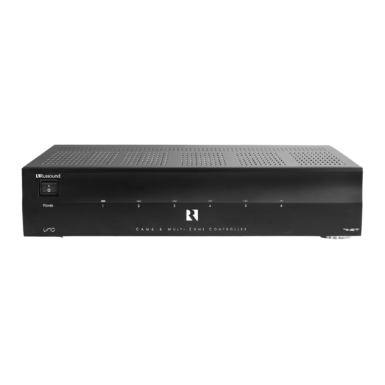
USER COMPONENT GUIDE CAM6.6 Controller-Front Panel MAIN POWER SWITCH - Supplies power to the CAM6.6 ROOM LED ON/OFF INDICATORS - Indicates when a room is on (green) or off (red) Main Power and Zone Status The power switch for the CAM6.6 controller is “on” in the up position. Any active room (1-6) is indicated on the front of the controller by a green LED, which shows red when the room is inactive. -
Page 7: Uno-S1 Keypad
LCD PANEL - 5-character backlit display shows status of the room, source, volume, and more SOURCE SELECT BUTTON - Scrolls through the sources directly connected to the CAM6.6. Press and hold brings up the USER MENU for loudness, bass, treble, etc. VOLUME UP/DOWN BUTTONS - Raises and lowers the volume for the room IR RECEIVER - Receives IR signals and passes them to the controller and source equip- ment. -
Page 8: Uno-S2 Keypad
USER COMPONENT GUIDE UNO-S2 Keypad CD PLAYER 1 LCD PANEL - 12-character backlit display shows status of the room, source, volume, and more SOURCE SELECT BUTTON - Scrolls through the sources directly connected to the CAM6.6. Press and hold brings up the USER MENU for loudness, bass, treble, etc. VOLUME UP/DOWN BUTTONS - Raises and lowers the volume for the room IR RECEIVER - Receives IR signals and passes them to the controller and source equip- ment. -
Page 9: Uno-Ts2 Touchscreen
IR RECEIVER - Receives IR signals and passes them to the controller and source equip- ment. Also used when operating the touchscreen by using the SRC2 remote TOUCHSCREEN - Full color resistive touchscreen with multi-sound feedback. Screen can be programmed to go blank after a period of inactivity. Touching the screen any- where reactivates it. -
Page 10: Src2 Remote Control
(e.g., VCR, DVD, or CD player) with these buttons. SOURCE - Directly select sources connected to the Russound controller while in the Russound mode. F1 AND F2 BUTTONS - Selects and saves Favorite 1 or Favorite 2 preset selections. -
Page 11: Operation
Room On/Off Press and release to turn on the UNO System Keypad. This also turns on the corre- sponding CAM6.6’s room, and any presets previ- ously assigned will be activated, including set- tings for bass, volume, last source selected, etc. Press and release to turn off the UNO System Keypad. -
Page 12: Uno-S1 User Menu
USER USER MENU SETTINGS UNO-S1 User Menu Operation The User Menu allows the user to adjust the audio properties and control functions of a par- ticular room. To enter or exit the User Menu, press and hold during normal operation. The following keys are used to navigate and make changes while using the User Menu: Press and hold to adjust feature setting... -
Page 13: Uno-S2 Keypad Button Function
Room On/Off Press and release to turn on the UNO System Keypad. This also turns on the corre- sponding CAM6.6’s room, and any presets previ- ously assigned will be activated, including set- tings for bass, volume, last source selected, etc. Press and release to turn off the UNO System Keypad. -
Page 14: Uno-S2 User Menu
USER USER MENU SETTINGS UNO-S2 User Menu Operation The User Menu allows the user to adjust the audio properties and control functions of a par- ticular room. The following keys are used to navigate and make changes while using the User Menu: To enter the User Menu, press and hold during normal operation. -
Page 15: Uno-Ts2 Touchscreen Button Function
Room On/Off To turn on the room and the touchscreen, touch the UNO-TS2 screen anywhere, or press and release the power button. Any presets previously assigned will be activated, including settings for bass, volume, last source selected, etc. Press and release the power button to turn off the touch- screen, and to put the room into a standby state. -
Page 16: Uno-Ts2 - Setting Preferences
USER USER MENU SETTINGS UNO-TS2 - Setting Preferences The Options button on the home screen brings up room setting options and screen adjustments. (For more detailed information, consult the UNO-TS2 Instruction Manual) Features Turn On Volume - This sets the room’s default vol- ume when the room is turned on. -
Page 17: Internal Source - Am/Fm Tuner
UNO-S1 Keypad Control of Tuner Selecting the tuner On the UNO-S1 keypad, press AM/FM tuner by choosing the tuner’s preas- signed source number (1). Selecting the desired frequency Press and hold to activate manual tuning. Once active, press 102.5 INTERNAL SOURCE - AM/FM TUNER through frequencies. -
Page 18: Uno-S2 Keypad Control
USER INTERNAL SOURCE - AM/FM TUNER UNO-S2 Keypad Control UNO-S2 Keypad Control of Tuner Selecting the tuner On the UNO-S2 keypad, press AM/FM tuner by choosing the tuner’s preas- signed source number (1). Selecting the desired band Push to toggle between AM band and FM band reception. - Page 19 TUNER SELECTION - Select source number assigned to AM/FM TUNER (1) TUNE UP/DOWN - Used for manual station selection SELECT - Selects AM or FM band SEEK - (press) Seeks next higher tuned station INTERNAL SOURCE - AM/FM TUNER 92.5 MHz FM SCAN - (press and hold) Scans through tuned sta- tions with 5-second preview before next station MUTE - Mutes/unmutes tuner audio output...
-
Page 20: Uno-Ts2 Touchscreen Control
New presets can be saved over existing presets using the same method. Note: If the UNO-TS2 is powered on before the Russound Tuner is turned on, existing preset names may not appear until after the tuner’s boot up procedure is complete (less than a minute). -
Page 21: Uno-Ts2 Touchscreen Control
Banks and Memory Presets Example of Bank and Preset screen for Russound Tuner Numeric Station/Channel Selection Example of numeric station selection screen for Russound Tuner AM/FM Tuner Advanced Features Example of AM/FM tuner screen INTERNAL SOURCE - AM/FM TUNER UNO-TS2 Touchscreen Control Tuner 1 Dad’s Music... -
Page 22: Src2 Remote Control
USER INTERNAL SOURCE - AM/FM TUNER SRC2 Remote Control SRC2 Control of Tuner Selecting the tuner To select the tuner, push sources and choose the source number preassigned to the AM/FM tuner (1), or use the UNO numeric source inputs at the bottom of the SRC2. Selecting the desired band Push to toggle between AM/FM reception. - Page 23 RUSSOUND SELECTION - “R” must be the selected source for control of the CAM6.6 and any connected compo- nents. Select “R” before sending SRC2 remote commands. INTERNAL SOURCE - AM/FM TUNER SRC2 Remote Control POWER - Power managed by CAM6.6...
-
Page 24: Installer Section
INSTALLER SECTION Getting Started Includes an installation overview, including tools needed and connection tips. Component Guides Reviews front and back panel features of the CAM6.6 controller and the UNO keypads. Keypad Installation Explains UNO keypad installation and wiring. Making Connections Details front and back panel connections of the controller and the keypads. -
Page 25: Getting Started
• Check for any visible signs of damage. If you encounter any concealed damage, con- sult your Russound dealer before proceeding to install the unit. • Retain the sales receipt as it establishes the duration of the limited warranty and provides information for insurance purposes. -
Page 26: Component Guide
INSTALLER COMPONENT GUIDE CAM6.6 Controller-Rear Panel RNET LINK IN AND LINK OUT - Links multiple CAM6.6’s, also links future Russound components that are RNET compatible RS-232 INTERFACE - The RS-232 Interface allows the zones to be controlled by PC or other devices that have an RS-232 Interface. The RS-232 Interface also allows for firmware updates and programming. -
Page 27: Cam6.6 Controller Rear Panel
OPTIONAL INTERNAL SOURCE - Factory installed optional internal source, AM/FM radio module AC 240V-AC 110V Switch - Switches A/C input voltage between 110VAC and 240VAC AC 120/240 INPUT - Grounded 3-terminal plug detachable power cord connection for the CAM6.6 FUSE HOLDER - Holds a replaceable fuse for A/C input connection 110VAC operation - F 3A H 250V, 240VAC operation;... -
Page 28: Uno Keypad Os Update Port
UNO Keypad Update Port Software Update If a keypad update is released, it will be available online at www.russound.com through the Document Center, under RNET Systems. Before starting the update procedure, download updates to a PC and con- nect the correct programming cable from the PC to the OS update port on the front of the keypad. -
Page 29: Uno Keypad Rear Panel
UNO-S2 EXTERNAL IR RECEIVER IN CONNECTOR - Connection for an external IR Receiver OS UPDATE JUMPER - Selects mode “Run” (one pin covered) or “OS Update” (two pins covered). Jumper setting must be in “Run” position for keypad operation. RESET BUTTON - (UNO-S2) Reset whenever changing from RUN to OS update (UNO-TS2) Reset after touchscreen firmare update 110 PUNCHDOWN CONNECTOR - Termination for CAT-5 connection between the UNO Keypad and the CAM6.6 controller... -
Page 30: Wiring Instructions
INSTALLER WIRING INSTRUCTIONS Wire Length To determine the amount of CAT-5 wire required for the system installation, first decide how many keypads will be used, then determine the distance between each intended keypad location to the intended CAM6.6 location. The maximum recommended wire run length is 250 feet for each UNO keypad. -
Page 31: Uno-S2 Ir Receiver Connection
The UNO-S2 keypad has an External IR Receiver IN terminal for connecting an external IR receiv- er such as the Russound SaphIR 858, 862 Eye, or 860 Phantom. Use 2 twisted pair wire with Back of Russound 858 INSTALLER WIRING INSTRUCTIONS... -
Page 32: Keypad Installation
INSTALLER UNO KEYPAD INSTALLATION Keypad Location The best infrared remote performance is achieved with the keypad away from any direct sunlight, plasma TV, and low voltage lighting controls. Also consider convenience when choosing a location. Choose a place that is easily seen from the posi- tion where a person is most likely to be located. -
Page 33: Making Connections
The UNO System Keypad Ports are located on the back of the CAM6.6 in the top left of center. Connections made at the UNO Keypad Ports are made using CAT-5 T568A RJ-45 wire configura- tion. CAT-5 is color-coded for ease of installa- tion. -
Page 34: Source Audio Input Connections
CAM6.6. This IR port is directly above the Source Audio Input Connections. 1. Using an IR emitter (the Russound 845.1 is recommended) attach the end of the emitter with the 1/8 the source input. -
Page 35: Common Ir Input Connection
857 IR connecting block MAKING CONNECTIONS Common IR Connection IR emitter with a 1/8’’ plug. The Russound 845.1 single IR emitter is recommended, or use an IR connecting block such as the Russound 857 which allows multiple units to be controlled through the COM IR Port. -
Page 36: Speaker Connections
INSTALLER MAKING CONNECTIONS Speaker Connections The speakers are connected to the CAM6.6 using modular snap connectors. Each of these color-coded connectors is designated for the speaker set of a particular amplified zone. To avoid confusion, connect one zone speaker set at a time starting with Zone 1, taking care to keep zone and speaker wire identities straight. -
Page 37: Zone Fixed/Variable Audio Output
INSTALLER MAKING CONNECTIONS Zone Fixed/Variable Audio Outputs The fixed or variable audio outputs can be used if additional amplification is desired (e.g., Russound R235LS two-channel amplifier). Use quality RCA signal cables to ensure a constant quality audio signal. CAM6.6... -
Page 38: 12Vdc Home Theater Trigger In/Out
12VDC 100mA Trigger Out The 12VDC 100mA trigger out can be used to engage any 12VDC trigger device or component such as the Russound ACT-1 triggered outlet. The connections for the trigger out are made using a two-conductor cable with 1/8” male mini-plug jacks at each end. -
Page 39: 12Vdc Mute Trigger In/Out
12VDC Mute Trigger In When 12VDC is applied to the Mute Trigger In, the system will fully mute any source that is con- nected to the Source Audio Input. The connec- tions for the trigger are made using a two-con- ductor cable with 1/8”... -
Page 40: Rnet Link In/Out
IR repeating signal lines. The RNET Link In and Link Out is also used to connect the CAM6.6 to other Russound prod- ucts with RNET. Note: If two or more CAM6.6 or CAV6.6 con-... -
Page 41: Rs-232 Interface
CAM6.6 and uses a DB-9 cable connection. DB9 Cable INSTALLER MAKING CONNECTIONS RS-232 Interface For RS-232 protocol and the backup PC applica- tion, go to www.russound.com, Document Center . Under RNET Systems, look under the heading for Technical Documents. NTERFACE CAM6.6... -
Page 42: Am/Fm Tuner Antennas
INSTALLER MAKING CONNECTIONS Optional Internal Source - AM/FM Tuner Antennas AM Antenna Connect the included loop antenna for AM recep- tion to the Optional Internal Source panel, attach- ing the GND (ground) and AM ends to the appro- priately marked connections. FM Antenna Attach the included FM antenna for FM reception to the Optional Internal Source panel by pushing... - Page 43 Connecting an Alternate Outdoor Antenna for AM/FM The diagram below depicts a suggested installa- tion option of an alternate outdoor FM antenna and AM antenna. For best performance for AM reception, it is rec- ommended to use an external outdoor or attic- mounted long wire antenna for best performance Optional Internal Source - AM/FM Tuner Antennas for AM reception.
- Page 44 INSTALLER MAKING CONNECTIONS Grounding Outdoor Antennas Antenna Lead In Wire Grounding Conductors Ground Clamps Grounding an Outdoor Antenna If the tuner is used with an outdoor antenna, the antenna must be grounded against static charges and voltage surges. Consult the instruc- tions that came with the antenna or contact the antenna manufacturer for proper installation instructions.
-
Page 45: Initial Install Test
4. Check to see that the keypad is connected to the Zone #3 Keypad Port and verify the CAT-5 is properly terminated at both ends. If none of these steps produce successful results, call Russound Tech Support for further assistance. INSTALLER... -
Page 46: System Programming Overview
INSTALLER SYSTEM PROGRAMMING OVERVIEW This manual includes items that are designed to assist in the programming process. Forms (Pages 106-108) Three blank reproducible forms are included as planning tools when determining sources, settings and zone preferences. The Source and Zone Information forms and the Macro Editor form should be completed before programming and referred to during the installation menu process. -
Page 47: System Programming Overview
INSTALLER SYSTEM PROGRAMMING OVERVIEW 3. Basic Setup (SOURCE SETUP) (Pages 51-53) This procedure is mandatory to set up each source for keypad source control and is the cornerstone of the programming process. 4. Peripheral Setup (Pages 49-51) (FOR OPTIONAL INTERNAL SOURCE) This procedure provides setup and naming procedures for the tuner. -
Page 48: Installation Menu Overview
INSTALLER INSTALLATION MENU OVERVIEW There are three item types in the installation menu: “ Menu – Folder” that holds procedures and/or feature options. Procedure – A series of steps to perform a guided operation, such as configuring a button. Feature – The actual settings that will change the system configuration. -
Page 49: Peripheral Setup
The following items make up the Installation Menu: PERIPH SETUP (PerSu) SOURCE SETUP (SrcSu) CTRLR SETUP (CtlSu) POWER MGT (PwMgt) MACRO EDITOR (MacEd) PERIPH SETUP (PerSu) Note: For CAM6.6, Peripheral Setup is not applicable. “N N o o t t A A v v a a i i l l ” shows on the keypad. Peripheral Setup allows the CAM6.6’s optional internal source to be configured. - Page 50 INSTALLER INSTALLATION MENU 2. BANK NAME – (BnkNm) CONTROLLR ID (CtlId) This procedure is used to identify the controller(s) that the tuner will respond to. See Periph Setup - Flow Chart on page 65 1. Controller:# – (CtlId) 2. All controllers – (All) REGION (Rgion) This procedure assigns either US or Euro frequency display to the tuner.
-
Page 51: Source Setup
SYSTEM INFO (SInfo) System Info shows the tuner’s manufacturing build properties. See Periph Setup - Flow Chart on page 65 BUILD TIME (BTime) BUILD DATE (BDate) 1. BUILD TIME (BTime) 2. BUILD DATE (BDate) 3. VERSION (Ver) SOURCE SETUP (SrcSu) Source Setup allows the system’s sources to be configured. - Page 52 INSTALLER INSTALLATION MENU 2. SOURCE NAME – (Name) 3. COMMAND TYPE – (CmdTp) a. Selected: Learned IR (LrnIR) i. LEARNED SRC – (LnSrc) ii. TEMPLATE TYP – (TType) b. Selected: Unassigned (Unasg) c. All Other Selections: 4. DEVICE CODE – (DevCd) 5.
- Page 53 9. AUTO PLAY? – (AtoPl) 10. SAVE CHANGES? – (Save?) KEY CONFIG (KeyCf) Key Configuration defines zone-specific key functions for each source. See Key Config. - Flow Chart on page 67 1. ZONE NUM – (Zone#) 2. SOURCE NUM – (Src #) 3.
- Page 54 INSTALLER INSTALLATION MENU i. MACRO - (Macro) ii. MACRO ID – (MacID) e. All Other Selections: 7. DEVICE CODE – (DevCd) 8. KEY FUNCTION – (KeyFn) 9. SAVE CHANGES? – (Save?) SOURCE NAMES (SrcNm) This procedure allows the installer to customize the source names for the sources attached to the CAM6.6.
- Page 55 1. SOURCE NUM – (Src #) 2. USE NUM IR? – (NumIR) 3. HIGHEST NUM – (High#) 4. NUMERIC TEXT – (NmTxt) 5. PREFIX CMD – (Prefx) 6. COMMAND TYPE – (CmdTp) a. Selected: Learned IR (LrnIR) i. LEARNED SRC – (LnSrc) b.
- Page 56 INSTALLER INSTALLATION MENU 9. SUFFIX CMD – (Sufix) 10. COMMAND TYPE – (CmdTp) a. Selected: Learned IR (LrnIR) i. LEARNED SRC – (LnSrc) b. Selected: Unassigned (Unasg) c. Selected: Default (Deflt) d. Selected: Macro: (Macro) i. MACRO - (Macro) ii. MACRO ID – (MacID) e.
- Page 57 2. COMMAND TYPE – (CmdTp) a. Selected: Learned IR (LrnIR) i. LEARNED SRC – (LnSrc) b. Selected: Unassigned (Unasg) c. Selected: Default (Deflt) d. Selected: Macro: (Macro) i. MACRO - (Macro) ii. MACRO ID – (MacID) e. All Other Selections: 3.
-
Page 58: Zone Setup
INSTALLER INSTALLATION MENU ZONE SETUP (ZonSu) NOTE: This procedure should be performed using the keypad installed in the zone to be configured. See Zone Setup - Flow Chart on page 71 Zone Setup allows the installer to adjust properties of the UNO Keypad controlled CAM6.6 zone. This series of menus allows the system’s zones to be configured for these properties: ZON VOL TRIM (ZonVT) MASTER ENABL (MstEn) -
Page 59: Power Management
2. FACTORY INIT (FInit) POWER MANAGEMENT (PwMgt) The CAM6.6 is capable of managing the power state of the connected source equipment. The power management is configured on a source-by-source basis. All sources that have power management enabled are initialized by a “POWER ON” command or macro. - Page 60 INSTALLER INSTALLATION MENU c. Selected: Default (Deflt) d. Selected: Macro: (Macro) i. MACRO - (Macro) ii. MACRO ID – (MacID) e. All Other Selections: 4. DEVICE CODE – (DevCd) 5. KEY FUNCTION – (KeyFn) 6. POWER OFF CMD – (OfCmd) 7.
-
Page 61: Learn Ir
e. All Other Selections: 8. DEVICE CODE – (DevCd) 9. KEY FUNCTION (f) – (KeyFn) 10. SAVE CHANGES? (f) – (Save?) LEARN IR (LrnIR) This procedure allows IR commands to be learned into the system and be centrally stored in the main controller to let the system access the same IR codes that operate the source equipment. -
Page 62: Macro Editor
INSTALLER INSTALLATION MENU MACRO EDITOR (MacEd) This procedure is used to create a sequence of commands that are launched with one key touch or other event. Up to 132 macros can be created for the system, and each macro can contain up to 10 commands including other macros and delays. -
Page 63: System Info
5. DEVICE CODE – (DevCd) 6. KEY FUNCTION – (KeyFn) SYSTEM INFO (SInfo) System Info allows the installer to view the controller’s manufacturing build properties. See System Info - Flow Chart on page 76 #CONTROLLERS (#Ctls) BUILD TIME (BTime) 1. #CONTROLLERS (#Ctls) 2. -
Page 64: Setup Menu Flow Charts
INSTALLER SETUP MENU FLOW CHARTS... -
Page 65: Peripheral Setup: Controller Id, Region, Factory Init, System Info
INSTALLER SETUP MENU FLOW CHARTS... -
Page 66: Basic Setup
INSTALLER SETUP MENU FLOW CHARTS... -
Page 67: Key Configuration
INSTALLER SETUP MENU FLOW CHARTS... -
Page 68: Source Names/Volume Trim
INSTALLER SETUP MENU FLOW CHARTS... -
Page 69: Numeric Ir
INSTALLER SETUP MENU FLOW CHARTS... -
Page 70: Source Select Command/Number Of Sources
INSTALLER SETUP MENU FLOW CHARTS... -
Page 71: Zone Setup
INSTALLER SETUP MENU FLOW CHARTS... -
Page 72: Controller Setup
INSTALLER SETUP MENU FLOW CHARTS... -
Page 73: Power Management
INSTALLER SETUP MENU FLOW CHARTS... -
Page 74: Learn Ir
INSTALLER SETUP MENU FLOW CHARTS... -
Page 75: Macro Editor
INSTALLER SETUP MENU FLOW CHARTS... -
Page 76: System Info
INSTALLER SETUP MENU FLOW CHARTS... -
Page 77: Keypad Diagnostics Menu
The Diagnostics Menu allows the installer to run a diagnostic check on the keypad and to verify the firmware version. The Diagnostics Menu also contains the update firmware procedure for updating the UNO-S1 and UNO-S2’s firmware. To access the Diagnostics Menu, press and hold the Setup button on the right side of the keypad until “DIAGNOSTICS”... -
Page 78: Ir Device Code List
INSTALLER IR DEVICE CODES Device Codes for TVs: Admiral 0093, 0463 Advent 0761, 0842 Aiko 0092 Akai 0030, 0672, 0702, 0812 Albatron 0700, 0843 America Action 0180 Anam 0180 0030 Apex Digital 0748, 0765, 0767, 0879, 1943 Audiovox 0451, 0180, 0092, 0623 Bell &... - Page 79 Device Codes for Cable: (cont’d) Starcom 0003 Supercable 0276 Supermax 0883 Torx 0003 Toshiba 0000 Tristar 0883 0883 Viewmaster 0883 Vision 0883 Vortex View 0883 Zenith 0000, 0525, 0899 Device Codes for Video Acc: 1272 Alienware 1272 CyberPower 1272 D-Link 1554 Escient 1151, 1371, 1370, 1373, 1372...
- Page 80 INSTALLER IR DEVICE CODES Device Codes for VCRs: (cont’d) Pulsar 0039 Quasar 0035, 0162 Radio Shack 0000 Radix 0037 Randex 0037 0060, 0240, 0042, 0149, 0880 Realistic 0035, 0037, 0048, 0047, 0000, 0104 ReplayTV 0616 Runco 0039 Samsung 0045, 0240 Sanky 0048, 0039 Sansui...
- Page 81 0892 Lenoxx 1561 Marantz 0892, 1491 Motorola 1464 Omnifi 1605 Optimus 0395 Philips 0892 Polk Audio 0892 Realistic 0395 Russound 1302 Sony 0159 Soundesign 0078 Victor 0331 Wards 0078 Yamaha 0354 Device Codes for CD Players: Aiwa 0157 Burmester 0420 Calif.
-
Page 82: Ir Keycode List
INSTALLER KEY CODES TV (HDTV) KEY FUNCTION UNO-S1 TV (HDTV) Volume Up VolUp Volume Down VolDn Mute Mute Channel Up Ch Up Channel Dn Ch Dn Power Power Enter Enter Prev Channel PrvCh TV/Video TVVid TV/VCR TVVCR Learned Only A / B TV/DVD TVDVD Learned Only TV/LD... - Page 83 KEY FUNCTION UNO-S1 TV (HDTV) Off, Power On/Off Learned Only Learned Only Learned Only Learned Only Learned Only Learned Only Bright Brght Learned Only Learned Only Close Close Learned Only Open Open Learned Only Halt Halt Learned Only AM/FM AM/FM Learned Only Learned Only Disk Up DiskU...
- Page 84 INSTALLER KEY CODES CABLE KEY FUNCTION UNO-S1 CABLE Volume Up VolUp Volume Down VolDn Mute Mute Channel Up Ch Up Channel Dn Ch Dn Power Power Enter Enter Prev Channel PrvCh TV/Video TVVid TV/VCR TVVCR A / B TV/DVD TVDVD TV/LD TV LD Input...
- Page 85 KEY FUNCTION UNO-S1 CABLE Off, Power On/Off Learned Only Learned Only Learned Only Learned Only Learned Only Learned Only Bright Brght Learned Only Learned Only Close Close Learned Only Open Open Learned Only Halt Halt Learned Only AM/FM AM/FM Learned Only Learned Only Disk Up DiskU...
- Page 86 INSTALLER KEY CODES VIDEO ACC KEY FUNCTION UNO-S1 VIDEO ACC Volume Up VolUp Volume Down VolDn Mute Mute Channel Up Ch Up Channel Dn Ch Dn Power Power Enter Enter Prev Channel PrvCh TV/Video TVVid TV/VCR TVVCR A / B TV/DVD TVDVD TV/LD...
- Page 87 KEY FUNCTION UNO-S1 VIDEO ACC Off, Power On/Off Learned Only Learned Only Learned Only Learned Only Learned Only Learned Only Bright Brght Learned Only Learned Only Close Close Learned Only Open Open Learned Only Halt Halt Learned Only AM/FM AM/FM Learned Only Learned Only Disk Up...
- Page 88 INSTALLER KEY CODES SAT/DSS KEY FUNCTION UNO-S1 SAT/DSS Volume Up VolUp Volume Down VolDn Mute Mute Channel Up Ch Up Channel Dn Ch Dn Power Power Enter Enter Prev Channel PrvCh TV/Video TVVid TV/VCR TVVCR Learned Only A / B TV/DVD TVDVD Learned Only TV/LD...
- Page 89 KEY FUNCTION UNO-S1 SAT/DSS Off, Power On/Off Learned Only Learned Only Learned Only Learned Only Learned Only Learned Only Bright Brght Learned Only Learned Only Close Close Learned Only Open Open Learned Only Halt Halt Learned Only AM/FM AM/FM Learned Only Learned Only Disk Up DiskU...
- Page 90 INSTALLER KEY CODES KEY FUNCTION UNO-S1 VCR Volume Up VolUp Volume Down VolDn Mute Mutte Channel Up Ch Up Channel Dn Ch Dn Power Power Enter Enter Prev Channel PrvCh TV/Video TVVid TV/VCR TVVCR Learned Only A / B TV/DVD TVDVD Learned Only TV/LD TV LD...
- Page 91 KEY FUNCTION UNO-S1 VCR Off, Power On/Off Learned Only Learned Only Learned Only Learned Only Learned Only Learned Only Bright Brght Learned Only Learned Only Close Close Learned Only Open Open Learned Only Halt Halt Learned Only AM/FM AM/FM Learned Only Learned Only Disk Up DiskU...
- Page 92 INSTALLER KEY CODES LASER DISC KEY FUNCTION UNO-S1 LASER DISC Volume Up VolUp Volume Down VolDn Mute Mute Channel Up Ch Up Channel Dn Ch Dn Power Power Enter Enter Prev Channel PrvCh TV/Video TVVid TV/VCR TVVCR Learned Only A / B TV/DVD TVDVD Learned Only TV/LD...
- Page 93 KEY FUNCTION UNO-S1 LASER DISC Off, Power On/Off Learned Only Learned Only Learned Only Learned Only Learned Only Learned Only Bright Brght Learned Only Learned Only Close Close Learned Only Open Open Learned Only Halt Halt Learned Only AM/FM AM/FM Learned Only Learned Only Disk Up...
- Page 94 INSTALLER KEY CODES KEY FUNCTION UNO-S1 DVD Volume Up VolUp Volume Down VolDn Mute Mute Channel Up Ch Up Channel Dn Ch Dn Power Power Enter Enter Prev Channel PrvCh TV/Video TVVid TV/VCR TVVCR Learned Only A / B TV/DVD TVDVD Learned Only TV/LD TV LD...
- Page 95 KEY FUNCTION UNO-S1 DVD Off, Power On/Off Learned Only Learned Only Learned Only Learned Only Learned Only Learned Only Bright Brght Learned Only Learned Only Close Close Learned Only Open Open Learned Only Halt Halt Learned Only AM/FM AM/FM Learned Only Learned Only Disk Up DiskU...
- Page 96 INSTALLER KEY CODES RECEIVER KEY FUNCTION UNO-S1 RECEIVER Volume Up VolUp Volume Down VolDn Mute Mute Channel Up Ch Up Channel Dn Ch Dn Power Power Enter Enter Prev Channel PrvCh TV/Video TVVid TV/VCR TVVCR A / B TV/DVD TVDVD TV/LD TV LD Input...
- Page 97 KEY FUNCTION UNO-S1 RECEIVER Off, Power On/Off Learned Only Learned Only Learned Only Learned Only Learned Only Learned Only Bright Brght Learned Only Learned Only Close Close Learned Only Open Open Learned Only Halt Halt Learned Only AM/FM AM/FM Learned Only Learned Only Disk Up DiskU...
- Page 98 INSTALLER KEY CODES AMP/MISC AUDIO KEY FUNCTION UNO-S1 AMP/MISC AUDIO Digit 1 Digit 2 Digit 3 Digit 4 Digit 5 Digit 6 Digit 7 Digit 8 Digit 9 Digit 0 Volume Up VolUp Volume Up Volume Down VolDn Volume Down Mute Mute Mute...
- Page 99 KEY FUNCTION UNO-S1 AMP/MISC AUDIO Off, Power On/Off Learned Only Learned Only Learned Only Learned Only Learned Only Learned Only Bright Brght Learned Only Learned Only Close Close Learned Only Open Open Learned Only Halt Halt Learned Only AM/FM AM/FM Learned Only Learned Only Disk Up...
- Page 100 INSTALLER KEY CODES KEY FUNCTION UNO-S1 CD Volume Up VolUp Volume Down VolDn Mute Mute Channel Up Ch Up Channel Dn Ch Dn Power Power Enter Enter Prev Channel PrvCh TV/Video TVVid TV/VCR TVVCR Learned Only A / B TV/DVD TVDVD TV/LD TV LD...
- Page 101 KEY FUNCTION UNO-S1 Off, Power On/Off Learned Only Learned Only Learned Only Learned Only Learned Only Learned Only Bright Brght Learned Only Learned Only Close Close Learned Only Open Open Learned Only Halt Halt Learned Only AM/FM AM/FM Learned Only Learned Only Disk Up DiskU...
- Page 102 INSTALLER KEY CODES HOME CONTROL KEY FUNCTION UNO-S1 HOME CONTROL Volume Up VolUp Volume Down VolDn Mute Mute Channel Up Ch Up Channel Dn Ch Dn Power Power Enter Enter Prev Channel PrvCh TV/Video TVVid TV/VCR TVVCR A / B TV/DVD TVDVD TV/LD...
- Page 103 KEY FUNCTION UNO-S1 HOME CONTROL Off, Power On/Off Learned Only Learned Only Learned Only Learned Only Learned Only Learned Only Bright Brght Learned Only Learned Only Close Close Learned Only Open Open Learned Only Halt Halt Learned Only AM/FM AM/FM Learned Only Learned Only Disk Up...
-
Page 104: Source Names
INSTALLER SOURCE NAMES UNO-S1 UNO-S2 Aux 1 AUX 1 Aux 2 AUX 2 Blues Blues Cable Cable Cbl 1 Cable 1 Cbl 2 Cable 2 Cbl 3 Cable 3 CDCh CD Changer CDCh1 CD Changer 1 CDCh2 CD Changer 2 CDCh3 CD Changer 3 CD Player... -
Page 105: Source Names
UNO-S1 UNO-S2 RepTV ReplayTV Rock Rock Satellite Sat 1 Satellite 1 Sat 2 Satellite 2 Sat 3 Satellite 3 SatRd Sat Radio Src 1 Source 1 Src 2 Source 2 Src 3 Source 3 Src 4 Source 4 Src 5 Source 5 Src 6 Source 6... -
Page 106: Source Information Form
INSTALLER SETUP FORMS... -
Page 107: Zone Information Form
INSTALLER SETUP FORMS... -
Page 108: Macro Editor Form
INSTALLER SETUP FORMS... -
Page 109: Sample Configurations
Sharing a single CAM6.6T (internal tuner) with multiple controllers This arrangement can support up to six CAM6.6 units for up to 36 zones/6 sources. Each additional CAM6.6 must have an incremental Controller ID # and RNET link. Audio from the source tuner can be split if shared by all controllers. - Page 110 SAMPLE CONFIGURATIONS MULTIPLE CONTROLLERS WITH ST2 DUAL TUNER Sharing an ST2 Dual Tuner with multiple CAM6.6 con- trollers (no built-in tuners) The configuration below is suitable for 7 to 12 zones that can all access the ST2 Dual Tuner. This configura- tion uses RCA “Y”...
- Page 111 Sharing an ST2 Dual Tuner with multiple CAM6.6 con- trollers (with and without tuners) The configuration below is suitable for 7 to 12 zones that can access the ST2 Dual Tuner and the CAM6.6T tuner. This configuration uses RCA “Y” cables from the ST2 Tuner source outputs to connect to both CAM6.6 source inputs.
-
Page 112: Technical Specifications
TECHNICAL SPECIFICATIONS Dimensions: 17"W x 12"D x 3.5"H (43 x 30.5 x 9 cm) Weight: 18 lbs. (8.1 kg) Power Supply: 110 or 240 VAC Fuse Rating: 110V input; F3A H 250V US and Canada 240V input; T1.25A H 250V Europe Frequency Response: 20Hz-20kHz +/- 1dB Watts per channel:... - Page 113 In these cases, repairs will be made on the basis of the retail value of the parts and labor. To return for repairs, the unit must be shipped to Russound at the owner's expense, along with a note explaining the nature of service required. Be sure to pack the unit in a corrugated container with at least three (3) inches of resilient material to protect the unit from damage in transit.
-
Page 114: Warranty
NOTES... - Page 115 NOTES...
- Page 116 All trademarks are property of their respective owners. 5 Forbes Road, Newmarket, NH 03857 Specifications subject to change without notice. tel 603.659.5170 • fax 603.659.5388 Russound is not responsible for typographical errors or omissions. e-mail: tech@russound.com For use with CAM6.6 Rev. 1 Hardware www.russound.com 28-0111 Rev.