
Related Manuals for Bosch LA3-VARI-B


Summary of Contents for Bosch LA3-VARI-B
- Page 1 VARI‑directional array LA3‑VARI‑B, LA3‑VARI‑BH, LA3‑VARI‑E, LA3‑VARI‑CM, LA3‑VARI‑CS Installation manual...
-
Page 3: Table Of Contents
Connecting the PC to the VARI Entering the venue parameters VARI configuration procedure 6.4.1 Control parameters 6.4.2 Ranges of adjustment 6.4.3 Other VARI parameters 6.4.4 Applying and saving the settings Bosch Security Systems B.V. Installation manual 2018.06 | V1.3 |... -
Page 4: En | Table Of Contents
| Table of contents VARI-directional array 6.4.5 Loading a previously saved settings file Technical Data 2018.06 | V1.3 | Installation manual Bosch Security Systems B.V. -
Page 5: Safety
Council for adjustment of legal requirements. Furthermore the products comply with the rules and regulations from 30 August 1995 referring to the electromagnetic compatibility of devices. Bosch VARI-directional Arrays bearing the CE label comply with the following harmonised or national standards:... -
Page 6: Introduction
This installation manual describes the recommended installation procedure for the Bosch VARI range of line arrays. The Bosch VARI is a DSP-based active line array. As well as loudspeaker drivers, the VARI base units, LA3-VARI-B, LA3-VARI-BH and LA3-VARI-E, contain a mains‑powered electronics module consisting of a multi‑channel amplifier and a Digital Signal... -
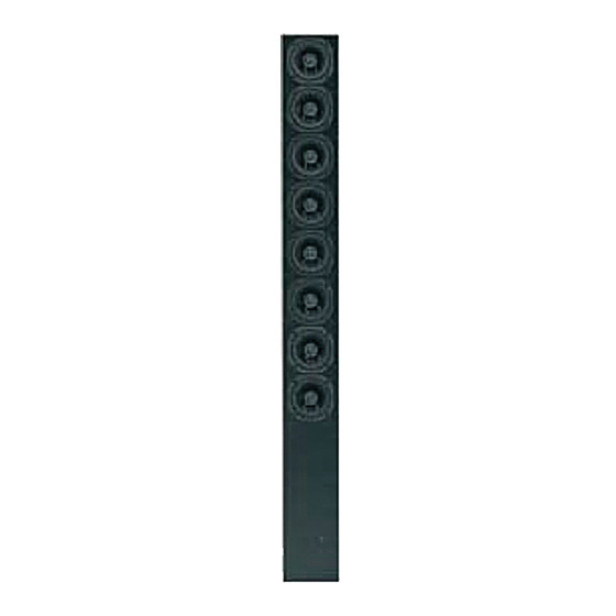
Page 7: System Overview
VARI-directional array System Overview | en System Overview The Bosch VARI product range consists of three line array variants, the configuration software and an optional CobraNet® module: – LA3-VARI-B : VARI Base unit. – LA3-VARI-BH : VARI Base unit with extended HF response. - Page 8 | System Overview VARI-directional array Figure 3.1: VARI overview (grilles removed for identification) 2018.06 | V1.3 | Installation manual Bosch Security Systems B.V.
- Page 9 A VARI‑CS Configuration Set can be used repeatedly, on multiple installations. Bosch can accept no responsibility for the correct functioning of any other type of computer interface; the use of OEM interfaces is not recommended.
-
Page 10: What's In The Packaging
USB to RS-485 interface, with manual Hardware interface USB cable, 1.8 m PC-to-interface cable (USB Type A to USB Type B) RS-485 cable, 5 m Interface-to-VARI cable (5-pin Phoenix to 5-pin Phoenix) 2018.06 | V1.3 | Installation manual Bosch Security Systems B.V. -
Page 11: Installation
- i.e., avoid mounting near columns, external room corners or ceiling infrastructure items such as air conditioning, lighting units, and the like. Bosch Security Systems B.V. Installation manual 2018.06 | V1.3 |... -
Page 12: Power, Signal And Control Cables
It will generally be necessary to mount the loudspeaker in position and feed the cables through the rear cable access hole before the cables are terminated. Connection Required? Cable type Section AC Mains supply Always required 3-core mains cable AC mains supply, page 13 2018.06 | V1.3 | Installation manual Bosch Security Systems B.V. -
Page 13: Ac Mains Supply
Refer to section Line level input 1 (4) and 2 (5), page 25 and 100 V input 1 (6) and 2 (7), page 25 for wiring details. Bosch Security Systems B.V. Installation manual 2018.06 | V1.3 |... -
Page 14: Backup Dc Power Supply
Capacitance (core to screen) 72.5 pF/m DC resistance (core) 78.7 ohms/km DC resistance (screen) 59.1 ohms/km Refer to section RS-485 network in (8) and thru (9), page 26 for wiring details. 2018.06 | V1.3 | Installation manual Bosch Security Systems B.V. -
Page 15: Cobranet® Input
(shields). Since the RS‑485 interface is optically isolated (to prevent ground loops), this ground has no relation to the chassis ground. It should not be connected to any other ground pin on the chassis. Bosch Security Systems B.V. Installation manual 2018.06 | V1.3 |... -
Page 16: Adding Vari-E Extension Units
“first” extension unit (that attached to the base unit) will have to be repositioned in an identical manner. 2018.06 | V1.3 | Installation manual Bosch Security Systems B.V. - Page 17 (1, 2, 3). This procedure will probably need a second person to steady the base unit; take care not to mate the connectors until the shells are accurately aligned, to avoid bending any pins on the male connector. Bosch Security Systems B.V. Installation manual 2018.06 | V1.3 |...
- Page 18 D‑connector cover plate removed from the top of the base unit to the top of the extension unit (or the second extension unit if there is one). The line array is now ready for configuration; refer to Configuring the VARI, page 29. 2018.06 | V1.3 | Installation manual Bosch Security Systems B.V.
-
Page 19: Optional Cobranet® Module
A description of CobraNet® can be found on www.cobranet.info. Here also CobraNet® Discovery can be downloaded. This is the tool to discover and configure CobraNet® interfaces, including the VARI CobraNet® module. Bosch Security Systems B.V. Installation manual 2018.06 | V1.3 |... -
Page 20: Mechanical Installation
The brackets allow the VARI to be mounted on a flat wall or column. The number of brackets required to mount each configuration is as follows: 2018.06 | V1.3 | Installation manual Bosch Security Systems B.V. - Page 21 Firmly tighten all the screws. Close the hinged brackets so that the loudspeaker is in its correct orientation. Re‑check the verticality with a spirit level or similar levelling device. Bosch Security Systems B.V. Installation manual 2018.06 | V1.3 |...
- Page 22 | Installation VARI-directional array Figure 4.8: Mechanical dimensions in mm 2018.06 | V1.3 | Installation manual Bosch Security Systems B.V.
-
Page 23: Connector And Wiring Details
RS-485 network thru Input 1 (line level) External control input Input 2 (line level) Failure relay Input 1 (100 V) CobraNet®/Ethernet port * * Only present if CobraNet® module is fitted. Bosch Security Systems B.V. Installation manual 2018.06 | V1.3 |... -
Page 24: Ac Mains Input
Backup DC power supply input (2) Connector type: 2‑pole, 7.62 mm-pitch: Function +24 V Warning! Because the DC power supply current can be quite high, a minimum wire size of 2.5 mm2, or AWG12 must be used. 2018.06 | V1.3 | Installation manual Bosch Security Systems B.V. -
Page 25: Line Level Input 1 (4) And 2 (5
100 V line - Loudspeaker distribution systems in some territories use 70 V line as the standard; all references in the manual to “100 V line” can be taken as applying equally to 70 V line. Bosch Security Systems B.V. Installation manual 2018.06 | V1.3 |... -
Page 26: Rs-485 Network In (8) And Thru (9
PC running the VariControl software and a USB to RS‑485 converter, part of the VARI‑CS Configuration Set. All slave devices are wired in parallel, the master device is 2018.06 | V1.3 | Installation manual Bosch Security Systems B.V. -
Page 27: Cable Length
Star‑wiring of multiple VARI slaves to the master should be avoided. If star-wiring is needed, use a multi-port full duplex hub or multiple full duplex RS‑485 repeaters. Bosch Security Systems B.V. Installation manual 2018.06 | V1.3 |... -
Page 28: Failure Relay
(such as the supervised control inputs of Bosch Praesideo units) to be interfaced. Note that one side of each contact set is paralleled and brought out as the ‘C’ pin of the external connector. -
Page 29: Configuring The Vari
This section describes how to use the VARI-control software to create a data file - the configuration file - specific to the loudspeaker being installed. The VARI-control software can be downloaded from the Bosch Product Website: www.boschsecurity.com. The electronics section within the VARI base unit is very sophisticated and controls all aspects of the VARI unit’s operation. -
Page 30: Software Installation
During installation it is advised to use the default destination folder (\[Program files folder]\Bosch\DDA libraries); if another folder is specified during the installation, the VariControl Folder for DDA libraries should be adapted. -
Page 31: Connecting The Pc To The Vari
USB‑to‑RS485 converter Figure 6.2: USB‑to‑RS485 converter The USB‑to‑RS485 converter of the VARI‑CS contains an IC device from Future Technology Devices International Ltd. Driver software for this converter can be downloaded from: http://www.ftdichip.com/Drivers/VCP.htm Bosch Security Systems B.V. Installation manual 2018.06 | V1.3 |... -
Page 32: Entering The Venue Parameters
Network view, the individual settings of that unit are shown and can be changed. Following an example is shown (in off‑line mode) for the VARI‑B. Figure 6.4: Entering the venue parameters 2018.06 | V1.3 | Installation manual Bosch Security Systems B.V. -
Page 33: Vari Configuration Procedure
This is the mounting height of the loudspeaker, and is measured vertically height from floor level to the bottom of the base unit. The height is selectable in increments of 0.1 m. Bosch Security Systems B.V. Installation manual 2018.06 | V1.3 |... -
Page 34: Ranges Of Adjustment
10 degrees. Figure given is with End at maximum. The alternative SPL display shows the same computed data as a simple graph of SPL at ear level against distance. 2018.06 | V1.3 | Installation manual Bosch Security Systems B.V. -
Page 35: Other Vari Parameters
– Surveillance: This page permits configuration settings relating to the loudspeaker’s operation under various fault conditions to be made. – Other: Miscellaneous unit settings. Bosch Security Systems B.V. Installation manual 2018.06 | V1.3 |... -
Page 36: Applying And Saving The Settings
Preset options box in the Presets pane. The File name box in the Settings file pane specifies the location in which the settings file will be saved. The default folder is at C:\...\My Documents\Bosch\VariControl\Settings, and the default filename is vari_default.ini. Installers will generally wish to save the settings file(s) in a different location;... - Page 37 The settings file will be uploaded into the VARI speaker, and into VariControl so that the parameters are visible. Proceed with section Mechanical installation, page 20 in case the VARI is not mechanical mounted yet. Bosch Security Systems B.V. Installation manual 2018.06 | V1.3 |...
- Page 38 Vertical (adjustable) Software configurable Maximum throw: 20 m VARI‑B(H) 32 m VARI‑B(H)+E 50 m VARI‑B(H)+E+E Transducers VARI‑B 4” Full Range (8 x 1 driver) VARI‑BH 4” Coaxial (8 x 1 driver) VARI‑E 4” Full Range (4 x 2 drivers) 2018.06 | V1.3 | Installation manual Bosch Security Systems B.V.
- Page 39 Power save 13 / 4.5 W VARI‑B(H) 17 / 7 W VARI‑B(H)+E 19 / 9 W VARI‑B(H)+E+E Idle 18 / 8.5 W VARI‑B(H) 23 / 13 W VARI‑B(H)+E 28 / 17 W VARI‑B(H)+E+E Max. (Noise, CF 6 dB) 60 / 36 W VARI‑B(H) 97 / 75 W VARI‑B(H)+E 124 / 100 W VARI‑B(H)+E+E Power factor According to EN61000‑3‑2, class A Bosch Security Systems B.V. Installation manual 2018.06 | V1.3 |...
- Page 40 No failure = closed / Failure = open Max. 24 V, 100 mA Rating Contact 2 No failure = 10 k ohm / Failure = 20 k ohm Control voltage input 5 to 24 Vdc, optically isolated CobraNet RJ‑45, Ethernet 100 Mbps Interface 2018.06 | V1.3 | Installation manual Bosch Security Systems B.V.
- Page 41 RAL9007 (gray aluminum) Grill: VARI‑B(H) and -E RAL9006 (white aluminum) Environmental Operating temperature -25 °C to 55 °C (-13 °F to 131 °F) Storage and transport temperature -40 ºC to +70 ºC (-40 ºF to +158 ºF) Relative humidity <95 % Bosch Security Systems B.V. Installation manual 2018.06 | V1.3 |...
- Page 42 (with no input signal present). Maximum number that can be connected to one RS‑485 subnet, multiple subnets can be controlled by one host PC. 2018.06 | V1.3 | Installation manual Bosch Security Systems B.V.
- Page 44 Bosch Security Systems B.V. Torenallee 49 5617 BA Eindhoven Netherlands www.boschsecurity.com © Bosch Security Systems B.V., 2018...