
Related Manuals for Bosch Conettix B444-A


Summary of Contents for Bosch Conettix B444-A
- Page 1 Conettix Cellular Communicators B442/B443/B444/B444‑A/B444‑V Installation Manual...
-
Page 3: Table Of Contents
Conettix Cellular Communicators Table of contents | en Table of contents Cellular module introduction About documentation Bosch Security Systems, Inc. product manufacturing dates Component overview Installation Insert the SIM card Install the antenna Install the communicator Remove the communicator Diagnostic LED descriptions... -
Page 4: Cellular Module Introduction
All hardware and software product names used in this document are likely to be registered trademarks and must be treated accordingly. Bosch Security Systems, Inc. product manufacturing dates Use the serial number located on the product label and refer to the Bosch Security Systems, Inc. website at http://www.boschsecurity.com/datecodes/. 2020.02 | 04 | F.01U.345.070 Installation Manual Bosch Security Systems B.V. -
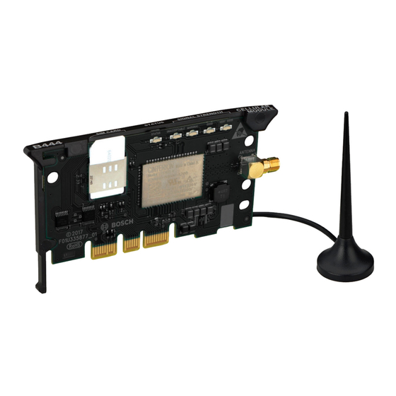
Page 5: Component Overview
1 - Module handle and support leg 2 - SIM card holder 3 - LEDs 4 - Threaded female SMA antenna connector 5 - Plug-in module retention clip opening 6 - PCM metal contacts Bosch Security Systems B.V. Installation Manual 2020.02 | 04 | F.01U.345.070... - Page 6 (sold separately). Failure to do so might cause poor signal strength. When using an external antenna such as the Bosch Multiband Antenna (B40-P, B40-MB25 or B40-MB50) connect the cable to the primary connector of the B444-A/V cellular module. You must also connect the supplied antenna to the secondary antenna connection.
- Page 7 B40-P/MB25/MB50 external antenna Connect antenna wire to the B40-P/MB25/MB50 antenna port (callout #3). Connect other end of B40-P/MB25/MB50 antenna wire to primary antenna port on B444- V/B444-A cellular module (callout #2). Bosch Security Systems B.V. Installation Manual 2020.02 | 04 | F.01U.345.070...
-
Page 8: Installation
Put the antenna cable through a knockout. Connect the antenna cable to the module. Make sure the antenna cable is inside the enclosure. Notice! Refer to the B444-A/B444-V Quick Installation Guide for detailed installation instructions. 2020.02 | 04 | F.01U.345.070 Installation Manual Bosch Security Systems B.V. - Page 9 Installation | en Figure 3.2: Installing the antenna Callout - Description 1 - Antenna routed through any knockout 2 - Antenna cable connected to the module Figure 3.3: B444-A/B444-V antenna installation Bosch Security Systems B.V. Installation Manual 2020.02 | 04 | F.01U.345.070...
-
Page 10: Install The Communicator
Put the support leg into the support hole labeled X. Refer to Figure 3.3. Align the PCB metal contacts with the on-board connector. Push the module into place. The retention clip snaps closed and secures the module in place. 2020.02 | 04 | F.01U.345.070 Installation Manual Bosch Security Systems B.V. - Page 11 Plug-in communicator interface installation Insert the communicator into the slot of the plug-in communicator interface. Push in until you feel it "click" into place. Figure 3.6: Communicator installation (B450 shown) Bosch Security Systems B.V. Installation Manual 2020.02 | 04 | F.01U.345.070...
-
Page 12: Remove The Communicator
3 - Plug-in communicator interface Remove the communicator Hold the plug-in module retention clip open. Hold the top corners of the module support handle with your other hand. Pull the module out. 2020.02 | 04 | F.01U.345.070 Installation Manual Bosch Security Systems B.V. -
Page 13: Diagnostic Led Descriptions
LED Trouble State: Indicates communicator is not powered, or some other trouble condition prohibits the communicator from controlling the STATUS LED. (Check for proper installation.) Tab. 4.2: STATUS LED descriptions Bosch Security Systems B.V. Installation Manual 2020.02 | 04 | F.01U.345.070... -
Page 14: Configuration
Communicator programming is done through the compatible control panel, plug-in communicator interface, or universal dual path communicator. Refer to the documentation of these devices or remote programming software help for more information. For Bosch Cellular account status and management, use RPS or the online service portal (go to http:// www.conettix.com/plansandrecommendedsettings... -
Page 15: Specifications
Conettix Cellular Communicators Specifications | en Specifications Refer to the communicator graphical installation manuals for communicator specification information. Bosch Security Systems B.V. Installation Manual 2020.02 | 04 | F.01U.345.070... - Page 16 | Specifications Conettix Cellular Communicators 2020.02 | 04 | F.01U.345.070 Installation Manual Bosch Security Systems B.V.
- Page 18 Bosch Security Systems B.V. Torenallee 49 5617 BA Eindhoven Netherlands www.boschsecurity.com © Bosch Security Systems B.V., 2020...