Table of Contents
Advertisement
Advertisement
Table of Contents

Related Manuals for Bosch AMC2-4W


Summary of Contents for Bosch AMC2-4W
- Page 1 Access Modular Controller AMC2-4W Installation manual...
-
Page 3: Table Of Contents
RS-485 Two Wire Connection 4.9.2 RS-485 Four Wire Connection 4.10 RS-232 Host Interface 4.11 DIL switch selector 4.11.1 Host settings 4.12 RS-485 for extension modules 4.13 Wiegand Interface for Card Readers 4.14 Connecting Relay Outputs Bosch Sicherheitssysteme 2016-11 | AMC2-4W |... - Page 4 Connecting Analog Input Devices 4.16 Tamper Protection Operating Status Display of the AMC2 Configuring the Ethernet Interface Troubleshooting 5.3.1 Resetting the Software 5.3.2 Resetting the Device to Factory Default Technical Data Appendices Connecting Diagrams Index 2016-11 | AMC2-4W | Bosch Sicherheitssysteme...
-
Page 5: Safety Instructions
AC or DC power source and refer servicing to qualified service personnel under the following conditions: – If the power supply cord or plug is damaged. – If liquid has been spilled or an object has fallen into the unit. Bosch Sicherheitssysteme 2016-11 | AMC2-4W |... - Page 6 10. Lightning - For added protection during electrical storms external lightning conductors can be installed. This prevents power surges from damaging the unit. 11. The units should be installed in locations with restricted access. 2016-11 | AMC2-4W | Bosch Sicherheitssysteme...
-
Page 7: Safety Precautions
Ideally, use a magnetic lock. Install a normally-closed break glass or a manual pull (B) in the lock supply wiring, so that in an emergency the fail-safe lock can be immediately powered down. Bosch Sicherheitssysteme 2016-11 | AMC2-4W |... - Page 8 0°C to 50°C. Disposal Your Bosch product is designed and manufactured with high- quality materials and components which can be recycled and reused. 2016-11 | AMC2-4W |...
-
Page 9: Unpacking
If any parts are missing, inform your customer service representative or a Bosch Security Systems salesperson. The shipping carton is the safest transport container for the unit. Store it and the other packaging material for future use. If the unit has to be sent back, use the original packaging. -
Page 10: Important Information
Bosch Security Systems retains all rights not expressly granted. Nothing in this license constitutes a waiver of Bosch’s rights under the U.S. Copyright laws or any other federal or state law. If you have any questions concerning this license, please, write... -
Page 11: Internet
Tips and shortcuts may also be included in such notes. Internet If you are interested in further information on this product or information on other products, please consult our website at http://www.boschsecurity.com. Bosch Sicherheitssysteme 2016-11 | AMC2-4W |... -
Page 12: Introduction
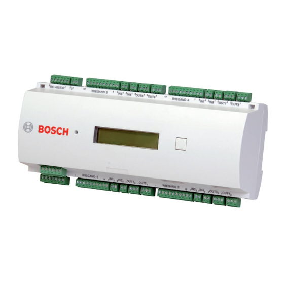
The built in compact flash adapter provides adequate storage capability for cardholders and events. The AMC2-4W electronics are completely covered by a plastic housing. The liquid crystal display provides all important status information. - Page 13 RS-485 multi‑dropped, RS-232 or 10/100 Mbit/s Ethernet. It has eight analog input devices and eight relay outputs. With its analog input devices, the AMC2-4W verifies, for example, if a lock is closed or open. The relay outputs can be used to activate lock mechanisms if access is granted, or activate the burglar alarm system if an intrusion or system alert is detected.
-
Page 14: Equipment Configuration
8 years. Spare part: VARTA CR 2032 PCB. Reset push button - reachable through the casing using a screwdriver Liquid Crystal Display Push button, available on top of the housing, to select different display modes 2016-11 | AMC2-4W | Bosch Sicherheitssysteme... - Page 15 12 Configurable 10/100 Mbit/s Ethernet host interface Figure 3.4: Overview - Interfaces 13 RS-485 extension module bus 14 External tamper contact 15 Connector for power supply 16 Wiegand interfaces for up to 4 card readers Bosch Sicherheitssysteme 2016-11 | AMC2-4W |...
-
Page 16: Performance Characteristics
Intelligent access manager for 1 - 4 entrances (for example doors, man traps, barriers) – Host address selectable using DIL sliding switch. – Four possible configurable host interfaces: – Ethernet (= standard) – RS-485 2-wire – RS-485 4-wire 2016-11 | AMC2-4W | Bosch Sicherheitssysteme... -
Page 17: System Overview
(UPS). Example: Bosch power supply APS-PSU-60 (F.01U.282.970). System Overview The Access Controller AMC2-4W is connected between the management host system and different peripheral devices. By default, a management host system is connected using Ethernet. A management host connection using RS-485 or RS-232 is also possible. - Page 18 – one AMC2 controller, – one AMC power supply, – one AMC enclosure. – The maximum configuration depends on the system software, – Each AMC2-4W controller can be extended with an AMC2-4WE extension module. 2016-11 | AMC2-4W | Bosch Sicherheitssysteme...
- Page 19 Introduction | en Controller Using Wiegand reader interfaces, up to four peripheral devices can be connected to each AMC2-4W. The interfaces are point-to- point connections, meaning that only one reader can be connected to one interface. The extension interface supports up to three additional I/O boards (AMC2-8IOE, AMC2-16IE, or AMC2-16IOE)and one AMC2-4WE.
-
Page 20: Installing
"_UL" on the delivered CD. Mounting The AMC2-4W can be attached on a standard 35 mm (1.377 in.) mounting rail using a snap-in mechanism. Attach the AMC2-4W into the upper edge of the mounting rail [1], then push down the device and snap it onto the rail by pushing it towards the back [2]. -
Page 21: Unmounting
To remove the AMC2-4W from a mounting rail, first remove all pluggable connectors. Push down the AMC2-4W until the lower edge snaps out of the mounting rail [1]. Pull the lower end of the AMC2-4W from the mounting rail [2]. -
Page 22: Opening The Case
Notice! To open the AMC2-4W, first remove all pluggable connectors. The AMC2-4W case consists of a top cover mounted with a two- point snap-in closure on a chassis. To open the case, push down the two snap-ins with a screwdriver, then swing the cover down. -
Page 23: Closing The Case
Insert the hooks on the lower edge of the front cover into the lugs on lower edge of the plastic back cover [1]. Please ensure that the BOSCH logo is not upside-down. The upper edge of the front cover now aligns with the two-point snap-in closures on the upper edge of the back cover [2], and may thus be clicked gently into place. -
Page 24: Cabling
Cabling Notice! Risk of malfunction The cables used in the AMC2-4W access control system are not prone to electrical interference. However, you should avoid routing cables close to heavy load switching cables and equipment. If this is unavoidable, cross the cable at right angles every 1 to 2 m (3 to 6 ft) to reduce interference. - Page 25 Installing | en Controller Notice! These specifications apply to power supply, readers, relay outputs, and extension interface. Regarding inputs, specific voltage-drop values need to be taken into account. Refer to Connecting Analog Input Devices, page Bosch Sicherheitssysteme 2016-11 | AMC2-4W |...
-
Page 26: Grounding And Shielding
| Installing Controller Grounding and Shielding The main grounding point at the AMC2-4W is connected to pin 2 of the power supply connector - see Connecting Diagrams, page It is good practice to shield all wires carrying low level signals. -
Page 27: Grounding For Host Interface
Figure 4.5: Location of ground jumper RS-485 host interface The jumper setting A1 shows the factory settings. Jumper JP1 connects the internal ground of the AMC2-4W to the ground of the RS-485 host interface. Jumper JP2 manages the signal ground. -
Page 28: Grounding For Extension Interface
Access Modular en | Installing Controller Notice! If the AMC2-4W is set to RS-232 mode, set jumper JP1 (= A2). 4.6.2 Grounding for Extension Interface Figure 4.6: Location of ground jumper bottom side Jumper B connects the internal ground of the AMC2-4W to the RS-485 ground of the slave interface. -
Page 29: Connecting Power Supply
– pin 4 and 7 for power good AC – pin 5 and 7 for power good Battery – pin 6 and 7 for power good DC Otherwise these pins must be short-circuited. Bosch Sicherheitssysteme 2016-11 | AMC2-4W |... -
Page 30: Ethernet Host Interface
The AMC2-4W offers a 10/100 Mbit/s Ethernet auto-sensing interface to connect to a local area network or host computer. Notice! Use either a CAT5 crossover cable to connect the AMC2-4W directly to host computer, or a standard CAT5 patch cable to connect the AMC2-4W via a network. -
Page 31: Rs-485 Host Interface
An RS-485 host system can consist of up to eight AMC2 controllers connected using 2- or 4-wire connection. Figure 4.9: Configuration of a RS-485 host system Host RS-232 connection RS-232 / RS-485 converter RS-485 bus AMC2 controller Bosch Sicherheitssysteme 2016-11 | AMC2-4W |... - Page 32 Any bus line conductor connects up to eight AMC2. Do not exceed the maximum number of devices. To use RS-485 mode at the AMC2-4W , connect the data cables to the pluggable screw connector of the RS-485 host interface. The setting of the AMC2-4W must correspond with the settings of the RS-232 / RS-485 converter.
-
Page 33: Rs-485 Two Wire Connection
Figure 4.12: Settings for RS-485 four wire connection Notice! See the notices for setting the RS-232 / RS-485 converter. Notice! If a four-wire connection is used the interface must be set up as a crosslink. Bosch Sicherheitssysteme 2016-11 | AMC2-4W |... -
Page 34: Rs-232 Host Interface
As the AMC2 controller is conceptionally a PC, it is not possible to connect them directly using normal cables. Use instead a null modem or “crossover” cable. A complete connection diagram of the RS-232 host interface is shown in chapter Connecting Diagrams, page 60 2016-11 | AMC2-4W | Bosch Sicherheitssysteme... -
Page 35: Dil Switch Selector
If using an RS-232 connection, set the address by configuring it in the Access Control System. This is a point-to-point connection that is usually configured as address 1, so set switch 1 to ON. Figure 4.14: Location of the selector for host settings Bosch Sicherheitssysteme 2016-11 | AMC2-4W |... - Page 36 RS-485 host connection with more than one and maximum eight AMC2s per bus Notice! Changing the type of the host connection requires a reset of the AMC2 - see Resetting the Software, page 52. 2016-11 | AMC2-4W | Bosch Sicherheitssysteme...
-
Page 37: Rs-485 For Extension Modules
Installing | en Controller 4.12 RS-485 for extension modules The RS-485 Extension Module Bus expands the AMC2-4W with additional I/O modules (AMC2-8IOE, AMC2-16IE, AMC2-16IOE) and/or with the reader interface extension AMC2-4WE. Figure 4.15: Location of the RS-485 extension module bus Up to three expansion modules can be connected to provide additional in- and outputs, for example, for elevator control. -
Page 38: Wiegand Interface For Card Readers
200 mA then it will require an external power supply. The AMC2-4W provides four ports for connecting a maximum of 4 readers with Wiegand interfaces. Each interface is connected using a 10-pin pluggable screw connector (S2, S7, S14, and S19) - refer to Connecting Diagrams, page 60. -
Page 39: Connecting Relay Outputs
Wiegand reader interface . 4.14 Connecting Relay Outputs To operate locks or alarm systems, the AMC2-4W has eight form C relay outputs. The outputs will be connected to the 3-pin pluggable screw connectors S5, S6, S10, S11, S17, S18, S22, and S23 - refer to Connecting Diagrams, page 60. - Page 40 Controller Figure 4.18: Location of the relay output connectors Each relay output can operate in ‘wet’ mode, using the AMC2-4W's internal 12/24 Vdc power supply for external devices or ‘dry’ mode with potential free contacts for externally powered systems. Figure 4.19: Wet mode and dry mode of the AMC2 relay outputs...
- Page 41 – inductive loads have to be short circuited using recovery diodes, see image below. These diodes (1N4004) are supplied with every AMC2-4W package. – If you need higher voltage for special applications you can connect external relays to the outputs. Recommended,...
- Page 42 Notice! Risk of damage to equipment Do not connect externally powered devices in wet mode. This can damage the AMC2-4W. 2016-11 | AMC2-4W | Bosch Sicherheitssysteme...
- Page 43 (D 1) or wet (D 2) mode. Figure 4.21: Location of relay output jumpers (bottom side) Notice! The positions of the jumpers 1 and 2 are interchanged related to the corresponding interfaces. Bosch Sicherheitssysteme 2016-11 | AMC2-4W |...
-
Page 44: Connecting Analog Input Devices
Controller 4.15 Connecting Analog Input Devices The AMC2-4W has 8 analog inputs, for example, for potential- free lock mechanisms, or to detect whether a lock is closed or open. The inputs will be connected to the 2-pin pluggable screw connectors: S3, S4, S8, S9, S15, S16, S20 and S21 - refer to Connecting Diagrams, page 60. - Page 45 To detect the four states, the voltage drop in the connecting cable may not exceed special values. The following table shows the maximum values of permissible cable resistance depending on the used resistor combination. Bosch Sicherheitssysteme 2016-11 | AMC2-4W |...
- Page 46 1700 1800 1900 Table 4.2: Maximum values of cable resistance per used resistor combination in Ohm Notice! We recommend using serial resistors (R ) no higher than 5K6 in order to obtain clear measurements. 2016-11 | AMC2-4W | Bosch Sicherheitssysteme...
-
Page 47: Tamper Protection
Installing | en Controller 4.16 Tamper Protection To protect the AMC2-4W against unauthorized access and so prevent tampering with sensitive data, the AMC2-4W provides an additional interface to connect external tamper contacts. This interface is a potential-free 2-pin pluggable screw connector marked with T. -
Page 48: Operating
Operating Status Display of the AMC2 The liquid crystal display delivers status information about the AMC2-4W. Push the 'Dialog' button to switch between different modes. Figure 5.1: Location of the ’Dialog’ button The selected display mode remains set until the next time the button is pressed. - Page 49 - output signals with an extension below. The first eight signs show the signals of the AMC2-4W and the second eight the signals of the AMC2-4WE if connected. Dig. I1: :::::::::::::::: If there are I/O-Boards connected the signals will be Dig.
- Page 50 Host: + "C" Host activity: + = online - = offline "C" = Counter of the received data packages from the host interface. RS 485 Bus connection: A = Address 1 … H = Address 8 2016-11 | AMC2-4W | Bosch Sicherheitssysteme...
-
Page 51: Configuring The Ethernet Interface
Access Modular Operating | en Controller Configuring the Ethernet Interface To configure the AMC2-4W in a TCP/IP network environment, use the AmcIpConfig tool provided in the following directory on the standalone or the remote server of the Building Integration System:... -
Page 52: Troubleshooting
The AMC2-4W deletes its application program leaving only its bootloader and network setting. As soon as it is online again, the AMC2-4W bootloader will download a fresh copy of the application program and configuration. If the problem persists please request technical support. - Page 53 Access Modular Operating | en Controller Figure 5.2: Resetting the AMC2 Bosch Sicherheitssysteme 2016-11 | AMC2-4W |...
-
Page 54: Resetting The Device To Factory Default
5.3.2 Resetting the Device to Factory Default Reset the AMC2-4W as described above. Open the upper case of the AMC2-4W as described in Opening the Case, page 22. Set all six DIL switches of the RS-485 selector to ON as shown in the figure below. -
Page 55: Technical Data
1,5 A @ 24 Vdc – Eight analog inputs with tamper detection; only connect dry contacts – RS-485 extension interface: Transfer rate: 9,6 kBit/s, no parity, 8 bit, 2 stop bit – Tamper contact for external enclosures Bosch Sicherheitssysteme 2016-11 | AMC2-4W |... - Page 56 0° C to 50°C (32° F to 122°F) Humidity Up to 95%, without condensation Housing material ABS with OC (UL 94 V-0) Dimensions (W/H/D) 232 x 90 x 63mm (8.9 x 3.5 x 2.5 in) Weight approx. 0.53kg (1.2lb) 2016-11 | AMC2-4W | Bosch Sicherheitssysteme...
- Page 57 Access Modular Technical Data | en Controller Notice! The voltage drop from the power supply to the AMC2-4W affects the AMC interfaces. The total drop must not exceed 2V! Notice! To determine the environmental impact of an installation, take into account the most extreme values of all participating devices.
- Page 58 Access Modular en | Technical Data Controller 2016-11 | AMC2-4W | Bosch Sicherheitssysteme...
- Page 59 Access Modular Technical Data | en Controller Bosch Sicherheitssysteme 2016-11 | AMC2-4W |...
-
Page 60: Appendices
Figure 7.1: Connectors on upper PCB Shield Data RxTx+ (2-wire) Data Rx+ (4-wire) Data RxTx- (2-wire) Data Rx- (4-wire) Ground (PAG) Data Tx+ (4-wire) Data Tx- (4-wire) Table 7.1: RS-485 host on upper PCB 2016-11 | AMC2-4W | Bosch Sicherheitssysteme... - Page 61 Access Modular Appendices | en Controller TXD+ TXD- RXD+ not connected not connected RXD- not connected not connected Table 7.2: Ethernet Network socket (RJ45) Figure 7.2: Interconnect diagram of the RS-232 serial interface Bosch Sicherheitssysteme 2016-11 | AMC2-4W |...
- Page 62 Access Modular en | Appendices Controller Figure 7.3: Connector blocks of the AMC2-4W 2016-11 | AMC2-4W | Bosch Sicherheitssysteme...
- Page 63 Data 0 white Data 1 drain Shield orange green LED brown red LED yellow Beeper blue Hold violet Card Present Table 7.4: Wiegand interface AMC Notice! For reader settings refer to the respective reader manual. Bosch Sicherheitssysteme 2016-11 | AMC2-4W |...
- Page 64 Power supply for external devices (10V - 30V) Power supply for external devices (0V) Shield Data RxTx+ Data RxTx- Ground (PAG) Table 7.7: Host / Extension interface Tamper Contact, in Tamper Contact, out Table 7.8: External tamper contact 2016-11 | AMC2-4W | Bosch Sicherheitssysteme...
- Page 65 Access Modular Appendices | en Controller Bosch Sicherheitssysteme 2016-11 | AMC2-4W |...
- Page 66 Access Modular en | Appendices Controller 2016-11 | AMC2-4W | Bosch Sicherheitssysteme...
-
Page 67: Index
17 inputs, 17, 44 interfaces Ethernet, 51 tamper, 47 extension, 28, 55 transfer rates, 17, 55 host, 16, 30, 31, 34, 55 reader, 17, 38, 55 unmounting, 21 interfades extension, 37 LCD, 48 Bosch Sicherheitssysteme 2016-11 | AMC2-4W |... - Page 70 Bosch Sicherheitssysteme GmbH Robert-Bosch-Ring 5 85630 Grasbrunn Germany www.boschsecurity.com © Bosch Sicherheitssysteme GmbH, 2016...