Honeywell RTHL3550 Owner's Manual
Non-programmable
Hide thumbs
Also See for RTHL3550:
- Quick installation manual (65 pages) ,
- Quick installation manual (64 pages) ,
- Operating manual (40 pages)
Table of Contents
Advertisement
Available languages
Available languages
Non-Programmable
Digital Thermostat
Owner's Manual
Read and save these
instructions.
For help please visit
yourhome.honeywell.com
Installation is Easy
1. Label wires and remove your old thermostat
2. Install and wire your new thermostat
3. Set your new thermostat to match your heating/cooling system
It is preset for the most common system
•
RTHL3550
Do you need assistance? We are here to help.
Call 1-800-468-1502 for wiring assistance before returning
the thermostat to the store.
This thermostat works on 24 volt or 750 mV systems. It
will NOT work on 120/240 Volt systems.
Advertisement
Table of Contents

Related Manuals for Honeywell RTHL3550


Summary of Contents for Honeywell RTHL3550
- Page 1 Non-Programmable RTHL3550 Digital Thermostat Owner’s Manual Read and save these instructions. For help please visit yourhome.honeywell.com Installation is Easy 1. Label wires and remove your old thermostat 2. Install and wire your new thermostat 3. Set your new thermostat to match your heating/cooling system It is preset for the most common system •...
-
Page 2: Customer Assistance
50°F (10°C). Customer assistance For assistance with this product, please visit http://yourhome.honeywell.com. Or call Honeywell Customer Care toll-free at 1-800-468-1502. To save time, please note your model number and date code before calling. - Page 3 Table of contents Installation Appendices Troubleshooting ........15 Installation ..........3 Limited warranty .........16 Advanced Installation ......10 About your new thermostat Controls and Home screen quick reference ........12 Compressor protection .......14 Replace batteries .......14 1 Turn Off Power to Heating/Cooling System Circuit breaker Heating/cooling system M31535 power switch...
- Page 4 3 Label Wires with Tags Label the wires using the supplied wire labels as you disconnect them. Wire Labels MCR31537 Terminal designation M28100 4 Separate Wallplate from New Thermostat Remove wallplate from the new thermostat and mount onto wall. M28343 Wallplate...
-
Page 5: Mount Wallplate
5 Mount Wallplate Mount the new wallplate using the included screws and anchors. M28345 Drill 3/16-in. holes for drywall Drill 3/32-in. holes for plaster 6 Connect Wires Simply match wire labels. If labels do not match letters on the thermostat, check “Alternate Wiring (Conventional Systems)”... - Page 6 Alternate Wiring (Conventional Systems) If labels do not match terminals, connect wires as shown here (see notes, below). MCR31274B If wires will be connected to both R and Rc terminals, remove metal jumper. Do not use C, X or B. Wrap bare end of wire with electrical tape. Wiring—Heat Pump If E and Aux do not each have a wire connected, use a small piece of wire to connect them to each other.
- Page 7 Alternate Wiring (Heat Pump Only) If labels do not match letters on the thermostat, check the chart below and connect to terminal as shown here (see notes, below). MCR31275B Leave metal jumper in place, connecting R and Rc terminals. If your old thermostat had both V and VR wires, stop now and contact a qualified contractor for help.
-
Page 8: Install Batteries
7 Install Batteries Install two AA alkaline batteries. M28346 Back of thermostat 8 Install Thermostat onto Wallplate Install thermostat onto the wallplate on the wall. MCR32613 9 Turn Power Back On Turn the power back on to the heating/cooling system. Circuit breaker box Heating/cooling system M31544... - Page 9 10 If your system type is... If your system type is: q Single Stage Heat and Cool Congratulations, you’re done! If your system type is: q Multistage Heat and Cool q Heat Pump* without Backup Heat q Heat Pump* with Backup Heat q Heat Only q Cool Only Continue with Advanced Installation to match your thermostat to your system...
-
Page 10: Advanced Installation
Advanced Installation Enter System Setup To enter system setup, press and hold and FAN buttons until the both the display changes (approximately 5 seconds). MCR33377 Changing Settings 1. Press the button to change Function Setting the setting. 2. Press NEXT to advance to the next function. -
Page 11: About Your New Thermostat
(10.5 to 37°C) temperature setting About your new thermostat Your new Honeywell thermostat has been designed to give you many years of reliable service and easy-to-use, push-button climate control. Large, clear, backlit display is easy to read — even in the dark. -
Page 12: Thermostat Controls
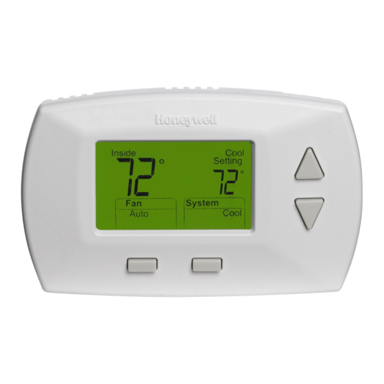
Thermostat controls Digital display Battery holder Temperature buttons Press to adjust temperature settings. MCR32585 Function buttons Press to select the function displayed just above each button. (Functions change depending on the task.) Display screen Current inside temperature Temperature setting Inside Heat Replace Battery... -
Page 13: Auto Changeover
Adjust the temperature Inside Cool Setting Press to adjust the temperature. Cool NOTE: Make sure the thermostat System is set to the system you want to Cool Auto control (heat or cool). MCR32593 Auto Changeover Use this feature in climates where both air conditioning and heating are used on the same day. -
Page 14: Compressor Protection
Built-in compressor protection This feature helps prevent damage to Inside Cool the compressor in your air conditioning Setting or heat pump system. Damage can occur if the compressor is Cool On restarted too soon after shutdown. This System feature forces the compressor to wait a Cool Auto few minutes before restarting. -
Page 15: Troubleshooting
• Check Function 1: System Type to make sure it is set to match your heating Heating system is running in cool and cooling equipment mode For assistance with this product, please visit http://yourhome.honeywell.com or call Honeywell Customer Care toll-free at 1-800-468-1502. -
Page 16: Limited Warranty
This warranty does not cover removal or reinstallation costs. This warranty shall not apply if it is shown by Honeywell that the defect or malfunction was caused by damage which occurred while the product was in the possession of a consumer. - Page 17 Termostato digital RTHL3550 no programable Manual del propietario Lea y guarde estas instrucciones. Para obtener ayuda, visite yourhome.honeywell.com La instalación es fácil 1. Rotule los cabes y retire el termostato viejo 2. Instale y conecte los cables de su nuevo termostato 3.
- Page 18 50 °F (10 °C). Services à la clientèle Para obtener asistencia relacionada con este producto, visite http://yourhome.honeywell.com. O comuníquese con el número gratuito del servicio de atención al cliente, llamando al 1-800-468-1502. Para ahorrar tiempo, anote el número de modelo y el código de fecha antes de llamar.
- Page 19 Acerca Instalación Apéndices Localización y solución Instalación ..........3 de problemas ........14 Guía de instalación avanzada ....9 Garantía limitada ........16 Acerca de su nuevo termostato Referencia rápida de los controles y la pantalla de inicio ......11 Protección del compresor ....13 Reemplazo de la batería ....14 1 Desconecte la alimentación en el sistema de calefacción/refrigeración Caja de interruptores...
- Page 20 3 Identifique los cables Identifique los cables a medida que los desconecta, utilizando las etiquetas que se suministran. Rótulos para los cables MCR31537 Designación de los terminales M28100 4 Separe la placa de montaje del termostato nuevo Retire la placa de montaje del termostato nuevo y móntela en la pared. M28343 Placa de montaje...
- Page 21 5 Coloque la placa de montaje Monte la nueva placa de montaje utilizando los tornillos y anclajes que se suministran. M28345 Taladre agujeros de 3/32 in. (2,4 mm) en yeso Taladre agujeros de 3/16 in. (4,8 mm) en paneles de yeso 6 Conecte los cables Simplemente haga corresponder las etiquetas de los cables.
- Page 22 Cableado alternativo (sistemas convencionales) Conecte MSCR31274B En caso de conectar los cables tanto al terminal R como al Rc quite el puente metálico. No use los cables C, X ni B. Coloque cinta aisladora en los extremos desnudos del cable. Cableado—bomba de calor Si E y Aux no tienen un cable conectado cada uno, utilice una pequeña pieza de cable para conectarlos uno con otro.
- Page 23 Cableado alternativo (para bombas de calor únicamente) Si las etiquetas no coinciden con las letras del termostato, controle el cuadro de la derecha y conecte el terminal como se ilustra aquí (ver notas más abajo). Conecte MSCR31275A Deje el empalme en lugar, entre terminales de R y Rc. Si su termóstato existente tenía cables V y VR ahora pare y entre en contacto con un contratista para la ayuda.
- Page 24 7 Instale las baterías Instale dos baterías alcalinas AA en la parte de atrás del termostato. M28346 Parte de atrás del termostato 8 Instale el termostato en la placa de montaje Instale el termostato en la placa de montaje en la pared. 9 Active nuevamente el MCR32613 suministro eléctrico...
- Page 25 10 Si su tipo de sistema es... Si su tipo de sistema es: q Calor y frío de una sola etapa ¡Felicitaciones, ya está listo! Si su tipo de sistema es: q Calefacción y refrigeración de etapas múltiples q Bomba de calor* sin calor de respaldo q Bomba de calor* con calor de respaldo q Calefacción únicamente q Refrigeración únicamente...
- Page 26 Descripción Presione el botón Función s o t para Configuración seleccionar el tipo de sistema de 0 Calefacción y refrigeración: Sistema de calefacción a gas, a aceite o su hogar eléctrico con aire acondicionado 1 Bomba de calor: El compresor externo proporciona tanto calefacción como refrigeración sin calefacción de respaldo o auxiliar.
-
Page 27: Acerca De Su Nuevo Termostato
Descripción Presione el botón Función s o t para Configuración seleccionar el cambio manual o 0 Cambio manual: (Calefacción/Apagado/Enfriamiento) automático 1 Cambio automático: (Calefacción/Apagado/Enfriamiento/Automático) Activa automáticamente la calefacción o el enfriamiento basado en las temperaturas de la habitación. PRECAUCIÓN: Para evitar posibles daños al compresor, no utilice la Conversión Automática si la temperatura externa es inferior a 50 ºF (10 ºC). - Page 28 Pantalla digital Temperatura interior actual Configuración de temperatura Inside Heat Replace Battery Estado del sistema Indica que el sistema Heat On está encendido. System (Cool On or Heat On.) Configuración del Auto Heat Configuración del ventilador Presione el botón FAN para sistema seleccionar Auto o On.
- Page 29 Conversión automática Utilice esta característica en climas donde se utilicen tanto el aire acondicionado como la calefacción durante el mismo día. Cuando el sistema está configurado en Auto (automático), el termostato elige automáticamente cuándo calentar o enfriar, dependiendo de la temperatura interior. Mientras está...
- Page 30 Reemplazo de la batería Instale las baterías nuevas Presione el soporte y tire inmediatamente cuando la advertencia de él para quitar. REPLACE BATTERY (reemplazo de baterías) comience a titilar. La advertencia titilará durante alrededor de Replace Battery dos meses antes de que se consuman las baterías.
- Page 31 • Controle la función 1 (Tipo de sistema) para asegurarse de que coincida con el equipo de calefacción y refrigeración calefacción está funcionando en el modo de frío Para obtener asistencia relacionada con este producto, visite http://yourhome.honeywell.com o comuníquese con el número gratuito de Atención al cliente de Honeywell 1-800-468-1502.
- Page 32 Garantía limitada de 1 año Honeywell garantiza este producto, a excepción de la batería, por el término de un (1) año contra cualquier defecto de fabricación o de los materiales, a partir de la fecha de compra por parte del consumidor. Si en cualquier momento durante el período de garantía se verifica que el producto tiene un defecto o que funciona mal, Honeywell lo...