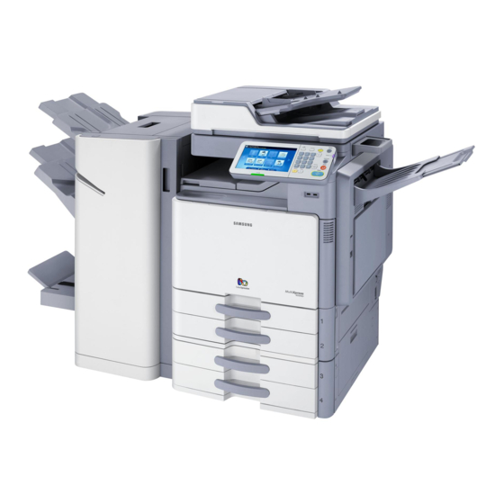
Samsung CLX-9350ND Service Manual
Digital color laser mfp
Hide thumbs
Also See for CLX-9350ND:
- Installation manual (69 pages) ,
- Brochure & specs (8 pages) ,
- Service manual (481 pages)
Table of Contents
Advertisement
Quick Links
■ Print/Copy speed
- CLX-9250ND : 25/25 ppm (A4)
- CLX-9350ND : 35/35 ppm (A4)
■ 1Ghz CPU (9350) / 800Mhz (9250)
■ 250 GB HDD
■ 1GB Memory (Max. 2GB)
Service Manual
Digital Color Laser MFP
CLX-9250ND / 9350ND
■ 8.9 inch color graphic touch-screen LCD
■ Various option units
- 3K Booklet finisher / 1K Standard finisher
DCF, HCF, Punch unit , Multi fax etc.
Advertisement
Table of Contents

Related Manuals for Samsung CLX-9350ND


Summary of Contents for Samsung CLX-9350ND
-
Page 1: Service Manual
■ Print/Copy speed ■ 8.9 inch color graphic touch-screen LCD - CLX-9250ND : 25/25 ppm (A4) - CLX-9350ND : 35/35 ppm (A4) ■ Various option units - 3K Booklet finisher / 1K Standard finisher ■ 1Ghz CPU (9350) / 800Mhz (9250) DCF, HCF, Punch unit , Multi fax etc. - Page 2 ⓒ Samsung Electronics Co.,Ltd. July. 2011 Printed in Korea. VERSION NO. : 1.9 CODE : 9x50-00000E...
- Page 3 Contents chapter 1 Precautions 1.1 Safety Warning …………………………………………………… 1-1 1.2 Caution for safety ………………………………………………… 1-2 1.3 ESD Precautions ………………………………………………… 1-5 chapter 2 Product description 2.1 Specifi cations …………………………………………………… 2-1 2.2 System confi guration …………………………………………… 2-8 2.2 Paper path ……………………………………………………… 2-9 2.3 Sensor location ……………………………………………………...
- Page 4 Contents 2.7.3 Laser synchronizing detectors …………………………… 2-45 2.7.4 Automatic line position adjustment ………………………… 2-46 2.7.5 Shutter mechanism ………………………………………… 2-49 2.8 Printer Drive system ……………………………………………… 2-50 2.8.1 Drive Motors ………………………………………………… 2-50 2.8.2 Main drive unit (OPC, DEVE, ITB, T1 DIS/ENG) ………… 2-52 2.8.3 Pick-up Drive …………………………………………………...
- Page 5 Contents 2.11.15 Cassette Joint PBA ……………………………………… 2-102 2.11.16 Side Joint PBA …………………………………………… 2-102 2.11.17 Fuser PBA ………………………………………………… 2-103 2.11.18 Waste Sensor PBA ……………………………………… 2-103 2.11.19 LED Panel PBA …………………………………………… 2-103 2.11.20 CRUM PBA ……………………………………………… 2-104 2.11.21 Development Crum Interface PBA ……………………… 2-104 2.11.22 Deve Crum Joint PBA ……………………………………...
- Page 6 Contents 3.4 Scan unit ………………………………………………………… 3-14 3.4.1 Scan glass …………………………………………………… 3-15 3.4.2 Scan main PBA ……………………………………………… 3-16 3.4.3 Lamp ………………………………………………………… 3-17 3.4.4 Original size detection sensor ……………………………… 3-19 3.4.5 Joint PBA …………………………………………………… 3-19 3.4.6 Joint sub PBA ……………………………………………… 3-20 3.4.7 Fan …………………………………………………………… 3-20 3.4.8 Pulley-belt ……………………………………………………...
- Page 7 Contents 3.7.8 DC power board …………………………………………… 3-62 3.7.9 HVPS board ………………………………………………… 3-63 3.7.10 Lift motor …………………………………………………… 3-66 3.7.11 SMPS board ………………………………………………… 3-66 3.7.12 SMPS FAN ………………………………………………… 3-67 3.7.13 Ozone Filter FAN ………………………………………… 3-69 3.7.14 Side joint board …………………………………………… 3-70 3.8 Main drive unit …………………………………………………… 3-71 3.8.1 Main drive PBA ………………………………………………...
- Page 8 Contents 3.13.3.3 Face Up Exit Lower ………………………………… 3-109 3.13.3.4 Solenoid ……………………………………………… 3-110 3.13.4 Exit unit …………………………………………………… 3-111 3.14 Laser Scanning Unit …………………………………………… 3-114 3.15 Cassette heating cable ……………………………………… 3-119 chapter 4 Service mode (Diagnostic mode) 4.1 Entering/Exiting Diagnostics Mode ……………………………… 4-1 4.2 Serive mode menu tree ……………………………………………...
- Page 9 Contents 4.5.3.2 Scanner/DADF NVM Read/Write …………………… 4-27 4.5.3.3 Scanner/DADF Test Routines ……………………… 4-28 4.5.4 Adjustment ………………………………………………… 4-30 4.5.4.1 Print Adjustment ……………………………………… 4-30 4.5.4.2 Copy Adjustment ……………………………………… 4-32 4.5.4.3 Scan Area Adjustment ………………………………… 4-33 4.5.4.4 DADF Adjustment ……………………………………… 4-35 4.5.4.5 Finisher Adjustment …………………………………… 4-37 4.5.5 ACS(Auto Color Sensing) …………………………………...
- Page 10 Contents 6.2.2 Imaging unit ………………………………………………… 6-7 6.2.3 Cartridge Transfer Unit …………………………………… 6-12 6.2.4 2nd Transfer roller ………………………………………… 6-15 6.2.5 Fuser Unit …………………………………………………… 6-16 6.2.6 Pick up/ Retard/ Forward roller …………………………… 6-17 6.2.7 Ozone Filter ………………………………………………… 6-17 6.2.8 Dust Filters ………………………………………………… 6-18 6.2.9 DADF Rollers (Pick up /ADF/ Retard) ……………………...
- Page 11 Contents 7.3.7 Uneven pitch and jitter image ……………………………… 7-145 7.3.8 Skewed image ……………………………………………… 7-146 7.3.9 Low image density ………………………………………… 7-147 7.3.10 Blank copy, Black copys ………………………………… 7-154 7.3.11 Uneven density in sub scan direction …………………… 7-156 7.3.12 Uneven density in main scan direction ………………… 7-157 7.3.13 Gradation reproduction failure ……………………………...
- Page 12 Contents 9.5 Error Page ………………………………………………………… 9-6 9.6 Progress Page …………………………………………………… 9-7 9.7 Error List …………………………………………………………… 9-8 9.8 HDD Repair ……………………………………………………… 9-8 9.9 HDD Failure ……………………………………………………… 9-10 Reference information chapter 10 10.1 Tools for troubleshooting ……………………………………… 10-1 10.2 Abbreviations …………………………………………………… 10-4...
-
Page 13: Safety Warning
High voltages and lasers inside this product are da ngerous. This printer should only be serviced by a qualified service technician. (2) Use only Samsung replacement parts (2) Use only Samsung replacement parts. There are no user serviceable parts inside the print ter. -
Page 14: Caution For Safety
(12) Do not insert any metal objects into the machine th hrough the ventilator fan or other part of the casing, it could make contact with a high voltage conductor inside the machine and cause an electric shock. Service Manual SAMSUNG ELECTRONICS CLX-9250/9350 series... -
Page 15: Handling Precautions
OPC-ACR surely. 1.2.4 Assembly / Disassembly Precau utions Replace parts carefully and always use Samsung part ts. Take care to note the exact location of parts and cable routing before dismantling any part of the machi ne. - Page 16 -If you are moving the machine a long distance, you sh hould remove toner & imaging unit, lock scan carrier & staple unit, tape and disassemble all trays. (e.g : m moved by truck or so) Service Manual SAMSUNG ELECTRONICS CLX-9250/9350 series...
-
Page 17: Esd Precautions
ESDs. Normal motions, such as the brushing together of clothing fabric and lifting on ne’s foot from a carpeted floor, can generate static electricity sufficient to damage an ESD electricity sufficient to damage an ESD. Service Manual SAMSUNG ELECTRONICS CLX-9250/9350 series... -
Page 18: Product Description
Note - See the Rating label on th he machine for correct voltage, frequency (hertz) and type heating wire in of current. DCF/HCF The voltage rating of heating wire e is the same as the machine’s voltage rating. Service Manual SAMSUNG ELECTRONICS CLX-9250/9350 series... -
Page 19: Printer Specifications
• Color: 8.5 seconds (from ready) Copy resolution • Platen : 600 x 600 dpi • Document feeder: Up to 600 x 6 600 dpi • Platen : 25% to 400% Zoom range • Document feeder: 25% to 400% Service Manual SAMSUNG ELECTRONICS CLX-9250/9350 series... -
Page 20: Scanner Specifications
• Fine : 203 x 196 6 dpi Resolution • Super Fine : 30 0 x 300 dpi • Ultra Fine : 600 x 600 dpi Memory HDD Backup Auto dialer up to 500 numbe Service Manual SAMSUNG ELECTRONICS CLX-9250/9350 series... - Page 21 Pick up roller CLX-PMK11C Retard roller 225,000 Tray 1,2,3,4, HCF Forward roller Pick up roller CLX-PMK12C ADF roller 225,000 DADF Retard roller MP Pick up roller CLX-PMK13C MP Retard roller 150,000 MP Tray MP Forward roller Service Manual SAMSUNG ELECTRONICS CLX-9250/9350 series...
-
Page 22: Paper Specifications
Kit components Remark OPE DUMMY FRONT VAL-K016DE/ELS Quick Install Guide GERMANY Quick Reference Guide OPE DUMMY FRONT VAL-K016IT/ELS VAL K016IT/ELS Quick Install Guide Quick Install Guide ITALY ITALY Quick Reference Guide VAL-PC20UK/XEU POWER CORD Service Manual SAMSUNG ELECTRONICS CLX-9250/9350 series... - Page 23 Heating Wire is the same as the machine’s voltage rating) Heating wire for Scan 220V V, 5W and 10W (equipped by service person at field, voltage CLX-DHK12S ratin ng of Heating Wire is the same as the machine’s voltage rating) Service Manual SAMSUNG ELECTRONICS CLX-9250/9350 series...
- Page 24 Main unit Fax multi-line kit Optional tray High capacity feeder Fax kit (CLX-FAX250) (CLX-PFP000) (CLX-HCF102) (CLX-FAX150) (CLX-D DSK10T) Expansion memory module 1G D I kit (CLX-MEM300) (CLX X-KIT10F) Cassette / Scanner Heating cable (CLX-DHK11C/12C/11S/12S) (CLX-DHK11C/12C/11S/12S) Service Manual SAMSUNG ELECTRONICS CLX-9250/9350 series...
-
Page 25: System Configuration
DADF width guides (tray1, tray2) DADF input tray Front door DADF output tray Front door handle Face-up tray* Control panel Standard tray right bottom door Face-Down tray Optional dual cassette feeder right bottom door bottom door Service Manual SAMSUNG ELECTRONICS CLX-9250/9350 series... -
Page 26: Front View 2
2. Product d description Front view 2 Scanner glass Power-switch Sponge-sheet Power receptacle Multi-purpose tray USB port (2 EA) Multi-purpose tray paper width guide Service Manual SAMSUNG ELECTRONICS CLX-9250/9350 series... -
Page 27: Rear View
2. Product d description Rear view Optional dual cassette feeder cable USB host port DADF cable Finisher connector Scanner locking screw Network port USB port (Connection port to computer) (Connection port to computer) Service Manual SAMSUNG ELECTRONICS CLX-9250/9350 series... -
Page 28: Inner View
2. Product d description Inner view Waste toner container Imaging units Toner cartridge Inner cover Service Manual SAMSUNG ELECTRONICS CLX-9250/9350 series... - Page 29 2. Product d description View with standard finisher (option Standard finisher front door Top tray Manual stapler Top door Manual stapler button Standard finisher Front door handle Finishing tray Staple Service Manual SAMSUNG ELECTRONICS CLX-9250/9350 series...
- Page 30 2. Product d description View with booklet finisher1 (optiona Booklet tray Manual stapler button Finishing tray Finishing tray Top tray Top tray Booklet finisher front door Top door Manual stapler Booklet finisher front door handle Service Manual SAMSUNG ELECTRONICS CLX-9250/9350 series...
- Page 31 2. Product d description View with booklet finisher2 (optiona Knife wheel Staple Booklet maker handle Booklet Staple (2 EA) Fold wheel Booklet maker cover Booklet jam removal wheel Service Manual SAMSUNG ELECTRONICS CLX-9250/9350 series...
- Page 32 Optiona al tray Flatbed scanner (Stand / / HCF / DCF) Image Transfer Belt Pick up / Retard / Document output tray Forward d rollers (ITB) unit Imaging units MP tray Document input tray Service Manual SAMSUNG ELECTRONICS CLX-9250/9350 series...
-
Page 33: Paper Path
2. Product d description Paper Path The following diagram displays the path the paper follo ows during the printing process. DADF path Face up exit Finisher path Simplex Duplex path path Service Manual SAMSUNG ELECTRONICS CLX-9250/9350 series... -
Page 34: Sensor Location
JC92 02160 JC92-02160 SENSOR-HUMIDITY JC32-00005 A3-3211 / A3-3212 PBA SENSOR ACR JC32-00012 S2-3114 / S2-3115 PBA-ENGINE PBA SENSOR ACR JC32-00012 S2-3114 / S2-3115 CLX-9350ND SWITCH FRONT COVER JC32-00012 S2-4210 : JC92-02129A PHOTO INTERRUPTER PHOTO-INTERRUPTER 0604 00139 0604-00139 CLX-9250ND PHOTO-INTERRUPTER 0604-00139... - Page 35 2. Product d description Part Ref. Description Controller PCB Relative Error Code Number PBA-ENGINE SENSOR-PAPER SIZE JC32-00013 M1-4211 CLX-9350ND : JC92-02129A : JC92 02129A SENSOR-HUMIDITY JC32-00005 A3-3311 / A3-3312 CLX-9250ND : JC92-02239A PBA-COVER OPEN SENSOR JC92-02143 U3-4210 PBA-SCAN JOINT (JC92-02144A)
- Page 36 Part Ref. Description Controller PCB Relative Error Code Number PHOTO-INTERRUPTER 0604-00139 M3-2220 PHOTO-INTERRUPTER 0604-00139 M3-1313 PBA-ENGINE PHOTO-INTERRUPTER 0604-00139 M3-1313 CLX-9350ND PHOTO-INTERRUPTER 0604-00139 M2-1333 : JC92-02129A PHOTO-INTERRUPTER 0604-00138 M2-2215 CLX-9250ND CLX-9250ND : JC92-02239A PHOTO-INTERRUPTER 0604-00139 M2-2113 PHOTO-INTERRUPTER 0604-00139 M3-2320 Service Manual...
- Page 37 0604-00 01393 PHOTO-INTERRUPTER 0604-00 01393 PHOTO-INTERRUPTER 0604-00 01393 C5-1551 PHOTO-INTERRUPTER 0604-00 01393 M2-2251 PBA-ENGINE PHOTO-INTERRUPTER 0604-00 01399 M1-1615 CLX-9350ND PHOTO-INTERRUPTER 0604-00 01381 M2-12133 : JC92-02129A M2-2313 CLX-9250ND VR-SLIDE 2102-00 01020 : JC92-02239A PHOTO INTERRUPTER PHOTO-INTERRUPTER 0604 00 0604-00 01393 01393...
-
Page 38: Paper Handling Section
Feed sensor, Registration sensor, and Drive system for these components. The Transport motor is s used to drive all of these rollers. 2.4.1 Overview The following diagrams display the positions of the pa per path rollers. Service Manual SAMSUNG ELECTRONICS CLX-9250/9350 series... - Page 39 Tray1 paper motor Pick Up size detection Tray1 transport detection Tray2 paper empty detection Tray2 lift Tray2 transport detection motor Tray2 paper size detection Tray2 upper limit detection Tray2 pape er remaining quantity det tection Service Manual SAMSUNG ELECTRONICS CLX-9250/9350 series...
- Page 40 Detects face up tray i install CN9 @ SIDE JOINT PBA, 3PIN Tray1 Lift Motor Lifting knock up plate CN4@ Cassette Joint PBA, 3Pin Tray2 Lift Motor Lifting knock up plate CN4@ Cassette Joint PBA, 3Pin Service Manual SAMSUNG ELECTRONICS CLX-9250/9350 series...
-
Page 41: Components
Roller fuser Sensor fuser out Roller exit Roller face down exit Actuator face down bin full Sensor duplex return Sensor duplex return Roller duplex return Roller face up exit Actuator face up bin full Service Manual SAMSUNG ELECTRONICS CLX-9250/9350 series... -
Page 42: Functions
Registration Sensor This sensor detects that the leading edge of the paper r has reached the registration roller and that the trailing edge of the paper has passed the registration r roller. Service Manual SAMSUNG ELECTRONICS CLX-9250/9350 series... -
Page 43: Paper Tray
-. Special Paper : 12"×18", Label, Card stock (Label : 50 sheets, Thick Cards stock [170~216 g/㎡ : 350 sheets) • Weight : plain paper 60 ~ 216g/㎡ • Plate knock up Lift type : Lift Motor + Up Limit Senso Service Manual SAMSUNG ELECTRONICS CLX-9250/9350 series... -
Page 44: Pick Up Unit
The following is a diagram of the pickup roller: Forward Roller Retard Roller Actuator-Empty Sensor Pick Up Roller Service Manual SAMSUNG ELECTRONICS CLX-9250/9350 series... -
Page 45: Registration Unit
- Duplex Side Margin : 4 23 ± 2 0 mm ( Tray3 . Duplex Side Margin : 4.23 ± 2.0 mm ( Tray3 3 4 HCF : 4 23 ± 2 0 mm ) 3, 4, HCF : 4.23 ± 2.0 mm ) Service Manual SAMSUNG ELECTRONICS CLX-9250/9350 series... -
Page 46: Mpf Unit
3.87”×5.8” (98×148㎜) • Media weight : Plain paper 60 ~ 253g/㎡ • Feeding speed : 30 ppm (CLX-9350ND), 20 ppm (CL LX-9250ND) in Letter/A4 LEF (Long Edge Feeding) • Auto size sensing : A6 SEF, Statement SEF, B5 S... -
Page 47: Imaging Unit
OPC drums transfer toner from the drums to the transfer belt. Four toner images are super r-imposed onto the belt. b. Second transfer: The transfer roller transfer rs the toner from the transfer belt to the media. Service Manual SAMSUNG ELECTRONICS CLX-9250/9350 series... - Page 48 [C]: Line position adjustment (rear) [D]: Humidity Sensor (Internal). The ID sensor output is used for the following: - Process control and for automatic line positio - Skew correction - Color registration adjustments for the latent i mage. Service Manual SAMSUNG ELECTRONICS CLX-9250/9350 series...
- Page 49 The CRUM chip in the image unit stores the data abou ut the Imaging unit. C Drum Magnetic Roller Cleaning blade Eraser harge scorotron Mixing Auger Service Manual SAMSUNG ELECTRONICS CLX-9250/9350 series...
-
Page 50: Drum Drive
Y Drum phase e sensor M Drum phase sensor Coupling C Drum phase sensor K Drum phase sensor Drum-Y Drum-M Drum-C Drum-K Drive motor BLDC Coupling OPC Gear-Drive OPC Coupling Deve Micro Clutch BLDC motor Service Manual SAMSUNG ELECTRONICS CLX-9250/9350 series... - Page 51 [C]. The TD sensor [C] in the imaging unit is used for controlling the operating range of toner density. The im maging unit is equipped with a CRUM in which some information about the imaging unit is stored. Service Manual SAMSUNG ELECTRONICS CLX-9250/9350 series...
- Page 52 Filters [B] on the top of the development unit ensure th hat the internal pressure does not become too high. During the operating, this prevents contamination of th he imaging unit by the toner. [B] Filter [A] Auger Service Manual SAMSUNG ELECTRONICS CLX-9250/9350 series...
- Page 53 Image Transfer Ro oller (Primary transfer) ITB D i ITB Drive Roller R ll Tension Roller Rotation Encoder Cleaning EEPROM Cleaning Blade ACR Sensor Paper Transfer Ro oller Toner Collection A Auger ITB Belt EEPROM Service Manual SAMSUNG ELECTRONICS CLX-9250/9350 series...
-
Page 54: Transfer Belt Drive
If the sensor has read an unusually large number of notches or an unus sually small number of notches, the controller ignores such unusual signals. Therefore, an incorrect reading does not affect the rotation speed. Service Manual SAMSUNG ELECTRONICS CLX-9250/9350 series... - Page 55 The Film [D] on the Cleaning Unit protects against ton er contamination. The driving power from the drive roller is transferred to the tension roller [E]. The Gear [F] drives the Gear [G]. Other Side Service Manual SAMSUNG ELECTRONICS CLX-9250/9350 series...
-
Page 56: Fuser Unit
Fusing Belt Heat Roller Thermistor (0.5mm-1.0mm distance) Thermostat Fuser Ro ller Pressure Roller NC Sensor Halogen Lamp Halogen Lamp Service Manual SAMSUNG ELECTRONICS CLX-9250/9350 series... - Page 57 NC sensor malfunction. These thermostats are used to prevent abnormal operation. When the th hermostat is triggered, it must be replaced (as well as the other damaged parts in the fuser unit). Service Manual SAMSUNG ELECTRONICS CLX-9250/9350 series...
-
Page 58: Fuser Unit Drive
[E] and roller [C] . The heat roller [D] is driven by pressure with the fuser belt [E] fuser belt [E]. Exit Motor [A] Fuser Belt [E] Heat Roller [D] Pressure Roller [B] Fuser Roller [C] Service Manual SAMSUNG ELECTRONICS CLX-9250/9350 series... -
Page 59: Temperature Control
• If one of the thermostat temperatures becomes highe er than 170°C, it opens and cuts power to the fusing lamp. If the other thermostat temperature becomes h higher than 170°C, it also opens and cuts power to the fusing lamp. Service Manual SAMSUNG ELECTRONICS CLX-9250/9350 series... -
Page 60: Laser Scanning Unit
C: Scan direction Y: Scan direction LD PBA P/Mirror Motor F1 Lens K: Scan direction M: Scan direct F2 Lens Skew Adjust Assy Shutter & Shutter Drive Motor Assy Joint PBA LSU Temp PBA Service Manual SAMSUNG ELECTRONICS CLX-9250/9350 series... - Page 61 The LSU has 2 types dependin g on printing speed. The difference between the two printer models is shown in the table below: Mode CLX-9250ND(25ppm) CLX-9350ND(35ppm) Remarks Laser Diode : Single Beam Laser Diode : Dual Beam LD Unit...
- Page 62 (Hsync) signal. The following diagram shows the data scannin ng direction for each color. Black (& Magenta) and Cyan (& Yellow) use the same polygon motors scanni ng in opposite directions. Service Manual SAMSUNG ELECTRONICS CLX-9250/9350 series...
-
Page 63: Automatic Line Position Adjustment
The transfer belt-cleaning unit cleans the transfer belt after the patterns are measured. Front Center Rear KK, CC, MM, YY: Spaces betwee en two lines of the same color. KC, KM, KY: Spaces between a black line and each color line. Service Manual SAMSUNG ELECTRONICS CLX-9250/9350 series... -
Page 64: Adjustment Conditions
Line position n adjustment is automatically performed when one of these conditions occurs: ∆t (Power On) > Time threshold (default: 10 minut • tes) ∆t (Wakeup) > Time threshold (default: 18 minutes • Service Manual SAMSUNG ELECTRONICS CLX-9250/9350 series... - Page 65 F2 lens [B] respectively, t th f th F2 l based on the F2 lens position for black. This th F2 l k Thi mechanism corrects main scan skew. [C/M/Y] Service Manual SAMSUNG ELECTRONICS CLX-9250/9350 series...
-
Page 66: Shutter Mechanism
When the shutter is not on at printing, the “LSU Unit Failure #U2-5113: Tur rn off then on” error message will display. [ Shutter open ] [ Shutter closed ] Service Manual SAMSUNG ELECTRONICS CLX-9250/9350 series... -
Page 67: Printer Drive System
Related Related ITEM Type Function error Duplex Return HB-STEP Return driving at Duplex BLDC Fuser / Exit driving A1-1213 Fuser / Exit E-CLT Exit driving control A1-6110 PM-STEP Fuser pressure Mode A1-6111 Service Manual SAMSUNG ELECTRONICS CLX-9250/9350 series... - Page 68 DEVE control C : A1-2412 K : A1-2512 BLDC T1 Dis/En PM-STEP T1 Dis/Engage A1-4111 LSU Shutter PM-STEP LSU shutter driving U2-6111 Waste Toner Waste Toner Container PM-STEP Container leveling T2 Dis/Eng T2 Dis/Engage Service Manual SAMSUNG ELECTRONICS CLX-9250/9350 series...
-
Page 69: Front View
T1 HV ITB Coupling Coupling OPC Coupling MagR HV Grid HV Scoro otron HV Imaging unit Connector Deve (Auger) Coupling Information SEC-CODE : JC93-00044A P t N Part Name : DRIVE-MAIN DRIVE MAIN Service Manual SAMSUNG ELECTRONICS CLX-9250/9350 series... -
Page 70: Pick-Up Drive
2 tray by e-clutch H-Step H-Step Pulley Gear Pulley Gear Gear Gear Clutch Clutch Pick-up 1 driving Pick up 1 driving Belt Belt Gear Feed 1 driving Feed 2 driving Gear Gear Gear E-Clutch Pick-up 2 driving Service Manual SAMSUNG ELECTRONICS CLX-9250/9350 series... - Page 71 Duplex and MP drives : 1 H- -Step rising by E-Clutch H-Step H Step Belt Belt Pulley Gear Pulley Gear Regi driving Regi. driving E-Clutch MP driving H-Step Belt Pulley Gear Pulley Gear Pulley Gear DUP driving E-Clutch Service Manual SAMSUNG ELECTRONICS CLX-9250/9350 series...
- Page 72 Fuser driving Roll 1. BLDC FUSER A/B FUSER IDLE B FUSER IDLE A FUSER EXIT RDCN EXIT IDLE A XIT IDLE B Clutch-E Exit Roll driving 2. H-Step DUP RDCN Duplex Retu urn driving Service Manual SAMSUNG ELECTRONICS CLX-9250/9350 series...
-
Page 73: Lsu Shutter Drive
PM Step motor & Worm : WT TB Leveling driving Step (PM) Step (PM) Worm Worm GEAR WTB RDCN GEAR WTB RDCN GEAR WTB IDLE A GEAR WTB IDLE A WTB Leveling driving WTB Leveling driving Service Manual SAMSUNG ELECTRONICS CLX-9250/9350 series... -
Page 74: Toner Supply Drive
2. Product d description 2.8.8 Toner Supply Drive The following photo displays the location of the Toner Supply drive: Bottle Coupling Duct Coupling Information SEC-CODE : JC31-00124A Part Name : MOTOR GEARED-T_SUPPLY Service Manual SAMSUNG ELECTRONICS CLX-9250/9350 series... -
Page 75: Scanner System
These lines are composed with 3-line color devices an nd a black-and-white device with no filter. 7. Auto Paper Sensor Reflector 2. FR module 3. HR module 1. DADF Glass Xe-Lamp 6. Scan Main Board 5. CCD Board 4. Lens Driving Pulley Service Manual SAMSUNG ELECTRONICS CLX-9250/9350 series... - Page 76 This is a plate to efficiently direct the light from the e Xe-lamp to the surface of the Document on the glass. • • Mirror 1 Mirror-1 This mirror directs the light reflected from the Doc ument to the mirror-2 (described later). Service Manual SAMSUNG ELECTRONICS CLX-9250/9350 series...
- Page 77 This is a board to perform image correction, such as shading correction and Image Enhancement. 7. Auto Paper Sensor The size of an original placed on the glass is instantly y detected using the Auto Paper Sensor fixed on the Align-frame. Service Manual SAMSUNG ELECTRONICS CLX-9250/9350 series...
-
Page 78: Dadf System
Feed out roller Ejects a sca anned original. Duplex registration roller Aligns pape er and transfers it to the paper path in duplex mode. Feed in roller Feeds an o riginal before scanning. Service Manual SAMSUNG ELECTRONICS CLX-9250/9350 series... -
Page 79: Electric Parts Layout
JC92-02166 PBA-ADF PHOTO-INTERRUPTER U3-3611, U3-3613 0604-00139 PBA-ADF (Exit) U3-3614 U3-3311, U3-3313, PHOTO-INTERRUPTER 0604-00138 PBA-ADF U3-3314, U3-3511, (Scan Read) U3-3513, U3-3514 PBA-WIDTH SENSOR JC92-0216 PBA-ADF PHOTO-INTERRUPTER 0604-00139 PBA-ADF PHOTO-INTERRUPTER 0604-00139 PBA-ADF PHOTO-INTERRUPTER 0604-00139 PBA-ADF U3-4210 Service Manual SAMSUNG ELECTRONICS CLX-9250/9350 series... -
Page 80: Dadf Drive System
When the direction of the original is changed during duplex mode, it transports the original to the e Regi motor. Pick up m motor drive section Regi motor drive section xit motor drive section Feed motor drive section Service Manual SAMSUNG ELECTRONICS CLX-9250/9350 series... - Page 81 3.When all originals are fed and the tray is empty, the pick-up motor rotates in reverse and the stopper moves down. The printer enters stand-by status. Pick up motor Pick up motor Pick up roller Pick up roller ADF roller ADF roller Service Manual SAMSUNG ELECTRONICS CLX-9250/9350 series...
- Page 82 Nip, the e motor rotates to align the original. The registration motor repeats rotation and stopping to align each origi inal. Regi motor PULLEY-S2M Z26 PULLEY-S2M Z48/26 PULLEY-S2M Z26 ROLLER-REGI SIM ROLLER-DU UP REGI Service Manual SAMSUNG ELECTRONICS CLX-9250/9350 series...
-
Page 83: Drive Assembly
The feed motor rotates continually during scan operation. As a result, optimum scan quality is achiev ved. Feed motor PULLEY-S2M Z48/26 PULLEY-S2M Z26 PULLEY-S2M Z26 ROLLER-FEED IN ROLLER-FEED Service Manual SAMSUNG ELECTRONICS CLX-9250/9350 series... - Page 84 The fixed feed roller rotates. The idle roller creates feeding force by using spring pressure. Exit motor PULLEY-S2M Z2 PULLEY-S2M Z48/26 EXIT PULLEY-S2M Z26 PULLEY-S2M Z26 ROLLER-EXIT ROLLER EXIT ROLLER EXIT TURN DUP ROLLER-EXIT T-TURN Service Manual SAMSUNG ELECTRONICS CLX-9250/9350 series...
- Page 85 In the on position, it opens to the direction of reverse path for 2-side scann ing. In the off position, it opens to the direction of the simplex exit section. Solenoid-R GUIDE-GATE-SIMPLEX Solenoid-F GUIDE-GATE-JUN NCTION Service Manual SAMSUNG ELECTRONICS CLX-9250/9350 series...
-
Page 86: Video Controller
Engine Contro oller. The Fax Controller (FCON) is used to control all faxing g jobs and transceiving fax data to and from the Video Controller through the PCIe high speed bus. Service Manual SAMSUNG ELECTRONICS CLX-9250/9350 series... -
Page 87: Ope Controller
The soft Power Switch in the OPE Controller left- side is used to safely shut down the system power. It i s controlled by the MICOM. Service Manual SAMSUNG ELECTRONICS CLX-9250/9350 series... -
Page 88: Engine Controller
Circuit Board Locations The following diagrams show the locations of the print er circuit boards: Engine Controller Video Controller Video Controller DC Power SMPS Toner Co nnector Deve joint HVPS2 HVPS1 Paper r tray Joint Service Manual SAMSUNG ELECTRONICS CLX-9250/9350 series... -
Page 89: Scan Controller
FLASH MSOK Device Host 256MB 32MB ISP1582 OXU210 USB HUB USB HUB USB HUB USB HUB 2514 2514 USB HOST Port Engine I/F USB HUB Scanner Controller Controller [ Video Cont roller diagram ] Service Manual SAMSUNG ELECTRONICS CLX-9250/9350 series... - Page 90 ENGINE CONTROLLER I/F CONNECTOR MSOK PBA I/F CONNECTOR HDD I/F CONNECTOR POWER CONNECTOR FDI CONNECTOR Information • SEC-CODE CLX 9350ND : JC92 02150A CLX-9350ND : JC92-02150A CLX-9250ND : JC92-02235A • PBA Name : PBA-MAIN Service Manual SAMSUNG ELECTRONICS CLX-9250/9350 series...
- Page 91 When a Video Controller PBA needs to be exchanged d, the MSOK PBA should be re-installed to the new Video Controller PBA to retain the system information Information SEC-CODE : JC92-02267A PBA Name : PBA-MSOK Service Manual SAMSUNG ELECTRONICS CLX-9250/9350 series...
- Page 92 SEC-CODE : JC92-02268A PBA Name : PBA-FAX JOINT Connection Ext. RIP PBA I/F CONNECTOR (For Future ICON PBA I/F CONNECTOR FCON PBA I/F CONNECTOR Primary MODEM CARD I/F CONNECTOR Secondary MODEM CARD I/F CONNECTO Service Manual SAMSUNG ELECTRONICS CLX-9250/9350 series...
- Page 93 C J i t PBA the Dual MODEM CARDs also connected to the Con-J Joint PBA. Information FAX-Kit model name : CLX-FAX150 SEC-CODE : JC92-02148A PBA Name : PBA-DUAL FAX CONTROL Service Manual SAMSUNG ELECTRONICS CLX-9250/9350 series...
- Page 94 Information Information FAX-Kit model name : CLX-FAX150 SEC-CODE : JC92-02141B PBA Name : PBA-FAX CARD Connection CON JOINT I/F CONNECTOR TEL LINE I/F CONNECTOR EXTERNAL PHONE I/F CONNECTOR Service Manual SAMSUNG ELECTRONICS CLX-9250/9350 series...
- Page 95 Tel line connector, no external phone connector. Information FAX-Kit model name : CLX-FAX250 SEC-CODE : JC92-02250A PBA Name : PBA-SECOND FAX CARD Connection CON JOINT I/F CONNECTOR CON JOINT I/F CONNECTOR TEL LINE I/F CONNECTOR Service Manual SAMSUNG ELECTRONICS CLX-9250/9350 series...
- Page 96 2. Product d description 2.11.1.7 Image Controller (ICON N) – CLX-9350ND Only The Image Controller (ICON) PBA is used to control a nd manipulate some scanned and stored image. The ICON PBA is comprised of a CPU (CIP6,400MHz z,PCI interface), a PCIe express Bridge chip, 256MB DDR2 Memory and 4MB Flash Memory DDR2 Memory and 4MB Flash Memory .
- Page 97 The Module interfaces to the Vide eo Controller. Information SEC-CODE : JC92-01616A PBA Name : PBA SUB-FDI Connection CONNECTOR TO VIDEO CONTROLL Service Manual SAMSUNG ELECTRONICS CLX-9250/9350 series...
- Page 98 OPE Controller & Touch Panel DDR2 MEMORY Touch Screen Processor 128MB Controller 32-bit AU1250 700MHz USB Host SUB KEY PBA for a key b’d BUZZER USB HUB Video Controller Controller Engine Controller Engine Controller Service Manual SAMSUNG ELECTRONICS CLX-9250/9350 series...
- Page 99 OPE Controller PBA Information SEC-CODE : JC92-02140A PBA Name : OPE MAIN Connection KEY PBA I/F CONNECTOR KEY PBA I/F CONNECTOR HUB PBA I/F CONNECTOR LCD I/F CONNECTOR USB HOST PORT FOR KEY BOARD Service Manual SAMSUNG ELECTRONICS CLX-9250/9350 series...
- Page 100 2. Product d description 2.11.2.1 Sub Key PBA Information SEC-CODE : JC92-02266A PBA Name : SUB KEY Connection INTERFACE CONNECTOR TO OPE M INTERFACE CONNECTOR TO OPE M MAIN MAIN Service Manual SAMSUNG ELECTRONICS CLX-9250/9350 series...
- Page 101 THE ENGINE CONTROLLER OPE MAIN PWR CONNECTOR TO O THE OPE MAIN PBA USB HOST PORT FOR INTERFAC CE EXT.DEVICES USB UPSTREAM PORT TO THE V VIDEO MAIN PBA CASSETTE Indicating LED CASSETTE Indicating LED Service Manual SAMSUNG ELECTRONICS CLX-9250/9350 series...
- Page 102 Engine SMPS Controller DDR2 S SDRAM HVPS Engine e Con. Fuser Engine CPU Control Engine e Con. ATMEGA 88 Deve/ITB Fans Fans PWMs PWMs Moto Clutc ch & BLDC/Step Sensors Solen noid Motors DCF/HCF/Finisher Service Manual SAMSUNG ELECTRONICS CLX-9250/9350 series...
- Page 103 SIDE DRAWER JTAG PAPER REGI FINISHER DRIVE POWER POWER 5V DRIVE JOINT POWER 24V SMPS I/F HVPS I/F ( 2 / 2 ) HVPS I/F ( 2 / 2 ) MSOK I/F MSOK I/F Service Manual SAMSUNG ELECTRONICS CLX-9250/9350 series...
- Page 104 OK PBA should be re-installed to the new PBA to retain the system information. Information SEC CODE : JC92 02263A SEC-CODE : JC92-02263A PBA Name : PBA-MSOK Connection Connection CONNECTOR TO ENGINE CONTRO LLER Service Manual SAMSUNG ELECTRONICS CLX-9250/9350 series...
- Page 105 Main PBA, and PCI to PCIe bridge. DDR2 CIP6 CIe- ridge Information SEC-CODE : JC92-02170A PBA Name : PBA-SCAN Connection SCAN JOINT PBA APS SENSOR APS SENSOR CCDM PBA CCDM PBA LED PANEL PBA Service Manual SAMSUNG ELECTRONICS CLX-9250/9350 series...
-
Page 106: Dadf Controller
SCAN READ SENSOR MIXED SENSOR PBA LENGTH SENSOR PBA PLATEN/EXIT MOTOR REAR SOLENOID PICKUP/REGI MOTOR SCAN JOINT PBA PICKUP CHECK/ COVER OPEN SENSOR LED PANEL PBA/ FRONT SOLENOID EXIT/ EXIT TURN SENSOR EXIT/ EXIT TURN SENSOR Service Manual SAMSUNG ELECTRONICS CLX-9250/9350 series... -
Page 107: Interface Part
The signal wir res provide electronic control signals that are used for starting and stopping the motors, operating clutches, a activating solenoids, sensing the unit state, etc. Service Manual SAMSUNG ELECTRONICS CLX-9250/9350 series... -
Page 108: Smps Board
DC 24V : 432W MPS FAN OUT MPS Control Signal1 (from Engine PBA) ser AC Output ser_AC Output UTPUT_24V1/2/3/4/5/6 (to DC POWER PBA) MPS Control Signal2 (from Engine PBA) MPS FAN IN UTPUT_5V1/2/3/4/S1/S2 (to DC POWER PBA) Service Manual SAMSUNG ELECTRONICS CLX-9250/9350 series... - Page 109 5V Ground Description PIN NAME PIN ASSIGN Power +5VS FAN Control pwm_fan1 5V Ground FAN Control nDetect_fan1 Power +5VS Power Control 24v_on/off 5VS Ground Power Control Power Control 5v_on/off Power Control 24/5v off Relay Ground Service Manual SAMSUNG ELECTRONICS CLX-9250/9350 series...
-
Page 110: Hvps Board
(t2 roller), fuser bias, and saw plate. Connection Information GRID Y/M/C/K SEC-CODE : JC44-00173A CORONA Y/M/C/K PBA Name : HVPS1 HVPS 1 I/F Fuser Bias SAW Plate T2+ and T2- (duplicated in 1output channe Ozone FAN Service Manual SAMSUNG ELECTRONICS CLX-9250/9350 series... - Page 111 -700V(@ADC 230 & 7.4Mohm load) FUSER BIAS 1000V(@ADC 171 & 50Mohm load) -1000V(@ADC 117 & 25Mohm load) 1000V(@ADC 117 & 25M h 15uA(@ADC 38 & 56Mohm load) *static current 7(duplicated in 1output) -1300V(@56Mohm load) *Enable Service Manual SAMSUNG ELECTRONICS CLX-9250/9350 series...
- Page 112 HVPS2 supplies high voltage power for the developer (d deve ac/dc), and transfer (t1 Y/M/C/K) circuits. Connection Information Deve AC Y/M/C/K Deve AC Y/M/C/K SEC-CODE : JC44-00174A PBA Name : HVPS2 Deve DC Y/M/C/K HVPS 2 I/F T1 Y/M/C/K Service Manual SAMSUNG ELECTRONICS CLX-9250/9350 series...
- Page 113 5uA(@ADC 59 & 41Mohm load) *static current T1 M 5uA(@ADC 59 & 41Mohm load) *static current T1 C 5uA(@ADC 59 & 41Mohm load) *static current T1 K 5uA(@ADC 59 & 41Mohm load) *static current Service Manual SAMSUNG ELECTRONICS CLX-9250/9350 series...
-
Page 114: Lsu2/Lsu3
LSU SHUTTER SENSOR LSU FAN LSU SHUTTER MOTOR LSU SKEW MOTOR Y,M,C WASTE WASTE Information < CLX-9350ND > SEC-CODE : JC92-02153A PBA Name : LSU2 < CLX-9250ND > SEC-CODE : JC92-02220A PBA Name : LSU3 Service Manual SAMSUNG ELECTRONICS... -
Page 115: Toner Connector Pba
FUSER OUT FAN EXIT CLUTCH EXIT BLDC EXIT STEP Bottle Crum Toner Supply Motor K Toner Supply Motor Y,M,C DUPLEX FAN Toner Connector I/F SPI I/F Information SEC-CODE : JC92-02151A PBA Name : Toner Connector Service Manual SAMSUNG ELECTRONICS CLX-9250/9350 series... -
Page 116: Deve Joint Pba
CRUM ITB DEVE CLUTCH M T1 POSITION SENSOR DEVE BLDC Y CRUM YM OPC ENCODER Y DEVE CLUTCH K OPC CLUTCH Y DEVE BLDC K Information SEC-CODE : JC92-02152A PBA Name : DEVE JOINT Service Manual SAMSUNG ELECTRONICS CLX-9250/9350 series... -
Page 117: Eraser Pba
Information SEC-CODE : JC92-02261A PBA Name : DC POWER Connection 24V to Engine Relay Control 5V to Engine 24V INPUT Micro Switch 5V INPUT 5V/24V to Video Service Manual SAMSUNG ELECTRONICS CLX-9250/9350 series... -
Page 118: Cassette Joint Pba
SEC-CODE : JC92-02233A SIDE JOINT I/F MP MEDIA A SIZE PBA Name : SIDE JOINT DUPLEX 2, ID SENSOR MP SENSO OR, CLUTCH DUPLEX, FUSER OUT PAPER CU URL SENSOR SENSOR DUPLX CLUTCH DUPLX CLUTCH Service Manual SAMSUNG ELECTRONICS CLX-9250/9350 series... -
Page 119: Fuser Pba
The LED Panel PBA includes 2 Red Color LED compo onents for indicating the Paper tray unit status (paper empty, paper low, and paper lifting). Information SEC-CODE : JC92-02158A PBA Name : LED PANEL Service Manual SAMSUNG ELECTRONICS CLX-9250/9350 series... -
Page 120: Crum Pba
nformation SEC-CODE : JC92-02172A PBA Name : DEVE CRUM I/F PBA Name : DEVE CRUM I/F Connection TC SENSOR ERASER OPC CLEAN SENSOR DEVE CRUM I/F DEVE CRUM I/F Service Manual SAMSUNG ELECTRONICS CLX-9250/9350 series... -
Page 121: Deve Crum Joint Pba
The ITB Joint PBA is the interface PBA between the IT TB Unit and the system. Information SEC CODE JC92 0 SEC-CODE : JC92-0 02162A 02162A PBA Name : ITB JO OINT 1 Service Manual SAMSUNG ELECTRONICS CLX-9250/9350 series... -
Page 122: Itb Encoder Pba
2.11.27 ITB Joint3 PBA This is the interface PBA between the ITB EEPROM (located in the ITB Cleaning Ass’y) and the Engine Controller. Information SEC-CODE : JC92-02174A PBA Name : ITB JOINT 3 Service Manual SAMSUNG ELECTRONICS CLX-9250/9350 series... -
Page 123: Scan Joint Pba
Engine Control board. MOTOR R DRIVER IC Information SEC-CODE : JC92-02144A PBA Name : PBA-SCAN JOINT Connection SCAN PBA ENGINE PBA SCAN MOTOR ADF PBA INVERTER COVER OPEN SENSOR PBA, HOME E POSITION SENSOR Service Manual SAMSUNG ELECTRONICS CLX-9250/9350 series... -
Page 124: Ccdm Pba
And for high speed data t transmission, the digital data signal is converted to LVDS format with serialization. SENSOR Information SEC-CODE : JC92-02271A PBA Name : PBA-CCDM Connection SCAN PBA SCAN PBA Service Manual SAMSUNG ELECTRONICS CLX-9250/9350 series... -
Page 125: Dadf Length Sensor Pba
DADF sensor, DADF page width sensor, and the interface w with the DADF. Information SEC-CODE : JC92-02168A PBA Name : PBA-LENGTH SENSOR Connection ADF PBA WIDTH SENSOR PBA LENGTH SENSOR 1,2,3 Service Manual SAMSUNG ELECTRONICS CLX-9250/9350 series... -
Page 126: Dadf Width Sensor Pba
The DADF Mixed PBA includes 3 photo interrupt sen sors. It uses these sensors to detect the document width Information SEC-CODE : JC92-02166A PBA Name : PBA-MIXED SENSOR Connection Connection DUPLEX REGI SENSOR ADF PBA Service Manual SAMSUNG ELECTRONICS CLX-9250/9350 series... -
Page 127: Dadf Led Panel Pba
The Exit LED Panel PBA includes 3 White LEDs. Whe en a page is printed out during a copying job, the LEDs turn on for a moment. Information SEC-CODE : JC92-02185A PBA Name : PBA-LED PANEL Connection Connection SCAN PBA Service Manual SAMSUNG ELECTRONICS CLX-9250/9350 series... -
Page 128: Heating Cables
Scanner Heating cables are placed under the scanne er and align cover, and are used to prevent dew from forming on the glass and the mirrors by heightening i nternal scanner temperature in very cold environments environments. Service Manual SAMSUNG ELECTRONICS CLX-9250/9350 series... - Page 129 3. Unplug the power cord. 4. Use a flat and clean surface. 5. Replace only with authorized components. 6. Do not force plastic-material components. 7. Make sure all components are in their proper posi tion. Service Manual SAMSUNG ELECTRONICS CLX-9250/9350 series...
-
Page 130: Cover
3 2 1 F 3.2.1 Front cover Perform the following procedure to remove the front co over: 3. Remove 2 pins [C]. 1. Open the front cover [A]. 2. Remove the waste toner container [B] Service Manual SAMSUNG ELECTRONICS CLX-9250/9350 series... - Page 131 3. Replacemen nt Procedures 4. Remove the both screws. 5. Remove the both ties. Service Manual SAMSUNG ELECTRONICS CLX-9250/9350 series...
-
Page 132: Inner Cover
3. Open the front cover. Remove the waste toner 1 Open the side unit 1. Open the side unit. container [B]. 4. Remove the front cover [C]. (refer to 3.2.1). 2. Remove the USB cover [A] after removing 1 screw. Service Manual SAMSUNG ELECTRONICS CLX-9250/9350 series... - Page 133 3. Replacemen nt Procedures 7. Remove the ITB. 5. Remove the toner cartridges. Open the Frame cover. Toners Frame Cover Cover 8. Remove 10 screws. 6. Loosen the 3 screws locking the ITB. Left Cover Service Manual SAMSUNG ELECTRONICS CLX-9250/9350 series...
- Page 134 3. Replacemen nt Procedures 9. Remove the inner cover by following these steps. Unplug the connector. Service Manual SAMSUNG ELECTRONICS CLX-9250/9350 series...
-
Page 135: Left Cover
4. Remove the left upper cover [D] after removing 2. Remove the ozone filter [B]. 6 screws. 5. Remove the left lower cover [E] after removing 3. Remove the dust filter cover [C]. 4 screws. Service Manual SAMSUNG ELECTRONICS CLX-9250/9350 series... -
Page 136: Rear Cover
2. Remove the rear lower cover [B] after 7 screws. removing 5 screws 3.2.5 Right cover 1. Remove the right cover [A] after removing 2 screws 2. Remove the right lower cover [B] after removing 2 s screws. Service Manual SAMSUNG ELECTRONICS CLX-9250/9350 series... -
Page 137: Ope Unit
OPE Unit. 3 3 1 OPE 3.3.1 OPE assembly 1. Open the side unit. 3. Remove the USB cover. 2. To remove the USB cover, remove 1 screw. 4. Remove 3 rubbers screw covers. Service Manual SAMSUNG ELECTRONICS CLX-9250/9350 series... - Page 138 3. Replacemen nt Procedures 5. Remove 3 screws. 7. Pull out the connector from the holder hole. 8. Take off the OPE assembly. 6. Unplug the connector. Service Manual SAMSUNG ELECTRONICS CLX-9250/9350 series...
- Page 139 3. Remove 2 screws, and shift the cover-rail [B] in th di the direction of the arrow. f th 2. Remove 4 screws, and then shift the cover-rail [B] 4. Remove 2 screws. in the direction of the arrow. Service Manual SAMSUNG ELECTRONICS CLX-9250/9350 series...
- Page 140 5. Take off the cover-rail [B]. screws and 3 cables. CAUTION Be careful not damage in FFC cable. i FFC 8. Remove the bracket-LCD [D] after removing 3 6. Remove the bracket-rear [C] after removing screws. 5 screws. Service Manual SAMSUNG ELECTRONICS CLX-9250/9350 series...
- Page 141 9. Take off the LCD panel assembly [E]. 10. Remove the Key-PBA [F] after removing 2 screws. 3.3.3 Key buttons 2 Remove the key buttons 2. Remove the key buttons. 1 Remove the rubber-key [A] 1. Remove the rubber-key [A]. Service Manual SAMSUNG ELECTRONICS CLX-9250/9350 series...
-
Page 142: Scan Unit
(, , ) ) 4mm Line should be printed at least in (, ) 2) Difference of Edge line value of should not be over 2.6mm Evaluation Chart : Samsung Test Chart A3 (JC81-08430A) Service Manual SAMSUNG ELECTRONICS CLX-9250/9350 series... -
Page 143: Scan Glass
1. Remove the front cover [A] after removing 2 3. Remove the Cover scan glass [C] after removing screws. 2 screws. 2. Remove the glass scan ADF [B] after removing 2 4. Remove the glass scan [D] after removing 2 screws. screws. Service Manual SAMSUNG ELECTRONICS CLX-9250/9350 series... -
Page 144: Scan Main Pba
1. Remove the Scan glass. (3.4.1) 2. Remove the align cover [A] after removing 4 screws. [A] f CAUTION Observe precautions For handling For handling Electrostatic Sensitive Devices 3. Remove the Scan Main PBA after removing 3 screw Service Manual SAMSUNG ELECTRONICS CLX-9250/9350 series... -
Page 145: Lamp
1. Remove the 3 screws. 2. Remove the connector cover [A]. Remove 1 screw w (ground harness). And unplug the connector. 3. Remove 2 screws. 4. Remove the rear cover [B] by slightly lifting up and push back. Service Manual SAMSUNG ELECTRONICS CLX-9250/9350 series... - Page 146 7. Take off the lamp. And take off the lamp. 6. Unplug the connector. Release it from harness 8. Check the Wire position in assembled status. holder. 9. Refer the marking position of Wire. Service Manual SAMSUNG ELECTRONICS CLX-9250/9350 series...
-
Page 147: Original Size Detection Sensor
Perform the following procedure to remove the Joint P th f ll th J i t P PBA f PBA from the Scan Unit. th S U it 1. Remove the rear cover. (3.4.3) 2. Remove 5 screws and unplug 2 connectors. Service Manual SAMSUNG ELECTRONICS CLX-9250/9350 series... -
Page 148: Joint Sub Pba
4. Remove the FAN (with long-shaped tool like screw d driver) after removing 4 screws and 1 connector. “OUT” label CAUTION Please attach “OUT” label on the replacement FAN to match the direction and location on the original fan. Service Manual SAMSUNG ELECTRONICS CLX-9250/9350 series... -
Page 149: Pulley-Belt
1. Remove the rear cover. (3.4.3) 2. Remove the E-Ring [A] with tweezers, and remove th he Pulley-belt [B]. NOTE Remove cover [A] (see below), this allows you to easily y remove the scan gear and gear belt. Service Manual SAMSUNG ELECTRONICS CLX-9250/9350 series... -
Page 150: Scan Motor And Gear Belt
1. Remove the scan glass(3.4.1) and rear cover(3.4.3). 2 Release the home sensor [A] by pushing sensor hing 2. Release the home sensor [A] by pushing sensor hing ge from the rear ge from the rear. Service Manual SAMSUNG ELECTRONICS CLX-9250/9350 series... -
Page 151: Scanner Heating Cable
Heater-a <Scan h <Scan_h heater2 harness> heater2 harness> Connect [C], [D] as shown [ ], [ ] Fix the black wire wit th the Connect [E] as shown above. clamp. above. Service Manual SAMSUNG ELECTRONICS CLX-9250/9350 series... - Page 152 4. Insert 2 bars of the heater-a [B] to the align cover [A] ’s slits and screw up 2 points. CAUTION Please be careful of the harness is not caught betwee n Align cover[A] and heater-a[B]. 5. Insert harness to clamps. Service Manual SAMSUNG ELECTRONICS CLX-9250/9350 series...
- Page 153 Please be careful of the harness is not caught between n heater and frame base. 8. Shift the lamp unit to the left side 9. Cover the harness of the heater-f[H] with bracket [I] and screw up 2 points. Service Manual SAMSUNG ELECTRONICS CLX-9250/9350 series...
- Page 154 11. Put the align cover on the scanner and connect the connector [J] of heater-f. 12. Put the connector [J], [F] in the align cover . 13. The assembly is reverse order of disjointing. Service Manual SAMSUNG ELECTRONICS CLX-9250/9350 series...
-
Page 155: Align Set
1. Remove the Scan glass and align cover. (Refer to 3.4 4.1~3.4.2) ) 2. Remove the Align set [A] after removing 4 screws an nd unplugging 3 connectors. CAUTION Connectors for FFC cables of CCD are very fragile. Service Manual SAMSUNG ELECTRONICS CLX-9250/9350 series... -
Page 156: Fuser Unit
2. To remove Bracket inlet guide [B], remove 3 screws. When replacing it, be careful not to be damaged to the belt/pressure roller. NOTE The shape or color of some parts can be changed without notice. Service Manual SAMSUNG ELECTRONICS CLX-9250/9350 series... -
Page 157: Nc Thermistor And Thermostat
For handling Electrostatic Sensitive Devices 2. Take off the NC thermistor holder [B] after removing 4. Unplug the harness from both sides of the 5 screws and 2 connectors. thermostat . 5. Remove 3 screws. Service Manual SAMSUNG ELECTRONICS CLX-9250/9350 series... -
Page 158: Thermistor
Observe precautions For handling Electrostatic Sensitive Devices CAUTION Be careful not to bend the thermistor. NOTE Contact type NTC thermistors work in NON-CON NTACT conditions. They must not touch fuser belt surface. b lt Service Manual SAMSUNG ELECTRONICS CLX-9250/9350 series... -
Page 159: Fuser Nip Motor
Check the connector assembly status Check the connector assembly status. If there is a wrong connection, a operation error or a fire can happen. Be careful not to bend the connector. Service Manual SAMSUNG ELECTRONICS CLX-9250/9350 series... - Page 160 4. Remove the Fuser Inside Lamp harness [B above] after removing connectors 5. Remove the support connector [C] after removing e o e t e suppo t co ecto [C] a te e o 2 screws. Service Manual SAMSUNG ELECTRONICS CLX-9250/9350 series...
- Page 161 3. Replacemen nt Procedures 6. Remove the Fuser side frame [D] after removing 3 screws. CAUTION Be careful not to hurt yourself. 7. Remove the Motor assembly after removing 3 screws and 1 connector. Service Manual SAMSUNG ELECTRONICS CLX-9250/9350 series...
-
Page 162: Halogen Lamp
2 screws. 5. After 4 step, release the harness from the holder harness. CAUTION Be careful not to damage in harness. The damage of the harness can make a fire caused by a short circuit. Service Manual SAMSUNG ELECTRONICS CLX-9250/9350 series... - Page 163 7 Pull the halogen lamp in the direction of arrow 7. Pull the halogen lamp in the direction of arrow. CAUTION CAUTION When replacing the lamp, please be careful of the lamp connector direction. DO NOT touch halogen lamp with your bare fingers. Service Manual SAMSUNG ELECTRONICS CLX-9250/9350 series...
- Page 164 [B] after removing 3 screws. When removing [B], slide it to the direction of arrow NOTE When you are only replacing the Fuser Bias Terminal [B], you do not need to remove the Duplex guide. Service Manual SAMSUNG ELECTRONICS CLX-9250/9350 series...
-
Page 165: Eeprom And Photo Sensor
The damage of the harness can make a fire caused by a short circuit. The EERPROM can be damaged by a electrical or physical shock. 4. Remove the photo sensor [C] from the shield [B]. [C] f hi ld [B] Service Manual SAMSUNG ELECTRONICS CLX-9250/9350 series... -
Page 166: Gear
1 screw. 4. Remove the bracket [C] after removing 3 screws. 5. Remove the Gear Holder after removing 1 screw. 6. Remove the gears. 7. Remove the Gear after removing the E-ring with the tweezers. Service Manual SAMSUNG ELECTRONICS CLX-9250/9350 series... -
Page 167: Heat Roller
Do not pull the spring by too strong. If the spring is damaged, the heat roller can not rotate. It can damage the belt overheat and make a fire damage the belt, overheat and make a fire. Service Manual SAMSUNG ELECTRONICS CLX-9250/9350 series... - Page 168 9. Remove 2 screws and 2 springs from the opposite si des. 10. Remove 2 screws, and remove the bracket bearing HR[F] from both sides. 11. Remove the BUSH-HR [G]. Remove the Heat roller r [H] from the opposite side. Service Manual SAMSUNG ELECTRONICS CLX-9250/9350 series...
-
Page 169: Fuser Belt
2. Remove the Bracket rear [A] after removing 4 screws. 3. Remove 2 baffle springs. CAUTION Be careful not to lose the springs. They are easily released. 4. Remove the Bracket top assembly [B] after removing 3 screws and 3 connectors. Service Manual SAMSUNG ELECTRONICS CLX-9250/9350 series... - Page 170 If it is bent, the bearing can be released easily. It can damage the belt, overheat and make a fire. 6. Remove 2 bearings [D] (one on each end ) 7. Remove the Fuser Roller and Belt. Service Manual SAMSUNG ELECTRONICS CLX-9250/9350 series...
- Page 171 2. Remove the bracket assembly [A] after removing 4 s 2. Remove the bracket assembly [A] after removing 4 s crews. crews. 3. Release the bracket lever after removing the E-ring. On the opposite side, remove it in the same way. Service Manual SAMSUNG ELECTRONICS CLX-9250/9350 series...
- Page 172 Remove the opposite bracket in the same way. CAUTION When removing screws, remove it while the assembly is fixed. The assembly can rotate instead of screws. 6. Release the bearing from the bracket lever. Service Manual SAMSUNG ELECTRONICS CLX-9250/9350 series...
-
Page 173: Cautions For Reassembly
Spring hook direction. Check the Bracket assembly status. Check the Bearing k th B assembly status. Apply grease on the Bearing and shaft. Check the Bracket assembly status. Check the Spring assembly status. Service Manual SAMSUNG ELECTRONICS CLX-9250/9350 series... - Page 174 Check the Lamp insulator direction. Example for bad assembly - The bracket is not assembled properly. Check the Lamp holder assembly status. Check the Lamp assembly status. Check if the Lamp harness is fixed properly. Good Good Service Manual SAMSUNG ELECTRONICS CLX-9250/9350 series...
- Page 175 Check the Lamp harness. For 100V unit For 100V unit For 220 For 220 0V unit 0V unit Black White Black White Marking on support Blue connector connector Check the EEPROM assembly y status. Service Manual SAMSUNG ELECTRONICS CLX-9250/9350 series...
- Page 176 Spec. : 5.5 ±0.3mm Check the gap between the Thermostat and the belt. Spec. : 2.4±0.3mm Check the gap between the Thermistor and the belt. Spec. : 0.5 ~ 1.0mm Service Manual SAMSUNG ELECTRONICS CLX-9250/9350 series...
- Page 177 - When installing fuser unit, do not apply force. - Check if the both handles are locked properly. - Fix 2 screws. - Close the side cover and check if the machine is ope k if h erated properly. Service Manual SAMSUNG ELECTRONICS CLX-9250/9350 series...
-
Page 178: Cartridge Transfer Unit
2 Remove 10 screws 2. Remove 10 screws. (Cover Left x 4 , Cover Right x 4, Cover Top x 2) CAUTION When removing screws, be careful not to drop something into the inside. Service Manual SAMSUNG ELECTRONICS CLX-9250/9350 series... - Page 179 When removing the harness wires, be careful not to be broken. 3. Unplug the connector. 4. Turn the cartridge transfer unit over. 5. Remove the Paper Guide Bracket [A] after removing g 2 screws. Service Manual SAMSUNG ELECTRONICS CLX-9250/9350 series...
- Page 180 When removing the springs, pull it with the tweezers to the direction of arrow. NOTE When reassembling the springs, put its left side. Then put its right side with tweezers. Before reassembling the spring, align the CAM position as shown below. Service Manual SAMSUNG ELECTRONICS CLX-9250/9350 series...
- Page 181 13. Lift the cartridge transfer frame up slowly to separa ate the transfer belt [J]. NOTE In case of using the ITB Frame Install JIG, install the frame on the JIG and remove the belt to the direction of arrow. Service Manual SAMSUNG ELECTRONICS CLX-9250/9350 series...
- Page 182 2. Assembling is reverse order of the disassembling. Note After assembling the belt, check the inside Rib position of the belt. Both Ribs must be located below of the Drive roller, Te nsion roller. OK Example NG Example Service Manual SAMSUNG ELECTRONICS CLX-9250/9350 series...
- Page 183 3. Replacemen nt Procedures 3. Lift up the scatter-protective film over the belt. Service Manual SAMSUNG ELECTRONICS CLX-9250/9350 series...
-
Page 184: Electrical Components
2. Slightly release 6 screws. It is not necessary to rem move the screw completely. Move the rear shield [B] in the direction of the yellow a hi ld [B] i th di f th arrow and remove it. Service Manual SAMSUNG ELECTRONICS CLX-9250/9350 series... - Page 185 Memory on new engine board. Be careful not to change the two connectors are indicated by the arrows 3.7.2 Hard Disk Drive (HDD) To remove the HDD from the printer, remove 4 screws and the cable. Service Manual SAMSUNG ELECTRONICS CLX-9250/9350 series...
-
Page 186: Video Controller
For handling Electrostatic Sensitive Devices CAUTION 3. Take off the Bottom Slot [B] after removing 2 When replacing the Video board, you must screws. insert the MSOK and Memory on the new video PBA. Service Manual SAMSUNG ELECTRONICS CLX-9250/9350 series... -
Page 187: Joint Pba
1. Unplug the connector from the engine controller. t ll 2. Open the shield door. Remove the FAN after removin ng 2 screws. CAUTION Please attach “OUT” label on the FAN after assemble equally with existing fan's direction. Service Manual SAMSUNG ELECTRONICS CLX-9250/9350 series... -
Page 188: Toner Pbas
Devices 3. Open the video/engine shield door. CAUTION When replacing a toner PBA, it is easy to drop the screw into the case. To avoid dropping the screw, pp g use a magnetic driver. Service Manual SAMSUNG ELECTRONICS CLX-9250/9350 series... -
Page 189: Toner Motor
3. Replacemen nt Procedures 3.7.7 Toner Motors The machine contains 4 identical Toner motors. To remove a Toner motor, remove 3 screws and conne ector. Service Manual SAMSUNG ELECTRONICS CLX-9250/9350 series... - Page 190 2. Remove the Lower Rear Cover [B] after removing 5 screws. 3. Unplug all of the connectors, remove 4 screws, and remove the DC Power PBA. CAUTION Observe precautions For handling Electrostatic Sensitive Devices Service Manual SAMSUNG ELECTRONICS CLX-9250/9350 series...
-
Page 191: Hvps Board
5. Put the SMPS box [A] down as shown below. 3. Unplug 2 connectors. CAUTION Observe precautions For handling Electrostatic Sensitive Devices CAUTION When unplugging this connector, be careful not to get hurt yourself. Service Manual SAMSUNG ELECTRONICS CLX-9250/9350 series... - Page 192 9. Remove the HVPS board (front) after removing 4 scr rews and all of the connectors. Black Gray CAUTION When reassembling the connectors from top/bo ottom of the Front HVPS PBA, make sure that the wire colors match the photo above. Service Manual SAMSUNG ELECTRONICS CLX-9250/9350 series...
- Page 193 10. Remove the HVPS PBA (back) after removing 9 sc crews and all of the connectors. Black Gray Gray CAUTION When reattaching the connectors to the top/botto om of the Rear HVPS PBA, make sure that the wire colors match the photo above. Service Manual SAMSUNG ELECTRONICS CLX-9250/9350 series...
-
Page 194: Lift Motor
PBA from the printer. 1. Remove the rear cover. (refer to 3.2.4) 3. Take off the SMPS board after removing 7 screws and all connectors. 2. Remove the 6 screws from the SMPS box. Service Manual SAMSUNG ELECTRONICS CLX-9250/9350 series... -
Page 195: Smps Fan
1. Remove the rear cover. (refer to 3.2.4) 2. Remove the 6 screws from the SMPS box. 3. Unplug 2 connectors from DC power PBA. 4. Unplug the connector from the fan you want to replace. Service Manual SAMSUNG ELECTRONICS CLX-9250/9350 series... - Page 196 6. Remove Fan A or Fan B from the SMPS box after removing 2 screws. CAUTION CAUTION Please attach “OUT” label on the replacement FAN to match the direction and location on the original fan. Service Manual SAMSUNG ELECTRONICS CLX-9250/9350 series...
-
Page 197: Ozone Filter Fan
1. Remove the DC control board shield. (Refer to 3.7.9 2. Take off the Ozone filter [A]. 3. Remove the 4 screws. 4. Release the harness from the holder. 5. Take off the ozone filter fan. Service Manual SAMSUNG ELECTRONICS CLX-9250/9350 series... -
Page 198: Side Joint Board
2. Release the side joint board cover after removing side unit, make sure the harness arrangement is 2 screws. correct. Push ! The harness on the side joint board The harness on the side joint board. The harness of Face up Sensor. Service Manual SAMSUNG ELECTRONICS CLX-9250/9350 series... -
Page 199: Main Drive Unit
1. engine/video shield door. 2. Remove the SMPS box and DC control PBA shield. . (Refer to 3.7.9 HVPS step 1~8) 3. Remove all the connectors. 4. Remove the Main drive unit after removing 9 screws Service Manual SAMSUNG ELECTRONICS CLX-9250/9350 series... -
Page 200: Main Drive Pba
There are 5 identical motors in the main drive unit. Perform the following procedure to remove the 5 Main D Drive Motors from the Main Drive Unit. To remove a motor, remove 4 screws and 1 connector Service Manual SAMSUNG ELECTRONICS CLX-9250/9350 series... -
Page 201: Main Drive Clutches
To remove a clutch, remove the motor on the clutch y you want to replace. 2. Turn the clutch in a clockwise direction after removin ng 1 screw and 1 connector. 3. Release the clutch. Service Manual SAMSUNG ELECTRONICS CLX-9250/9350 series... -
Page 202: Main Drive Sensors
4 screws and all of the connectors. 2. There are 4 identical sensors. Remove the sensor that you want to replace by push hing the hook to release the sensor from the holder and remove the connector. Hook Connector Service Manual SAMSUNG ELECTRONICS CLX-9250/9350 series... -
Page 203: Pick Up Drive Unit
Perform the following procedure to remove the Pick-up p Drive Unit. 1. Remove the SMPS box. 2. Remove 2 cover cassette rails after removing 2 scre ews. 3. Remove Pickup Drive Unit after removing 4 screw s and all connectors. Service Manual SAMSUNG ELECTRONICS CLX-9250/9350 series... -
Page 204: Pickup Drive Clutch
Perform the following procedure to remove the 2 Pick- Perform the following procedure to remove the 2 Pick -up Drive Motors from the Pick-up Drive Unit up Drive Motors from the Pick up Drive Unit. Remove 2 screws. Service Manual SAMSUNG ELECTRONICS CLX-9250/9350 series... -
Page 205: Mp/Regi Drive Unit
MP/Regi Drive Unit components of the printer. To remove the MP/Regi Drive Unit, perform the follow ing procedure. 1. Open the engine/video shield door. 2. Remove MP/Regi drive unit after removing 4 screws s and all connectors. Service Manual SAMSUNG ELECTRONICS CLX-9250/9350 series... -
Page 206: Mp/Regi Drive Motor
There are 2 identical motors in the MP/Regi drive unit. Perform the following procedure to remove the 2 MP/Re egi Drive Motors from the MP/Regi Drive Unit. To remove a motor, remove 2 screws. Service Manual SAMSUNG ELECTRONICS CLX-9250/9350 series... -
Page 207: Exit Drive Unit
3 11 1 F ser/E it dri e motor 3.11.1 Fuser/Exit drive motor Perform the following procedure to remove the Fuser/E Exit Drive Motor from the Exit Drive Unit. To remove the motor, remove 4 screws and 1 connecto Service Manual SAMSUNG ELECTRONICS CLX-9250/9350 series... -
Page 208: Duplex Return Drive Motor
3. Replacemen nt Procedures 3.11.2 Duplex return drive motor Perform the following procedure to remove the Duplex Return Drive Motor from the Exit Drive Unit. To remove the motor, remove 2 screws. Service Manual SAMSUNG ELECTRONICS CLX-9250/9350 series... -
Page 209: Exit Drive Clutch
1 Remove 3 gears after removing 3 e rings 1. Remove 3 gears after removing 3 e-rings. 3 Remove holder clutch after 3 screws 3. Remove holder clutch after 3 screws. 2. Remove 3 gears after removing 3 e-rings. Service Manual SAMSUNG ELECTRONICS CLX-9250/9350 series... -
Page 210: Dadf Unit
To remove the DADF Unit, perform the following proce edure. 1. Remove the left/right hinge cover. Hinge cover 2. Remove 1 screw. 3. Open the connector cover. Remove 1 screw. And unplug the connector. Service Manual SAMSUNG ELECTRONICS CLX-9250/9350 series... - Page 211 3. Replacemen nt Procedures 4. Loosen 3 screws. 5. Pull down the stoppers and tighten 3 screws. 6. Open the DADF. 7. Take off the sponge-sheet. Service Manual SAMSUNG ELECTRONICS CLX-9250/9350 series...
- Page 212 3. Replacemen nt Procedures 8. Remove 2 screws. 9. Lift up and release the DADF. *See illustration for rear side view of DADF Service Manual SAMSUNG ELECTRONICS CLX-9250/9350 series...
- Page 213 To reassemble the DADF, perform the following proce edure. 1. Lift the DADF, and put in the DADF brackets to the machine as shown below. 2. Loosely tighten the two handle hinges for fixing the e DADF. Service Manual SAMSUNG ELECTRONICS CLX-9250/9350 series...
- Page 214 A scale mark is approximately 0.5 mm. NOTE - You can locate the scale mark by handling it b back and forth while tightening or loosening the screw at the backside. Service Manual SAMSUNG ELECTRONICS CLX-9250/9350 series...
- Page 215 3. Replacemen nt Procedures 4. Tighten the two handle hinges for fixing the DADF. 5. Close the DADF. Service Manual SAMSUNG ELECTRONICS CLX-9250/9350 series...
- Page 216 CAUTION - If the gap is more than 0.5 mm (0.02 inch) ), adjust the screw on both sides as shown below until the gap is smaller 0.5 mm (0.02 inch). You have to che eck all rubber pads and plastic projections. Service Manual SAMSUNG ELECTRONICS CLX-9250/9350 series...
- Page 217 3. Replacemen nt Procedures 8. Fit the plastic covers in the both hinges of the DADF 9. Plug the DADF interface cable into the connector. T Tighten the screw to ground the ground wire. Service Manual SAMSUNG ELECTRONICS CLX-9250/9350 series...
- Page 218 12. Carefully close the DADF. The white sheet will be a attached to the DADF. If the white sheet is not attached properly when the DADF is opened, stick the white sheet on the DADF properly using the stickers. ti k Service Manual SAMSUNG ELECTRONICS CLX-9250/9350 series...
-
Page 219: Width/Length Sensor
4. Release the width sensor PBA [B] after removing 1 screw. 5..Remove the length sensor PBA [C] after removing th l PBA [C] ft 2 screws. 6. Release the photo sensor [D] after unplugging the connector. Service Manual SAMSUNG ELECTRONICS CLX-9250/9350 series... -
Page 220: Dadf Main Pba
1. Remove the hinge cover. Release the DADF whole u unit (refer to 3.12). Hinge cover 2 Remove 3 screws 2. Remove 3 screws. 3. Push and release the hook from the bottom. 4. Take off the DADF right side cover [D]. Hooks Service Manual SAMSUNG ELECTRONICS CLX-9250/9350 series... - Page 221 3. Replacemen nt Procedures 5. Remove the DADF Main PBA after removing 4 scre ews and all of the connectors. CAUTION Observe precautions For handling Electrostatic Electrostatic Sensitive Devices Service Manual SAMSUNG ELECTRONICS CLX-9250/9350 series...
-
Page 222: Dadf Motor
2. Remove 8 screws securing the hinge unit. 3. Take off the hinge unit after removing 2 screws. 4. Unplug all connectors on the DADF main PBA. CAUTION Observe precautions For handling Electrostatic Electrostatic Sensitive Devices Service Manual SAMSUNG ELECTRONICS CLX-9250/9350 series... - Page 223 7. Remove the Top Left Motor [G] after removing 3 screws. NOTE To remove the Top Left Motor [G], first remove the Top Right Motor [F]. CAUTION When reassembling the Motor [G], be careful not to lose the washer. Washer Service Manual SAMSUNG ELECTRONICS CLX-9250/9350 series...
- Page 224 3. Replacemen nt Procedures 8. Remove the Bottom Left Motor [H] after removing 4 screws. 9. Remove the Bottom Right Motor [I] after removing 4 screws. 4 screws. Service Manual SAMSUNG ELECTRONICS CLX-9250/9350 series...
-
Page 225: Dadf Cover Open
5 Remove 6 screws 5. Remove 6 screws. (Refer to 3.12.2) 2. Remove the Linker. Linker 3. Remove 1 screw. 6. If the sensor is defective, replace it. 4. Release the DADF Cover Open. Service Manual SAMSUNG ELECTRONICS CLX-9250/9350 series... - Page 226 2 Push and release 4 hooks from the bottom 2. Push and release 4 hooks from the bottom. 3. Remove DADF Left Side Cover [J]. Hooks 4. Release the holder-damper after removing 2 screws. Service Manual SAMSUNG ELECTRONICS CLX-9250/9350 series...
- Page 227 3. Replacemen nt Procedures 5. Turn over the Pick-up Guide. 6. Remove the Upper Pick-Up Guide [K] after removin ng 4 screws. 7. Unplug & remove the Pick-up Guide Sensor PBA[L] ] or photo sensor. Service Manual SAMSUNG ELECTRONICS CLX-9250/9350 series...
-
Page 228: Dadf Solenoid
(Refer to 3.12.5) 2. Take off the Exit Turn Gate solenoid [M] after removing 1 screw. 3. Remove all DADF motors. (Refer to 3.12.3) 4. Take off the Duplex Reverse Gate solenoid after removing 1 screw. Service Manual SAMSUNG ELECTRONICS CLX-9250/9350 series... -
Page 229: Paper Handling Section
3. Remove the pickup unit and unplug the connectors. 1. Open the Tray1 [A], Tray2 [B] and Side Cover [C]. 4. Change Upper-limit Sensor [A], Empty Sensor [B] 2. Remove 7 screws [D] and Harness Cover [E]. and Take-away open sensor [C]. Service Manual SAMSUNG ELECTRONICS CLX-9250/9350 series... - Page 230 3. Replacemen nt Procedures 5. Remove the upper bracket [D] after removing 6 screw 6. Remove 2 screws. Service Manual SAMSUNG ELECTRONICS CLX-9250/9350 series...
- Page 231 Assembly and Sensors from the printer. 1 Open the Side Cover[A] 1. Open the Side Cover[A]. 2. Unplug connector after removing 2 screws and Harn ness cover [B]. 3. Remove the Regi Bracket Assembly after removing 3 screws. Service Manual SAMSUNG ELECTRONICS CLX-9250/9350 series...
- Page 232 3. Replacemen nt Procedures 4. Remove 6 screws, and remove Bracket-Regi [C], and d Bracket-Base Regi [D]. 5. Regi Sensor[E] : Remove 1 screw. 6. OHP sensor[F] : Release hook from the bracket. Service Manual SAMSUNG ELECTRONICS CLX-9250/9350 series...
-
Page 233: Cover-Side Unit
Perform the following procedure to remove the Cover- -Side Unit from the printer. 1. Open the Cover-Side. 3. Lift up and release the Cover-Side unit. 2. Remove 4 screws from the both sides of the Cover-Side Unit Service Manual SAMSUNG ELECTRONICS CLX-9250/9350 series... -
Page 234: Duplex Unit
1. Remove 1 screw and the stopper [A]. 3. Remove 1 screw and unplug the connector. 3. Remove 1 screw and unplug the connector. 2. Lift up and pull the duplex unit in the direction of arrow. Service Manual SAMSUNG ELECTRONICS CLX-9250/9350 series... -
Page 235: Mp Tray
3. Remove 2 screws and unplug the connector. 1. Remove the harness cover [A] after removing 3 screws. 2. Remove the bracket [B] after removing 4 screws and 4. Remove 3 screws. unplugging the connectors. Service Manual SAMSUNG ELECTRONICS CLX-9250/9350 series... - Page 236 3. Replacemen nt Procedures 5. Open the MP tray. 6. Remove 1 screw and the front cover [C]. 7. Pull the MP tray in the direction of arrow. Service Manual SAMSUNG ELECTRONICS CLX-9250/9350 series...
-
Page 237: Face Up Exit Lower
3. Remove 1 screw and the stopper [B]. 1. Remove the side joint PBA cover [A] after removing 3 screws. 2. Remove 2 screws and the stopper [B]. 4. Lift up the Face Up Exit Lower and unplug the connector connector. Service Manual SAMSUNG ELECTRONICS CLX-9250/9350 series... -
Page 238: Solenoid
3 Unplug connector [C] and removing 3 screws 3. Unplug connector [C] and removing 3 screws. 5 screws 4. Take off solenoid. 2. Unplug connector [C] after removing 2 screws and removing solenoid [E]. Service Manual SAMSUNG ELECTRONICS CLX-9250/9350 series... -
Page 239: Exit Unit
1. Open the Cover-Side. 2. Remove 2 fuser locking screws. 3. Remove the Fuser unit by holding the handles [A]. 4. Remove 1 screw and harness cover [B]. Service Manual SAMSUNG ELECTRONICS CLX-9250/9350 series... - Page 240 6. Remove 2 screws on left side of Exit Unit . 7. Remove 1 inner screw on left side of Exit Unit. 7. Remove 1 inner screw on left side of Exit Unit. CAUTION Be careful not to drop the screw inside the printer. Service Manual SAMSUNG ELECTRONICS CLX-9250/9350 series...
- Page 241 3. Replacemen nt Procedures 8. Remove 1 screw on right side of Exit Unit 9. Remove the Exit Unit while pushing to left. Service Manual SAMSUNG ELECTRONICS CLX-9250/9350 series...
-
Page 242: Laser Scanning Unit
3.14 Laser Scanning Unit (LSU) Perform the following procedure to remove the LSU fro om the printer. 1. Remove the rear upper cover [A] after removing 7 screws. 2. Remove the Plate-Shield [B] after removing 1 screw. Service Manual SAMSUNG ELECTRONICS CLX-9250/9350 series... - Page 243 3. Replacemen nt Procedures 3. Remove 4 screws securing the Left Side Cover. 4. Remove 2 filter covers [C]. 5. Remove 2 screws. 6. Remove the Ozone Filter Holder [D]. Service Manual SAMSUNG ELECTRONICS CLX-9250/9350 series...
- Page 244 3. Replacemen nt Procedures 7. Open the left cover and disconnect 2 internal fan connector. 8. Remove 4 screws and remove the left lower cover. 9. Remove 2 screws linked ground. Service Manual SAMSUNG ELECTRONICS CLX-9250/9350 series...
- Page 245 3. Replacemen nt Procedures 10. Disconnect 3 connectors of LSU joint board. 11. Disconnect a connector of LSU joint board. Service Manual SAMSUNG ELECTRONICS CLX-9250/9350 series...
- Page 246 3. Replacemen nt Procedures 12. Open 2 cable clamps and remove 2 screws. 13. Remove the LSU. Service Manual SAMSUNG ELECTRONICS CLX-9250/9350 series...
-
Page 247: Cassette Heating Cable
Procedures 3.15 Cassette heating cable 1. Remove 2 cassettes. 2. Remove 1 screw. NOTE You will need a short screwdriver. 3. Disconnect the Heating Cable connector and remove the old Heating Cable Assembly. Service Manual SAMSUNG ELECTRONICS CLX-9250/9350 series... - Page 248 3. Replacemen nt Procedures 4. Connect the new Heating Cable Assembly connector [A] to printer connector [B]. 5. Insert 2 new heating cable assemblies in the frame slits. Service Manual SAMSUNG ELECTRONICS CLX-9250/9350 series...
- Page 249 3. Replacemen nt Procedures 6. Install 1 screw using a short screwdriver. NOTE You will need a short screwdriver. Service Manual SAMSUNG ELECTRONICS CLX-9250/9350 series...
-
Page 250: Service Mode
Selecting “Yes” in “Reboot Copier “will reboot the se Selecting “Yes” in “Reset Counter “will clear the cou unt of “Information > General > Printed Impressions since Last Call”. Picture e 1-1 Service Manual SAMSUNG ELECTRONICS CLX-9250/9350 series... -
Page 251: Information Tab
P. 4-8 HCF Version Finisher Version Booklet Firmware V Version Hole Puncher Firmw ware Version Print CMS Version Copy CMS Version Scan CMS Version IEM Version Power Firmware Ve ersion PCL5C Version PCLXL Version Service Manual SAMSUNG ELECTRONICS CLX-9250/9350 series... - Page 252 Fault Log P.4-8 Supplies Inform mation Fax Protocol D Dump List Auto Color Reg gistration Result Print Reports P.4-8 TRC Control H History OPC ACR Rep port Usage Counte r Report Table 2 Service Manual SAMSUNG ELECTRONICS CLX-9250/9350 series...
-
Page 253: Maintenance Counts Tab
Regi Jam Scan Jam anner Exit Jam Maintenance Counts Duplex Regi Jam Duplex Scan Jam Duplex Exit Jam ner Cartridge ner Cartridge aging Cartridge Part Replacement Count P.4-13 ller Filt ADF Roller anner Table Service Manual SAMSUNG ELECTRONICS CLX-9250/9350 series... -
Page 254: Diagnostics Tab
Saved Data Clear Hard d Disk Check Service Functions Debug Log P. 4-46 Port P. 4-47 Capture Log P. 4-47 Toner Save P.4-47 Count Setting of Large Count P.4-47 TR Control Mode P.4-48 Table Service Manual SAMSUNG ELECTRONICS CLX-9250/9350 series... -
Page 255: Information
20K / 15 5 ~ 30% Toner Cyan 20K / 15 5 ~ 30% Black 5 ~ 30% Yellow 5 ~ 30% Magenta 5 ~ 30% Imaging Unit Cyan 5 ~ 30% Black 5 ~ 30% Service Manual SAMSUNG ELECTRONICS CLX-9250/9350 series... - Page 256 5% ~ 20% Filter Dust Filter 150K (P M Count) 5% ~ 20% Assembly ADF DADF Roller 225K (P M Count) 5% ~ 20% Roller Scanner Fan Filter 180 day 5% ~ 10% Table Service Manual SAMSUNG ELECTRONICS CLX-9250/9350 series...
-
Page 257: Software Version
The following reports will be available to print. • Supplies Information • Fax Protocol Dump List • Auto Color Registration Result • TRC Control History • OPC ACR Report • Usage Counter Report Service Manual SAMSUNG ELECTRONICS CLX-9250/9350 series... - Page 258 • If “LED” value is lager than 1600, it indicates that s shutter that cleans the image density sensor is not working normally, and it has to be checked as well. Service Manual SAMSUNG ELECTRONICS CLX-9250/9350 series...
-
Page 259: Maintenance Counts
S2 E • 65 Software Update Service • S3 Scan System • S4 Fax System • S5 UI System • S6 Network System • S7 HDD System • U1 Fusing Unit • U2 LSU Unit Service Manual SAMSUNG ELECTRONICS CLX-9250/9350 series... -
Page 260: Jam Count
H2 2010 H2-2010 Finisher Jam 8 H2-2012 Finisher Jam 9 H2-2014 Finisher Jam 10 H2-3002 Finisher Jam 11 H2-3005 Booklet Jam Finisher Jam 12 H2-3007 Finisher Jam 13 Finisher Jam 13 H2 3194 H2-3194 Service Manual SAMSUNG ELECTRONICS CLX-9250/9350 series... - Page 261 Duplex Scan Out Jam O t J U3 3514 U3-3514 Duplex Scan Idle Jam U3-3511 Duplex Exit In Jam U3-3713 Duplex Exit Jam Duplex Exit Out Jam U3-3714 Duplex Exit Idle Jam U3-3711 Table Service Manual SAMSUNG ELECTRONICS CLX-9250/9350 series...
-
Page 262: Part Replacement Count
P/up Ro oller HCF Count Clear Ozone F Filter Count Clear Filter Dust Fil Count Clear DADF Roller Assemb bly ADF Roller Count Clear Scanner Scanne r Fan Filter Count Clear Table e 4-2 Service Manual SAMSUNG ELECTRONICS CLX-9250/9350 series... -
Page 263: Diagnotics
Low Humidi ty(~31%)) Reference C Cycle to clean charger in Enviroment Charger Clean Reference 10,000 105-0240 • Env4~6 : N NN Condition 120000 Cycle for Enviroment4 /300,000 (Normal Tem mp (~28℃/82℉), Normal Hum midity(~73%)) Service Manual SAMSUNG ELECTRONICS CLX-9250/9350 series... - Page 264 109-0150 2/-2 offset temperature Envelopes Temperature Media type o offset for fuser roll 109-0170 2/-2 Offset temperature Media type o offset for fuser roll 109-0180 Labels Temperature offset 2/-2 temperature Service Manual SAMSUNG ELECTRONICS CLX-9250/9350 series...
- Page 265 Page Count For Quick TRC Page count for Quick TRC 65536/0 113-0030 Page Count For Full TRC Page count for Full TRC 1000 65536/0 Environmen nt offset for Normal 113-0040 Environment For TRC Table e 5-1 Service Manual SAMSUNG ELECTRONICS CLX-9250/9350 series...
-
Page 266: Engine Test Routines
Toner dispense(supply) motor on/off 100-0400 Toner supply motor cyan * Toner must not be installed. Toner dispense(supply) motor on/off 100-0410 100-0410 Toner supply motor black Toner supply motor black * Toner must not be installed. Service Manual SAMSUNG ELECTRONICS CLX-9250/9350 series... - Page 267 Tray1 feed sensor Detect when a paper is at feed sensor. 102-0130 Tray2 paper empty sensor Detect when paper is in tray2. 102-0210 Tray2 feed sensor Detect when a paper is at tray2 feed sensor. (optional) Service Manual SAMSUNG ELECTRONICS CLX-9250/9350 series...
- Page 268 A is on fuser. 109-5010 Fuser temperature B Dete ects what the temperature B is on fuser. 110-0010 LSU LD1 power U LD1 power on/off (yellow) 110-0020 LSU LD2 power U LD2 power on/off (magenta) Service Manual SAMSUNG ELECTRONICS CLX-9250/9350 series...
- Page 269 116-0160 Stapler safety interlock switch Control safety interlock switch on/off 116-0170 Green LED on/off green LED 116-0180 Red LED on/off red LED 116-0190 Punch Module Dip switch 1 on/off Punch Module Dip switch 1 Service Manual SAMSUNG ELECTRONICS CLX-9250/9350 series...
- Page 270 116-5150 Door open sensor tect door status 116-5160 Cover open sensor tect cover status 116-5170 Power charge sensor eck power charge 116-5180 DIP switch 2 eck DIP switch 2 status Service Manual SAMSUNG ELECTRONICS CLX-9250/9350 series...
- Page 271 Feed exit sensor eck Feed exit 116-5570 Tray paper sensor eck Tray paper 116-5580 Fold exit sensor eck Fold exit 116-5590 Fold motor ready eck Fold motor ready 116-5600 Knife home sensor eck Knife home Service Manual SAMSUNG ELECTRONICS CLX-9250/9350 series...
- Page 272 Unit temperature 123-0040 Inner temperature Disp play temperature in Machine 123-0050 Inner humidity Disp play humidity in Machine 123-0060 Outter temperature Disp play outter temperature 123-0070 Outter humidity Disp play outter humidity Table Service Manual SAMSUNG ELECTRONICS CLX-9250/9350 series...
-
Page 273: Fax Diagnostics
Busy Signal Detect 20-700 21-700 Line Monitor Setting 20-800 20 800 21-800 21 800 Modem Speed Modem Speed 20-810 21-810 Fax Transmission Leve 20-830 21-830 Auto Dial Timeout 20-999 21-999 Fax Line Setting Table e 5-3 Service Manual SAMSUNG ELECTRONICS CLX-9250/9350 series... -
Page 274: Fax Test Routines
V.21 300 bps 20-041 21-041 V.27ter 2400 bps 20-042 21-042 V.27ter 4800 bps 20-043 21-043 V.29 7200 bps 20-044 21-044 V.29 9600 bps 20 045 20-045 21 045 21-045 V 17 7200 bps V.17 7200 bps Service Manual SAMSUNG ELECTRONICS CLX-9250/9350 series... - Page 275 V.34 21600 bps 20-058 21-058 V.34 24000 bps 20-059 21-059 V.34 26400 bps 20-060 21-060 V.34 28800 bps 20-061 21-061 V.34 31200 bps 20-062 21-062 V.34 33600 bps Table Table e 5-4 e 5-4 Service Manual SAMSUNG ELECTRONICS CLX-9250/9350 series...
-
Page 276: Scanner Diagnostics
Document Duplex Reverse Point Document Duplex Reverse Point Read/Write 05-0020 05 0020 Document Exit Turn Reverse Point Document Exit Turn Reverse Point Document Exit Turn Reverse Point Document Exit Turn Reverse Point Read/Write Read/Write Table e 5-5 Service Manual SAMSUNG ELECTRONICS CLX-9250/9350 series... -
Page 277: Scanner/Dadf Test Routines
High/Low Document Junction Gate On/Off 05-0110 Document Junction Gate Solenoid Solenoid Document Simplex Gate 05-0120 Document Simplex Gate Solenoid On/Off Solenoid Running/ 05-0130 Document Pick up Motor Forward Document Pick up Motor Forward Stop Service Manual SAMSUNG ELECTRONICS CLX-9250/9350 series... - Page 278 Scanner Cover Open/Close 06-0011 Scanner Cover Open/Close Sensor 2 High/Low Sensor 2 06-0020 Scanner Platen Motor Forward Scanner Platen Motor Forward Start/Stop Start/Stop 06-0030 Scanner Platen Motor Backward Scanner Platen Motor Backward Table e 5-6 Service Manual SAMSUNG ELECTRONICS CLX-9250/9350 series...
-
Page 279: Adjustment
(ⓐ,ⓑ,ⓔ,ⓕ) in the image are located within the specified limit ⓐ,ⓑ,ⓔ,ⓕ : 10mm, ± 1.5mm Specification Reference Figure 5-1, 5-2 Figure 5-1 Front Side Figure 5-2 Back Side Service Manual SAMSUNG ELECTRONICS CLX-9250/9350 series... - Page 280 Print out and check if all the pos sition of scale marks (ⓐ,ⓑ,ⓔ,ⓕ) in the image are located within the specified limit ⓐ,ⓑ,ⓔ,ⓕ : 10mm, ± 1.5mm Specification Reference Reference Figure 5 1 5 2 Figure 5-1, 5-2 Service Manual SAMSUNG ELECTRONICS CLX-9250/9350 series...
-
Page 281: Copy Adjustment
. Scanning must be occur at the scanner glass . cale marks (ⓐ,ⓑ, ⓔ,ⓕ ) in the image are located 2. Check if all the position of s within the specified limit. ⓐ,ⓑ,ⓔ,ⓕ : 10mm, ± 1.5mm Specification Reference Figure 5-1, 5-2 Service Manual SAMSUNG ELECTRONICS CLX-9250/9350 series... -
Page 282: Scan Area Adjustment
ⓒ of the chart to the 3. To check the magnification, copy. ⓐ,ⓑ : 10 , ± 1.5mm Specification ⓒ : 190 , ± 1.5mm Reference Figure 5-3 Figure 5-3, A4 Sc canner A/S Cart Service Manual SAMSUNG ELECTRONICS CLX-9250/9350 series... - Page 283 . ⓐ,ⓑ : 10 , ± 1.5mm Specification ⓒ : 190 , ± 1.5mm Image Position Unit: mm, Scale e: 0.1, Min/Max: -6/+6 Magnification Unit: %, Scale: 0. 1(0.42mm), Min/Max: 99/101 Reference Figure 5-3 Service Manual SAMSUNG ELECTRONICS CLX-9250/9350 series...
-
Page 284: Dadf Adjustment
ⓒ of the chart to the 3. To check the magnification, copy . ⓐ,ⓑ : 10 ±, 1.5mm Specification ⓒ : 190 ±, 1.5mm Reference Figure 5-3 CLX-9250/9350 Series Service Manual, Chapter 7.3.17 DADF skew testing Service Manual SAMSUNG ELECTRONICS CLX-9250/9350 series... - Page 285 ⓒ : 190 , ± 1.5mm Image Position Unit: mm, Scale e: 0.1, Min/Max: -6/+6 Magnification Unit: %, Scale: 0. 1(0.42mm), Min/Max: 99/101 Reference Figure 5-3 CLX-9250/9350 Series Service Manual, Chapter 7.3.17 DADF skew testing Service Manual SAMSUNG ELECTRONICS CLX-9250/9350 series...
-
Page 286: Finisher Adjustment
297 x 420 210.0 ± 1.5 mm LEDGER 279 x 432 216.0 ± 1.5 mm 12 x 18 304.8 x 457.2 228.5 ± 1.5 mm Reference Lead Lead Trail Edge Edge Edge Folding Line Service Manual SAMSUNG ELECTRONICS CLX-9250/9350 series... - Page 287 Staple STS Position Unit: mm. S 0.1, Min/Max: ±50mm DOF Position Unit: mm, Scale: 0.1, Min/Max: ±50mm STS Position Unit: mm, Scale: 0 Reference Rear Finisher ⓒ Lead-Edge Paper Trail-Edge ⓑ ⓐ ront Front Cover Service Manual SAMSUNG ELECTRONICS CLX-9250/9350 series...
- Page 288 Scale: 0.1, Min/Max: ±50mm Specification Front Tamper Position Unit: mm , Scale: 0.1, Min/Max: ±50mm Rear Tamper Position Unit: mm Reference Rear Finisher ⓑ Finishing Tray ⓐ Front Front Cover Service Manual SAMSUNG ELECTRONICS CLX-9250/9350 series...
-
Page 289: Acs(Auto Color Sensing)
Level 3 Level 4 Level 5 Color Color 0 1 % 0.1 % 0 4 % 0.4 % 1 0 % 1.0 % 1 5 % 1.5 % 2 0 % 2.0 % Coverage Reference Service Manual SAMSUNG ELECTRONICS CLX-9250/9350 series... -
Page 290: Color Management
Auto Color Registration. Specification fault Min. Value Max. Value Page Condition 5000 Inner Temperature Temperature Temperature Reference CLX-9250/9350 Series Service Manual, Chapter 7.3.6 Incorrect Color Registration CLX-9250/9350 Series Service Manual, Chapter 7.3.17 White Halo Service Manual SAMSUNG ELECTRONICS CLX-9250/9350 series... -
Page 291: Full Color Registration
Compare the original with a cop py after an execution of Full Color Registration. Specification Reference CLX-9250/9350 Series Service e Manual, Chapter 7.3.6 Incorrect Color Registration CLX-9250/9350 Series Service e Manual, Chapter 7.3.17 White Halo Service Manual SAMSUNG ELECTRONICS CLX-9250/9350 series... -
Page 292: Auto Color Tone Adjustment
Specification fault Min. Value Max. Value Page Count 1500 Time Left Alone Reference CLX-9250/9350 Series Service e Manual, Chapter 7.3.9 Low Image Density CLX-9250/9350 Series Service e Manual, Chapter 7.3.13 Gradation Reproduction Failure Service Manual SAMSUNG ELECTRONICS CLX-9250/9350 series... - Page 293 CLX-9250/9350 Series Service e Manual, Chapter 7.3.9 Low Image Density CLX 9250/9350 S i CLX-9250/9350 Series Service e Manual, Chapter 7.3.13 Gradation Reproduction l Ch 7 3 13 G d ti d ti Failure Service Manual SAMSUNG ELECTRONICS CLX-9250/9350 series...
- Page 294 TRC by pressing “OK” button. 7. Exit ID Sensor Calibration m mode. Verification Print out a test job and make su ure the difference in image quality between sets has disappeared. Specification Specification Reference Service Manual SAMSUNG ELECTRONICS CLX-9250/9350 series...
-
Page 295: Main Memory Clear
Note that this option might create a trade-off of performance in cer rtain system operation. Use this option when the system behaves abnormally, and engineers need to i investigate problems. Service Manual SAMSUNG ELECTRONICS CLX-9250/9350 series... -
Page 296: Port
100 A3 impressions will become 200 impressions if the configuration is set to “1 Count Up p” while the total will be 300 impression if the configuration is set to “2 Count Up”. Service Manual SAMSUNG ELECTRONICS CLX-9250/9350 series... -
Page 297: Tr Control Mode
OHP t es can be used without this option turned on. d ith t thi Verification Print out a test job and make su ure the transfer problem has resolved. Specification Reference Service Manual SAMSUNG ELECTRONICS CLX-9250/9350 series... -
Page 298: Updating Firmware
You can update the printer firmware by nter firmware. You can update the printer firmware by using one of the following methods: Update the firmware by using the printer control pan Update the firmware by using the network. Service Manual SAMSUNG ELECTRONICS CLX-9250/9350 series... - Page 299 5 . Once the machine successfully accesses the USB d drive, the USB button will be enabled on the Home Screen. Press the [Machine Setup] button. 6. On the Machine Setup screen, press the [Applicatio on Management] button. Service Manual SAMSUNG ELECTRONICS CLX-9250/9350 series...
- Page 300 7. Enter an Administrator ID and Password, and then p press the [OK] button. Note: The default Administrator ID and Password d was created when the machine was first installed. 8. On the Application tab, press the Install button. Service Manual SAMSUNG ELECTRONICS CLX-9250/9350 series...
- Page 301 10. The machine will analyze the firmware file to ensure e the file is not corrupt and that it is the correct file for the machine. Wait for analysis to finish. The proc cess will take a few minutes. Service Manual SAMSUNG ELECTRONICS CLX-9250/9350 series...
- Page 302 Same version installed = Component will n not be upgraded Overwrite Allows a technician to override upgrad de logic and force the machine to install the firmware file on the USB drive regardless of versio th USB d i Service Manual SAMSUNG ELECTRONICS CLX-9250/9350 series...
- Page 303 Press the Close button. The machin e will reboot completing the firmware upgrade process. 14. Press [Machine Setup]> [Machine Details] > [Softw ware Versions], If you wish to check your firmware version. Service Manual SAMSUNG ELECTRONICS CLX-9250/9350 series...
- Page 304 2. On the left menu tab, click [Application Manageme ent]. You must check or print out the current firmware versions of each unit and software. You should com mpare the version after the firmware update is finished. Service Manual SAMSUNG ELECTRONICS CLX-9250/9350 series...
- Page 305 Note - Login using the Administrator ID and Passw word established during initial machine setup. 4. Go to [Maintenance] and [Application Managemen nt], Click the [Add] button for installing applications. Service Manual SAMSUNG ELECTRONICS CLX-9250/9350 series...
- Page 306 MFP device. [Y: Updatable] means the MFP device is ready to up pdate firmware. ※ For updating firmware, even if firmware is same v version or unmatched model, check [Overwrite] box. Service Manual SAMSUNG ELECTRONICS CLX-9250/9350 series...
- Page 307 9. Once the installation is complete, MFP device pow wer-off and power-on automatically. In normal case, Firmware update takes around 10~15 min. And, fu ull set firmware takes around 30 min at maximum. Service Manual SAMSUNG ELECTRONICS CLX-9250/9350 series...
-
Page 308: Pm Supplies
Toner cartridge Bk (C25/C35) Toner cartridge Bk (C25/C35) CLT K606S CLT-K606S CLT K6062S CLT-K6062S CLT-Y606S CLT-Y6062S Toner cartridge Y,M,C (C35) CLT-M606S CLT-M6062S CLT-C606S CLT-C6062S CLT-Y607S CLT-Y6072S Toner cartridge Y,M,C (C25/C35) CLT-M607S CLT-M6072S CLT-C607S CLT-C6072S Service Manual SAMSUNG ELECTRONICS CLX-9250/9350 series... - Page 309 JC93-00175A (Tray 1,2,3,4, HCF) MP Pick Up Roller JC90-00989A MP Retard Roller JC90-00989A MP Forward Roller JC90-00989A Paper Dust Remover JC93-00078A Registration Roller JC66-02414A Feed Roller JC66-02312A Transport route,Guide Sensor JC66-02359A Duplex Roller JC66-02360A Service Manual SAMSUNG ELECTRONICS CLX-9250/9350 series...
-
Page 310: Transfer Unit
DADF Pick-up Roller JC97-03779A DADF ADF Roller JC97-03779A DADF Retard Roller JC97-03630A DADF Retard Rubber Pad JC73-00323A Transfer Unit Part code 150K 225K 300K Cartridge Transfer Unit JC96-05661A Cartridge Transfer Cleaner JC96-05690A Transfer Roller (T2) JC95-01038A Service Manual SAMSUNG ELECTRONICS CLX-9250/9350 series... - Page 311 225K Forward roller JC93-00175A Pick up roller JC97-03779A CLX-PMK12C/SEE ADF roller JC97-03779A 225K DADF Retard roller JC97-03778A MP Pick up roller JC90-00989A CLX-PMK13C/SEE MP Retard roller JC90-00989A 150K MP tray MP Forward roller JC90-00989A Service Manual SAMSUNG ELECTRONICS CLX-9250/9350 series...
-
Page 312: Pm Procedures
1. Open the front door. 3. Remove the new toner cartridge from its bag. 2. Pull the corresponding toner cartridge out from 4. Carefully pull the seal tape out of the toner the machine. cartridge. Service Manual SAMSUNG ELECTRONICS CLX-9250/9350 series... - Page 313 Hot water sets toner into fabric. 6. Hold the toner cartridge and align it with the corresponding slot inside the machine. Insert it back into its slot until locks in place. Service Manual SAMSUNG ELECTRONICS CLX-9250/9350 series...
-
Page 314: Imaging Unit
3. Hold and push down the lever, and open the inner cover. 4. Pull the corresponding imaging unit out from 2. Hold the left/right locking levers and push the machine. outward at the same time. Then remove the waste toner container. Service Manual SAMSUNG ELECTRONICS CLX-9250/9350 series... - Page 315 8. Pull the rubber stopper out of the developer. 6. Remove the paper protecting the surface of the imaging unit. Service Manual SAMSUNG ELECTRONICS CLX-9250/9350 series...
- Page 316 - To prevent damage, do not expose the imaging unit to light for more than a few minutes. Cover it 10. Remove the tape on the imaging unit. with a piece of paper to protect it if necessary. Service Manual SAMSUNG ELECTRONICS CLX-9250/9350 series...
- Page 317 15. Insert the LSU window cleaning Jig to the hole. Slowly pull out and push the cleaning Jig. Repeat step 4 at least 5 times. 13. Close the inner cover. Service Manual SAMSUNG ELECTRONICS CLX-9250/9350 series...
- Page 318 6. Preventive Maintenance 16. Insert the waste toner container until it locks 17. Close the front door. Ensure that the door is in place. securely closed. Service Manual SAMSUNG ELECTRONICS CLX-9250/9350 series...
-
Page 319: Cartridge Transfer Unit
2. Remove the waste toner container [A]. CAUTION Be careful not to hurt yourself while removing the waste toner container. 3. Open the inner front cover [B] by pushing the handle. 4. Remove two Fixers and one screw. Service Manual SAMSUNG ELECTRONICS CLX-9250/9350 series... - Page 320 1. Before re-installing the Cartridge Transfer Unit, align n the CAM position as shown below. 2. When re-installing the Cartridge Transfer Unit, insta all it along the Transfer Unit Install Guide. Transfer Unit Install Guide Service Manual SAMSUNG ELECTRONICS CLX-9250/9350 series...
- Page 321 4. Remove one fixer. 5. Take out the cartridge transfer cleaner while holding the green handle. NOTE When re-installing the Cartridge Transfer Cleaner, install it along the Transfer Cleaner Install Guide. Transfer Cleaner Install Guide Service Manual SAMSUNG ELECTRONICS CLX-9250/9350 series...
- Page 322 [A] transfer roller [A]. 2. Pull both holders in the direction of the arrows. And lift up the transfer roller unit. CAUTION CAUTION Do not touch the surface of the transfer roller. Service Manual SAMSUNG ELECTRONICS CLX-9250/9350 series...
-
Page 323: Fuser Unit
Fuser Unit area is cool before performing this procedure. 1. Open the Cover-Side. 2. Remove 2 fuser locking screws. 3. Remove the Fuser unit by holding the handles [A]. Service Manual SAMSUNG ELECTRONICS CLX-9250/9350 series... -
Page 324: Pick Up/ Retard/ Forward Roller
Be careful not to hurt yourself by the drawer rail. 6.2.7 Ozone filter 1. Squeeze the retainer clips holding the Ozone Filter. 2. Pull to remove the Ozone Filter from the left side of the printer. Service Manual SAMSUNG ELECTRONICS CLX-9250/9350 series... -
Page 325: Dust Filters
6.2.8 Dust filters 1. Carefully remove the two retainer vents h ldi holding the Dust Filters. th D t Filt NOTE In case that the finisher is installed, first remove it then replace the filter. Service Manual SAMSUNG ELECTRONICS CLX-9250/9350 series... - Page 326 Maintenance 6.2.9 DADF Rollers (Pick up/ ADF/ Re etard) NOTE When replacing DADF rollers, Samsung recommends s that three rollers should be replaced at once. 1. Open the DADF cover. th DADF 2. Remove and replace the Pick up/ ADF roller.
- Page 327 6. Preventive Maintenance 3. Remove the original document retard roller cover. 4. Remove the retard roller assy. Service Manual SAMSUNG ELECTRONICS CLX-9250/9350 series...
- Page 328 6. Preventive Maintenance 5. Remove the E-ring. And remove the retard roller. 6. Install the new retard roller. And assemble the E-rin Service Manual SAMSUNG ELECTRONICS CLX-9250/9350 series...
- Page 329 6. Preventive Maintenance 7. Assemble the retard roller assy. 8. Assemble the original document retard roller cover. Service Manual SAMSUNG ELECTRONICS CLX-9250/9350 series...
- Page 330 6. Preventive Maintenance 9. Close the DADF cover. Service Manual SAMSUNG ELECTRONICS CLX-9250/9350 series...
- Page 331 1. Open the MP Tray. 2 Remove the Front Cover [A] 2. Remove the Front Cover [A]. 3. Remove the pick up roller. NOTE When replacing pick up roller, Samsung recommands that three rollers should be replaced at once. Service Manual SAMSUNG ELECTRONICS...
- Page 332 4. Open the Cover-Side. 5. Remove the Screw. 6. Remove the Guide Lower A’ssy [B]. 7. Remove the Retard / Forward roller. NOTE When replacing pick up roller, Samsung recommands that three rollers should be replaced at once. Service Manual SAMSUNG ELECTRONICS...
-
Page 333: Cleaning The Pm Parts
2. Remove the waste toner container. 3. Open the inner front cover. 4. Pull and push the corresponding charger cleaner [A] completely as shown the left picture. 5. Repeat step 4 at least 5 times for each charge scorotron. Service Manual SAMSUNG ELECTRONICS CLX-9250/9350 series... -
Page 334: Cleaning The Pick Up Roller
1. Remove the Cassette. 2. Lift small tap, remove the pick up roller. (Pick up/ Retard/ Forward) 3. Clean the pick up roller which was removed from the pick up unit using a micro fiber cloth. Service Manual SAMSUNG ELECTRONICS CLX-9250/9350 series... -
Page 335: Cleaning The Regi Roller
2. Clean the regi roller[A] by using a cleaning [ ] y pad with alcohol. 6.3.4 Cleaning the tray1 feed roller 1. Open the Cover-Side th C 2. Clean the Tray1 Feed roller[A] by using a cleaning pad with alcohol. Service Manual SAMSUNG ELECTRONICS CLX-9250/9350 series... -
Page 336: Cleaning The Tray2 Feed Roller
6.3.5 Cleaning the tray2 feed roller 1. Open the Cover-Side. 2. Open the Tray2 rear cover [A]. 3. Clean the Tray2 Feed roller [B] by using a cleaning pad with alcohol cleaning pad with alcohol. Service Manual SAMSUNG ELECTRONICS CLX-9250/9350 series... -
Page 337: Cleaning The Lsu Window
2. Take out the LSU window cleaning Jig[A]. 3. Insert the LSU window cleaning Jig to the hole. 4. Slowly pull out and push the cleaning Jig. 5. Repeat step 4 at least 5 times for each LSU window. Service Manual SAMSUNG ELECTRONICS CLX-9250/9350 series... - Page 338 6. Preventive Maintenance 6.3.7 Cleaning the DADF retard rubbe er pad 1 Open the DADF cover 1. Open the DADF cover. 2. Clean the DADF retard rubber pad by using a soft cloth. Service Manual SAMSUNG ELECTRONICS CLX-9250/9350 series...
-
Page 339: Cleaning The Dadf Rollers
NOTE For disassembling the rollers refer to 6 2 9 For disassembling the rollers, refer to 6.2.9. 3. Clean the rollers which was removed from the DADF unit using a micro fiber cloth. Service Manual SAMSUNG ELECTRONICS CLX-9250/9350 series... - Page 340 The feed sensor contamination may make the jam m error. Please clean the feed sensor reqularly. (Approx. 1 50K) [ Contaminated Sensor] 1. Open the side cover. 2. Clean the sensor with the soft cloth or cotton swab. Service Manual SAMSUNG ELECTRONICS CLX-9250/9350 series...
-
Page 341: Troubleshooting
. The printer is placed on line in its READY state. . The print engine is initialized. If the startup page fea ature has not been disabled and no error occurred with the printer, the printer prints a startup page. Service Manual SAMSUNG ELECTRONICS CLX-9250/9350 series... - Page 342 1. Check if the toner cartridges and imaging units are e installed correctly. 2. Check if the Fuser unit and cartridge transfer unit a are installed correctly. 3. Check if the front cover and side cover are closed Service Manual SAMSUNG ELECTRONICS CLX-9250/9350 series...
-
Page 343: Error Code And Error Message
Actuator Fan Signal Failure : #A2-15 511. Please open/close door. 7-24 A2-1810 Actuator Fan Failure : #A2-1810. Pl ease open/close door. 7-24 A2-1811 Actuator Fan Signal Failure : #A2-18 811. Please open/close door. 7-24 Service Manual SAMSUNG ELECTRONICS CLX-9250/9350 series... - Page 344 Yellow toner cartridge is not installed d. Install it. 7-35 C1-2413 Shake yellow toner cartridge. 7-36 C1-2512 Yellow toner cartridge is not compati ible. Check user's guide. 7-37 Service Manual SAMSUNG ELECTRONICS CLX-9250/9350 series C1-2514 Cyan imaging unit is not compatible. Check user's guide. 7-38...
- Page 345 7-40 C3-2130 End of life, Replace with new yellow w imaging unit. 7-41 C3-2140 Replace with new yellow imaging un nit. 7-41 C3-2211 Yellow Imaging Unit Failure #C3-22 11:. Turn off then on. 7-42 Service Manual SAMSUNG ELECTRONICS CLX-9250/9350 series...
- Page 346 C3-3512 Magenta imaging unit is not compat ible. Check user's guide. 7-47 C3-3514 Magenta imaging unit is not original Samsung. Check user's guide. 7-47 C3-4110 Prepare new cyan imaging unit. 7-40 C3-4130 End of life, Replace with new cyan im maging unit.
- Page 347 7-52 C5-1412 Transfer belt is not compatible. Chec ck user's guide. 7-53 C5-1414 Image transfer belt unit is not origina l Samsung. Check user's guide. 7-53 C5-1521 ITB Unit Failure #C5-1521: Turn off t hen on. 7-54 C5-1531 ITB Unit Failure #C5-1531: Turn off t hen on.
- Page 348 Input System Failure: #H1-3330. Che eck HCF connection. 7-77 H1-3330 H1 5330 H1-5330 Input System Failure: #H1 3330 Che Input System Failure: #H1-3330. Che eck DCF connection eck DCF connection. 7 77 7-77 Service Manual SAMSUNG ELECTRONICS CLX-9250/9350 series...
- Page 349 Refer to finisher SM Paper jam before booklet folding. H2-3007 Refer to finisher SM Paper jam after booklet folding Paper jam after booklet folding. H2 3194 H2-3194 Refer to finisher SM t fi i h Service Manual SAMSUNG ELECTRONICS CLX-9250/9350 series...
- Page 350 Paper jam inside of machine. 7-82 Paper jam inside of machine. 7-82 M2-1214 Paper jam inside of machine. 7-82 M2-1221 M2-1321 Paper jam inside of machine. 7-83 M2-1324 Paper jam inside of machine. 7-83 Service Manual SAMSUNG ELECTRONICS CLX-9250/9350 series...
- Page 351 7-94 S1-1411 Video System Failure #S1-1411: Tur n off then on. 7-95 S1-1413 Video System Failure #S1-1413: Tur n off then on. 7-96 S1-2111 Video System Failure #S1-2111: Tur n off then on. 7-97 Service Manual SAMSUNG ELECTRONICS CLX-9250/9350 series...
- Page 352 7-113 S2-2211 #S2-2211 Call for service 7-114 S2 2311 S2-2311 Engine System Failure #S2 2311:Tu Engine System Failure #S2-2311:Tu rn off then on rn off then on. 7 115 7-115 Service Manual SAMSUNG ELECTRONICS CLX-9250/9350 series...
- Page 353 Magenta LSU Unit Failure #U2-3113 :Turn off then on. 7-135 U2-4111 Cyan LSU Unit Failure #U2-4111: Tu urn off then on. 7-133 U2-4112 Cyan LSU Unit Failure #U2-4112: Tu urn off then on. 7-134 Service Manual SAMSUNG ELECTRONICS CLX-9250/9350 series...
- Page 354 Original paper jam in exit area of sca anner. 7-143 U3-4210 Top door of scanner is open. 7-144 Pick Up Cam Error. ADF Cover open n and close. U3-4411 7-145 Call for service if the problem persist Service Manual SAMSUNG ELECTRONICS CLX-9250/9350 series...
-
Page 355: Error Code Details
(Refer to 3.11.2 of the chapter 3) Fuser/Exit drive motor 5. If the motor operates normally, replace the fuser uni ● Replacement part - JC31-00123B (MOTOR BLDC) - JC91-00931A (FUSER : 220V) - JC91-00930A (FUSER : 110V) Service Manual SAMSUNG ELECTRONICS CLX-9250/9350 series... - Page 356 ITB BLDC motor ITB BLDC motor 5. Replace the motor and controller. If the motor opera ates normally, replace the ITB unit. ● Replacement part - JC31-00123A (MOTOR BLDC) - JC96-05689A : CARTRIDGE-TRANSFER ITB Service Manual SAMSUNG ELECTRONICS CLX-9250/9350 series...
- Page 357 6. If the motor works, check the connection 7. Replace the Deve joint board or engine board. ● Replacement part - JC31-00123A (MOTOR BLDC) - JC92-02152A (DEVE-JOINT) - JC92-02129A : PBA-ENGINE (CLX-9350ND) - JC92-02239A : PBA-ENGINE (CLX-9250ND) Service Manual SAMSUNG ELECTRONICS CLX-9250/9350 series...
- Page 358 2. Enter the diagnostic mode. (Refer to chapter 4. Se ervice Mode) Execute the OPC motor test. If any motor is not wo orking, replace the motor. ● Replacement part - JC31-00123A (MOTOR BLDC) Service Manual SAMSUNG ELECTRONICS CLX-9250/9350 series...
- Page 359 6. If the motor works, check the connection 7. Replace the Deve joint board or engine board. ● Replacement part - JC31-00123A (MOTOR BLDC) - JC92-02152A (DEVE-JOINT) - JC92-02129A : PBA-ENGINE (CLX-9350ND) - JC92-02239A : PBA-ENGINE (CLX-9250ND) Service Manual SAMSUNG ELECTRONICS CLX-9250/9350 series...
- Page 360 6. If the motor works, check the connection 7. Replace the Deve joint board or engine board. ● Replacement part - JC31-00123A (MOTOR BLDC) - JC92-02152A (DEVE-JOINT) - JC92-02129A : PBA-ENGINE (CLX-9350ND) - JC92-02239A : PBA-ENGINE (CLX-9250ND) Service Manual SAMSUNG ELECTRONICS CLX-9250/9350 series...
- Page 361 6. If the motor works, check the connection 7. Replace the Deve joint board or engine board. ● Replacement part - JC31-00123A (MOTOR BLDC) - JC92-02152A (DEVE-JOINT) - JC92-02129A : PBA-ENGINE (CLX-9350ND) - JC92-02239A : PBA-ENGINE (CLX-9250ND) Service Manual SAMSUNG ELECTRONICS CLX-9250/9350 series...
- Page 362 3. If the T2 Engage motor is OK, check the gear. If the e gear is worn out or defective, replace it. ● Replacement part JC95-01058A : COVER-SIDE DUPLEX FEED JC95-01056A : COVER-SIDE MOTOR DC Service Manual SAMSUNG ELECTRONICS CLX-9250/9350 series...
- Page 363 6. If the motor works, check the connection 7. Replace the Deve joint board or Main board. ● Replacement part - JC31-00124A (MOTOR GEARED-T_SUPPLY) - JC92-02152A (DEVE-JOINT) - JC92-02129A : PBA-ENGINE (CLX-9350ND) - JC92-02239A : PBA-ENGINE (CLX-9250ND) Service Manual SAMSUNG ELECTRONICS CLX-9250/9350 series...
- Page 364 A2-1310 / A2-1311 /A2-1410 / A2-1411 /A2-1810 / A2- -1811 /A2-2510 / A2-2511 : JC31-00129A A2-1510 / A2-1511 / A2-2310 / A2-2311 /A2-2410 / A2 2-2411/A2-2810 / A2-2811 : JC31-00130A U3-1310 / U3-1311 : JC31-00127A Service Manual SAMSUNG ELECTRONICS CLX-9250/9350 series...
- Page 365 3. If TC value is not proper range. (TC Value : 80~12 - Replace the imaging unit. ● Replacement part K Imaging Unit : CLT-R607K C Imaging Unit : CLT-R607C M Imaging Unit : CLT-R607M Y Imaging Unit : CLT-R670Y Service Manual SAMSUNG ELECTRONICS CLX-9250/9350 series...
- Page 366 ● Troubleshooting method : Execute the density calibration. 1. Open the door and close it. 2. Turn off the machine then on. 3. Remove the ITB and re-install it. ● Replacement part - JC96-05689A : CARTRIDGE-TRANSFER ITB Service Manual SAMSUNG ELECTRONICS CLX-9250/9350 series...
- Page 367 ● Troubleshooting method : Execute the density calibration. 1. Open the door and close it. 2. Turn off the machine then on. 3. Remove the ITB and re-install it. ● Replacement part - JC96-05689A : CARTRIDGE-TRANSFER ITB Service Manual SAMSUNG ELECTRONICS CLX-9250/9350 series...
- Page 368 2. Remove 2 fuser locking screws. 3. Remove the Fuser unit by holding the handles [A]. ● Replacement part ● Replacement part - 1407-001453 (THERMISTOR-NTC ASSY) - JC91-00931A (FUSER : 220V) - JC91-00930A (FUSER : 110V) Service Manual SAMSUNG ELECTRONICS CLX-9250/9350 series...
- Page 369 Check the output of the inner temperature sensor. (Diagnostics > Engine Diagnostics > Engine Test Rou utines > 123-0040) 3. Check the engine board. ● Replacement part - JC92-02129A : PBA-ENGINE (CLX-9350ND) - JC92-02239A : PBA-ENGINE (CLX-9250ND) Service Manual SAMSUNG ELECTRONICS CLX-9250/9350 series...
- Page 370 Check the output of the outter temperature sensor. (Diagnostics > Engine Diagnostics > Engine Test Rou utines > 123-0060) 3. Check the engine board. ● Replacement part - JC92-02129A : PBA-ENGINE (CLX-9350ND) - JC92-02239A : PBA-ENGINE (CLX-9250ND) Service Manual SAMSUNG ELECTRONICS CLX-9250/9350 series...
- Page 371 (Diagnostics > Engine Diagnostics > Engine Test R Routines > 123-0050 / 123-0070) 3. Check the engine board. ● Replacement part - JC92-02129A : PBA-ENGINE (CLX-9350ND) - JC92-02239A : PBA-ENGINE (CLX-9250ND) - JC32-00005A : SENSOR-HUMIDITY JC32 00005A : SENSOR HUMIDITY...
- Page 372 ● Symptom / Cause : Toner remained is 5 ~ 30% of its life. ● Troubleshooting method : Please order new toner cartridge because toner cartrid dge with level of "Low" will be exhausted soon. ● Replacement part Service Manual SAMSUNG ELECTRONICS CLX-9250/9350 series...
- Page 373 2. Print the supply information report. Check the life remaining of the toner cartridge. If its life is at the end, turn the machine off and repla ace the toner cartridge with new one. ● Replacement part Service Manual SAMSUNG ELECTRONICS CLX-9250/9350 series...
- Page 374 Check if the toner supply piper in the imaging uni k if th t i th i it i bl it is blocked. c. Check if the output of the T/C sensor is correct. ● Replacement part Service Manual SAMSUNG ELECTRONICS CLX-9250/9350 series...
- Page 375 Check whether the electronic signal is proper or no ot. Check the connector and engine board. ● Replacement part - JC92-02129A : PBA-ENGINE (CLX-9350ND) - JC92-02239A : PBA-ENGINE (CLX-9250ND) - JC92-02292A : PBA-TONER CONNECTOR - JC92-02164A : PBA TONER CRUM JOINT...
- Page 376 2. Pull the corresponding toner cartridge out from the machine. 3. Thoroughly roll the cartridge five or six times to dist tribute the toner evenly inside the cartridge. 4. Reinstall the toner cartridge. ● Replacement part Service Manual SAMSUNG ELECTRONICS CLX-9250/9350 series...
- Page 377 Toner cartridge is not compatible. You can’t print. ● Troubleshooting method : 1. Check information of the toner cartridge. 2. If the toner cartridge is not a Samsung genuine ton ner cartridge, replace with new one. ● Replacement part Service Manual...
- Page 378 ● Troubleshooting method : 1. Print the supply information report. Check information of the imaging unit. 2. If the imaging unit is not a Samsung genuine imagin ng unit, replace with new one. ● Replacement part K Imaging Unit : CLT-R607K...
- Page 379 3. Pull and push the corresponding charger cleaner co ompletely as shown below. 4. Repeat step 3 and 4 three or four times. 4. Repeat step 3 and 4 three or four times. ● Replacement part Service Manual SAMSUNG ELECTRONICS CLX-9250/9350 series...
- Page 380 If its life is at the end, turn the machine off and repla ace the imaging unit with new one. ● Replacement part K Imaging Unit : CLT-R607K C Imaging Unit : CLT-R607C M Imaging Unit : CLT-R607M Y Imaging Unit : CLT-R670Y Service Manual SAMSUNG ELECTRONICS CLX-9250/9350 series...
- Page 381 2. Print the supply information report. Check the life remaining of the imaging unit. If its life is at the end, turn the machine off and repla ace the imaging unit with new one. ● Replacement part Service Manual SAMSUNG ELECTRONICS CLX-9250/9350 series...
- Page 382 - Image process is abnormal because of sweep ping carrier. - T1 transfer is defective. So image can’t be for rmed on ITB normally. ● Replacement part - JC95-01038A : COVER-SIDE TRANSFER ROLLER Service Manual SAMSUNG ELECTRONICS CLX-9250/9350 series...
- Page 383 If the life has reached the end, replace with a new im maging unit. ● Replacement part K Imaging Unit : CLT-R607K C Imaging Unit : CLT-R607C M Imaging Unit : CLT-R607M Y Imaging Unit : CLT-R670Y DEVE CRUM JOINT : JC92-02163A Service Manual SAMSUNG ELECTRONICS CLX-9250/9350 series...
- Page 384 2. If the problem persists, replace the imaging unit. ● Replacement K Imaging Unit : CLT-R607K C Imaging Unit : CLT-R607C M Imaging Unit : CLT-R607M Y Imaging Unit : CLT-R670Y DEVE CRUM JOINT : JC92-02163A Service Manual SAMSUNG ELECTRONICS CLX-9250/9350 series...
- Page 385 2. If the problem persists, reinstall the imaging unit. ● Replacement K Imaging Unit : CLT-R607K C Imaging Unit : CLT-R607C M Imaging Unit : CLT-R607M Y Imaging Unit : CLT-R670Y DEVE CRUM JOIN : JC92-02163A Service Manual SAMSUNG ELECTRONICS CLX-9250/9350 series...
- Page 386 - K Imaging Unit : CLT-R607K - C Imaging Unit : CLT-R607C - M Imaging Unit : CLT-R607M - Y Imaging Unit : CLT-R670Y - JC92-02129A : PBA-ENGINE (CLX-9350ND) - JC92-02239A : PBA-ENGINE (CLX-9250ND) - JC92-02163A : DEVE CRUM JOINT JC92 02163A DEVE CRUM JOINT...
- Page 387 If information is not correct, replace the imaging unit w with new one. ● Replacement part K Imaging Unit : CLT-R607K C Imaging Unit : CLT-R607C M Imaging Unit : CLT-R607M M Imaging Unit : CLT R607M Y Imaging Unit : CLT-R670Y Service Manual SAMSUNG ELECTRONICS CLX-9250/9350 series...
- Page 388 If its life is at the end, turn the machine off and repla ace the transfer belt unit (or transfer belt cleaning unit) with new one. ● Replacement part - JC96-05689A : CARTRIDGE-TRANSFER ITB - JC96-05690A : CARTRIDGE-TRANSFER ITB CLEA Service Manual SAMSUNG ELECTRONICS CLX-9250/9350 series...
- Page 389 The Transfer belt unit is at the end of its life (300K). ● Troubleshooting method : Replace with new transfer belt unit. ● Replacement part ● Replacement part - JC96-05689A : CARTRIDGE-TRANSFER ITB - JC96-05690A : CARTRIDGE-TRANSFER ITB CLEA Service Manual SAMSUNG ELECTRONICS CLX-9250/9350 series...
- Page 390 2. Replace ITB Unit. (Refer to chapter 6. Preventive m maintenance) CAUTION Reassembling the cartridge transfer unit 1. Align the CAM position. (Align 2 arrows) 2. Install the cartridge transfer unit. ● Replacement part - JC96-05689A : CARTRIDGE-TRANSFER ITB Service Manual SAMSUNG ELECTRONICS CLX-9250/9350 series...
- Page 391 1. Reinstall ITB Unit 2. Replace ITB Unit CAUTION Reassembling the cartridge transfer unit 1. Align the CAM position. (Align 2 arrows) 2. Install the cartridge transfer unit. ● Replacement part - JC96-05689A : CARTRIDGE-TRANSFER ITB Service Manual SAMSUNG ELECTRONICS CLX-9250/9350 series...
- Page 392 4 Turn the machine off and replace the transfer unit 4. Turn the machine off and replace the transfer unit. ● Replacement part - JC96-05689A : CARTRIDGE-TRANSFER ITB - JC92-02162A : ITB JOINT Service Manual SAMSUNG ELECTRONICS CLX-9250/9350 series...
- Page 393 1. Turn the machine off and turn it on again. 2. Print the supply information report and check the mo odel name of the transfer belt unit. If it is not a Samsung product, replace the transfer b elt unit with new one. ● Replacement part...
- Page 394 Reassembling the cartridge transfer unit Reassembling the cartridge transfer unit 1. Align the CAM position. (Align 2 arrows) 2. Install the cartridge transfer unit. ● Replacement part - JC96-05689A : CARTRIDGE-TRANSFER ITB JC96 05689A : CARTRIDGE TRANSFER ITB Service Manual SAMSUNG ELECTRONICS CLX-9250/9350 series...
- Page 395 3. If the sensor has no problem, check if the DC moto or is working normally. 4. If there is a any motor noise, replace the DC motor A Assy. ● Replacement part JC95-01056A : COVER-SIDE MOTOR DC 0604-001393 : PHOTO-INTERRUPTER Service Manual SAMSUNG ELECTRONICS CLX-9250/9350 series...
- Page 396 If the problem persists, check the followings. a. Replace the transfer roller unit. b. Check the HVPS board and transfer harness. c. Check if the HVPS output is normal. ● Replacement part JC95-01038A : COVER-SIDE TRANSFER ROLLER Service Manual SAMSUNG ELECTRONICS CLX-9250/9350 series...
- Page 397 2. If the problem persists, replace the ITB unit. CAUTION Reassembling the cartridge transfer unit Reassembling the cartridge transfer unit 1. Align the CAM position. (Align 2 arrows) 2. Install the cartridge transfer unit. ● Replacement part - JC96-05689A : CARTRIDGE-TRANSFER ITB Service Manual SAMSUNG ELECTRONICS CLX-9250/9350 series...
- Page 398 Transfer belt cleaning unit is worn. ● Troubleshooting method : Replace with new transfer belt cleaning unit. Transfer belt cle eaning unit ● Replacement part ● Replacement part - JC96-05690A : CARTRIDGE-TRANSFER ITB CLEA Service Manual SAMSUNG ELECTRONICS CLX-9250/9350 series...
- Page 399 4. Turn the machine off and replace the transfer clean ner unit ner unit. Transfer belt cle eaning unit ● Replacement part - JC96-05690A : CARTRIDGE-TRANSFER ITB CLEA JC96 05690A : CARTRIDGE TRANSFER ITB CLEA Service Manual SAMSUNG ELECTRONICS CLX-9250/9350 series...
- Page 400 2 .If the problem persists, print the supply information report. Check the model name and replace it with new one Transfer belt clea aning unit ● Replacement part - JC96-05690A : CARTRIDGE-TRANSFER ITB CLEA Service Manual SAMSUNG ELECTRONICS CLX-9250/9350 series...
- Page 401 2. Pull both holders in the direction of the arrows. And lift up the transfer roller unit. CAUTION Please don’t touch the surface of the transfer roller. ● Replacement part - JC95-01038A : COVER-SIDE TRANSFER ROLLER Service Manual SAMSUNG ELECTRONICS CLX-9250/9350 series...
- Page 402 1. Turn the machine off and turn it on again. 2. Print the supply information report and check the fu ser unit life. 3. Replace the fuser unit. ● Replacement part - JC91-00931A : FUSER (220V) - JC91-00930A : FUSER (110V) Service Manual SAMSUNG ELECTRONICS CLX-9250/9350 series...
- Page 403 4. Remove the fuser unit and re-install it. 5. Turn the machine on. 6. If the problem persists, replace the fuser unit. ● Replacement part - JC91-00931A : FUSER (220V) - JC91-00930A : FUSER (110V) Service Manual SAMSUNG ELECTRONICS CLX-9250/9350 series...
- Page 404 3. Print the supply information report, if printing is poss sible. Check if EEPROM information is correct. Check if EEPROM information is correct. ● Replacement part - JC91-00931A : FUSER (220V) - JC91-00930A : FUSER (110V) Service Manual SAMSUNG ELECTRONICS CLX-9250/9350 series...
- Page 405 3. Remove the new waste toner container from its pac ckage. 4. Insert the new waste toner container until it locks in place. 5. Close the front door. ● Replacement part : CLT-W606 (Waste toner conta ainer) Service Manual SAMSUNG ELECTRONICS CLX-9250/9350 series...
- Page 406 Then remove the waste toner container. 3. Remove the new waste toner container from its pac ckage. 4. Insert the new waste toner container until it locks in place. 5. Close the front door. ● Replacement part Service Manual SAMSUNG ELECTRONICS CLX-9250/9350 series...
- Page 407 3. Lift small tap, remove the pick up roller. (Refer to c chapter 6.) NOTE NOTE When replacing pick up roller, Samsung recommends s that three rollers should be replaced at once. ● Replacement part : JC93-00175A (FRAME MAIN- -PICK UP RUBBER)
- Page 408 MP pick up roller. 2. Remove the pick up roller. (Refer to chapter 6.) NOTE When replacing pick up roller, Samsung recommends s that three rollers should be replaced at once. ● Replacement part : Service Manual...
- Page 409 Reconnect 7. Replace the DCF (or HCF) controller. ● Replacement part - JC95-01034A (COVER-TAKE AWAY) - JC93-00070A (FRAME MAIN-PICK UP) - JC93-00174A (FRAME MAIN-PICK UP SECOND) Service Manual SAMSUNG ELECTRONICS CLX-9250/9350 series...
- Page 410 E. Enter the diagnostic mode. Execute “motor test” . I If it is defective, replace it. 2. Replace the engine controller. ● Replacement part - JC93-00175A (FRAME MAIN-PICK UP RUBBER) - JC93-00070A (FRAME MAIN-PICK UP) Service Manual SAMSUNG ELECTRONICS CLX-9250/9350 series...
- Page 411 4. Check if the connector on the Joint PBA is connecte ed properly. Reconnect or replace it. 5. Replace the engine controller PBA. ● Replacement part - JC92-02129A : PBA-ENGINE (CLX-9350ND) - JC92-02239A : PBA-ENGINE (CLX-9250ND) Service Manual SAMSUNG ELECTRONICS...
- Page 412 1. If there is any contamination in photo interrupter, cle ean the sensor. 2. If the photo interrupter is broken, replace it. ● Replacement part ● Replacement part - 0604-001393 : PHOTO-INTERRUPTER Service Manual SAMSUNG ELECTRONICS CLX-9250/9350 series...
- Page 413 Reconnect it. 6. Replace the engine controller PBA. ● Replacement part ● Replacement part - 0604-001393 : PHOTO-INTERRUPTER - JC92-02233A : SIDE JOINT - JC92-02129A : PBA-ENGINE (CLX-9350ND) - JC92-02239A : PBA-ENGINE (CLX-9250ND) Service Manual SAMSUNG ELECTRONICS CLX-9250/9350 series...
- Page 414 3. If the problem persists, turn the machine off. i t t Remove the SMPS box. (refer to 3.7.10) And then replace the lift motor. Lift Motor ● Replacement part JC31-00137A : MOTOR GEARED-LIFT 500 Service Manual SAMSUNG ELECTRONICS CLX-9250/9350 series...
- Page 415 Reconnect it. 5. Replace the DCF (or HCF) controller. ● Replacement part ● Replacement part - JC93-00070A (FRAME MAIN-PICK UP) - JC93-00174A (FRAME MAIN-PICK UP SECOND) Service Manual SAMSUNG ELECTRONICS CLX-9250/9350 series...
- Page 416 E. Enter the diagnostic mode. Execute “motor test” . I If it is defective, replace it. 2. Replace the engine controller. ● Replacement part - JC93-00175A (FRAME MAIN-PICK UP RUBBER) - JC93-00070A (FRAME MAIN-PICK UP) - JC93-00174A (FRAME MAIN-PICK UP SECOND) Service Manual SAMSUNG ELECTRONICS CLX-9250/9350 series...
- Page 417 1. Check if the optional tray connector is connected to o the machine properly. Reconnect it. 2. Turn the machine off. Check if the HCF/DCF connector on the engine boa ard is connected properly. ● Replacement part JC81-08295A : AS-HARNESS-IF UPPER Service Manual SAMSUNG ELECTRONICS CLX-9250/9350 series...
- Page 418 E. Enter the diagnostic mode. Execute “motor test” . If it is defective, replace it. 2. Replace the engine controller. ● Replacement part - JC93-00070A : FRAME MAIN-PICK UP - JC92-02129A : PBA-ENGINE (CLX-9350ND) - JC92-02239A : PBA-ENGINE (CLX-9250ND) Service Manual SAMSUNG ELECTRONICS CLX-9250/9350 series...
- Page 419 E. Enter the diagnostic mode. Execute “motor test” . If it is defective, replace it. 2. Replace the engine controller. ● Replacement part - JC93-00174A : FRAME MAIN-PICK UP SECOND - JC92-02129A : PBA-ENGINE (CLX-9350ND) - JC92-02239A : PBA-ENGINE (CLX-9250ND) Service Manual SAMSUNG ELECTRONICS CLX-9250/9350 series...
- Page 420 E. Enter the diagnostic mode. Execute “MP drive mot tor test” . If it is defective, replace it. 2. Replace the engine controller. ● Replacement part - JC92-02129A : PBA-ENGINE (CLX-9350ND) - JC92-02239A : PBA-ENGINE (CLX-9250ND) - JC92-02239A : PBA-ENGINE (CLX-9250ND) Service Manual...
- Page 421 6. Check if the connector of the tray2 pick up unit on th he pick up drive unit is connected properly. Reconnect it. 7. Replace the engine controller. ● Replacement part - 0604-001393 : PHOTO-INTERRUPTER - JC92-02129A : PBA-ENGINE (CLX-9350ND) - JC92-02239A : PBA-ENGINE (CLX-9250ND) Service Manual SAMSUNG ELECTRONICS CLX-9250/9350 series...
- Page 422 4. Check if the regi connector of engine controller is co onnected properly. Reconnect it. 5. Replace the engine controller. ● Replacement part - JC31-00132A : MOTOR STEP - JC92-02129A : PBA-ENGINE (CLX-9350ND) - JC92-02239A : PBA-ENGINE (CLX-9250ND) Service Manual SAMSUNG ELECTRONICS CLX-9250/9350 series...
- Page 423 4. Check if the regi connector of engine controller is co onnected properly. Reconnect it. 5. Replace the engine controller. ● Replacement part - JC31-00132A : MOTOR STEP - JC92-02129A : PBA-ENGINE (CLX-9350ND) - JC92-02239A : PBA-ENGINE (CLX-9250ND) Service Manual SAMSUNG ELECTRONICS CLX-9250/9350 series...
-
Page 424: Nd Transfer Roller
Reconnect the connector. 12. Replace the engine controller PBA. ● Replacement part ● Replacement part - JC95-01038A : COVER-SIDE TRANSFER ROLLER - JC92-02233A : SIDE JOINT - JC92-02129A : PBA-ENGINE (CLX-9350ND) - JC92-02239A : PBA-ENGINE (CLX-9250ND) Service Manual SAMSUNG ELECTRONICS CLX-9250/9350 series... - Page 425 10. Check if the Joint PBA connector is connected pro perly. If there is any problem, reconnect the perly. If there is any problem, reconnect the connector or replace the Joint PBA. ● Replacement part - JC92-02233A : SIDE JOINT Service Manual SAMSUNG ELECTRONICS CLX-9250/9350 series...
- Page 426 J i t PBA erly. If there is any problem, reconnect the connector l If th t th or replace the Joint PBA. ● Replacement part - JC92-02233A : SIDE JOINT JC92 02233A : SIDE JOINT Service Manual SAMSUNG ELECTRONICS CLX-9250/9350 series...
- Page 427 6. Check if the regi connector on the engine controller is connected properly. Reconnect it. 7. Replace the engine controller PBA. ● Replacement part - JC31-00132A : MOTOR STEP - JC92-02129A : PBA-ENGINE (CLX-9350ND) - JC92-02239A : PBA-ENGINE (CLX-9250ND) Service Manual SAMSUNG ELECTRONICS CLX-9250/9350 series...
- Page 428 9. Check if the exit connector on engine controller. Rec connect it. 10. Replace the engine controller PBA. 10. Replace the engine controller PBA. ● Replacement part - JC90-00914A : EXIT (CLX-9350ND) - JC90-00914B : EXIT (CLX-9250ND) - JC92-02129A : PBA-ENGINE (CLX-9350ND) - JC92-02239A : PBA-ENGINE (CLX-9250ND) Service Manual...
- Page 429 D. Check if the photo interrupter is damaged or the co onnector is connected properly. 8. Check if the exit connector on engine controller. Rec connect it. 9. Replace the engine controller PBA. ● Replacement part - JC92-02233A : SIDE JOINT Service Manual SAMSUNG ELECTRONICS CLX-9250/9350 series...
- Page 430 Reconnect it. 6. Replace the engine controller PBA. 6. Replace the engine controller PBA. ● Replacement part - JC90-00914A : EXIT (CLX-9350ND) - JC90-00914B : EXIT (CLX-9250ND) - JC92-02129A : PBA-ENGINE (CLX-9350ND) - JC92-02239A : PBA-ENGINE (CLX-9250ND) Service Manual...
- Page 431 4. Check if the photo interrupter connector, junction co onnector are connected properly. If the connector is unplugged, remove exit unit and r reconnect the connector. 5. Replace the Side Joint board. ● Replacement part - JC92-02233A : SIDE JOINT Service Manual SAMSUNG ELECTRONICS CLX-9250/9350 series...
- Page 432 1. Check if the CPU cooling FAN is working properly. g p p 2. Check that system is working properly after replacin ng the video board. ● Replacement part - JC98-01050A : BOARD-CPU_COOLER - JC92-02150A : PBA-MAIN (CLX-9350ND) - JC92-02235A : PBA-MAIN (CLX-9250ND) Service Manual SAMSUNG ELECTRONICS CLX-9250/9350 series...
- Page 433 C. If the problem persists, replace the defective d device. (HDD / Video board ) 3. If the problem persists, replace the Video board. ● Replacement part - JC59-00031A : HDD - JC92-02150A : PBA-MAIN (CLX-9350ND) - JC92-02235A : PBA-MAIN (CLX-9250ND) Service Manual SAMSUNG ELECTRONICS CLX-9250/9350 series...
- Page 434 C. If the battery is dead, replace it. 3. If the problem persists, replace the Video board. ● Replacement part - 4301-001042 : BATTERY-LI - JC92-02150A : PBA-MAIN (CLX-9350ND) - JC92-02235A : PBA-MAIN (CLX-9250ND) JC92 02235A PBA MAIN (CLX 9250ND) Service Manual...
- Page 435 C. If the problem persists, replace the defective d device. (HDD / Video board ) 3. Replace the Video board. ● Replacement part - JC92-02150A : PBA-MAIN (CLX-9350ND) JC92 02150A PBA MAIN (CLX 9350ND) - JC92-02235A : PBA-MAIN (CLX-9250ND) Service Manual...
- Page 436 C. If the problem persists, replace the defective d device. (HDD / Video board ) 5. Replace the Video board. ● Replacement part - JC59-00031A : HDD - JC92-02150A : PBA-MAIN (CLX-9350ND) - JC92-02235A : PBA-MAIN (CLX-9250ND) Service Manual SAMSUNG ELECTRONICS CLX-9250/9350 series...
- Page 437 ● Troubleshooting method : 1. Reinstall DIMM module 2. Replace DIMM Module 3. Replace the video board. ● Replacement part - JC92-02150A : PBA-MAIN (CLX-9350ND) - JC92-02235A : PBA-MAIN (CLX-9250ND) - JC92-02193A : PBA-RAM DIMM Service Manual SAMSUNG ELECTRONICS CLX-9250/9350 series...
- Page 438 1. Back up the data in the hard disk drive. 2. Replace the hard disk drive with new one. 3. Copy the backup file to the new hard disk drive. ● Replacement part - JC59-00031A : HDD JC59 00031A HDD Service Manual SAMSUNG ELECTRONICS CLX-9250/9350 series...
- Page 439 Note – Before starting format, back up the data by y using the User Data Management in service mode. 2. If the problem persists, replace the hard disk drive e with new one. ● Replacement part - JC59-00031A : HDD Service Manual SAMSUNG ELECTRONICS CLX-9250/9350 series...
- Page 440 S1-2436 : System Logs Memory is almost full. Please print or remove pending g print jobs and received fax jobs. S1-2437/3438/3439 : Printing Error / No Paper in Tray ● Replacement part - JC59-00031A : HDD Service Manual SAMSUNG ELECTRONICS CLX-9250/9350 series...
- Page 441 Yes : Update the latest firmware. 3 If th 3. If the problem persists, replace the Video board. th Vid ● Replacement part - JC92-02150A : PBA-MAIN (CLX-9350ND) - JC92-02235A : PBA-MAIN (CLX-9250ND) JC92 02235A : PBA MAIN (CLX 9250ND) Service Manual SAMSUNG ELECTRONICS...
- Page 442 1. Is the MSOK installed properly? No : Install the MSOK properly. 2. If the problem persists, replace the Video board. ● Replacement part - JC92-02150A : PBA-MAIN (CLX-9350ND) - JC92-02235A : PBA-MAIN (CLX-9250ND) Service Manual SAMSUNG ELECTRONICS CLX-9250/9350 series...
- Page 443 2 T rn it on again 2. Turn it on again. 3. Change the HDD if the problem is persists. 4. Install the f/w in recovery menu. 5. Turn it on again. ● Replacement part - JC59-00031A : HDD Service Manual SAMSUNG ELECTRONICS CLX-9250/9350 series...
- Page 444 1. When connecting the network cable, is the LED turn ning on? Yes : Reboot the MFP and check it again. 2. Replace the Video board. ● Replacement part - JC92-02150A : PBA-MAIN (CLX-9350ND) - JC92-02235A : PBA-MAIN (CLX-9250ND) Service Manual SAMSUNG ELECTRONICS CLX-9250/9350 series...
- Page 445 Yes : Connect the 2M cable to PC and Printer. 8. Is the USB cable connected to front port of PC? Yes : Connect the cable to rear port of PC. (To be continued next page.) p g ) Service Manual SAMSUNG ELECTRONICS CLX-9250/9350 series...
- Page 446 C. If the problem persists, replace the defective d device. (HDD / Video board / Engine board) 11. Replace the Video board. ● Replacement part - JC92-02150A : PBA-MAIN (CLX-9350ND) - JC92-02235A : PBA-MAIN (CLX-9250ND) - JC59-00031A : HDD - JC92-02129A : PBA-ENGINE(CLX-9350ND)
- Page 447 No : Reconnect or replace the cable. Yes : Replace the HUB board. 4. If the problem persists, replace the Video board. ● Replacement part - JC92-02150A : PBA-MAIN (CLX-9350ND) - JC92-02235A : PBA-MAIN (CLX-9250ND) Service Manual SAMSUNG ELECTRONICS CLX-9250/9350 series...
- Page 448 5. Replace the primary modem card. 6. If the problem persists, replace the FCON card. 7. Replace the video card. ● Replacement part - JC92-02150A : PBA-MAIN (CLX-9350ND) - JC92-02235A : PBA-MAIN (CLX-9250ND) - JC92-02148A : PBA-DUAL FAX CONTROL(FCON c card)
- Page 449 6. If the problem persists, replace the FCON card. 7. Replace the video card. ● Replacement part - JC92-02250A : PBA-SECOND FAX CARD - JC92-02150A : PBA-MAIN (CLX-9350ND) - JC92-02235A : PBA-MAIN (CLX-9250ND) - JC92-02148A : PBA-DUAL FAX CONTROL(FCON c card)
- Page 450 5. Replace the FDI device 6. If the problem persists, replace the Video board. ● Replacement part - JC92-01616A : PBA SUB-FDI - JC92-02150A : PBA-MAIN (CLX-9350ND) - JC92-02235A : PBA-MAIN (CLX-9250ND) - JC92-02235A : PBA-MAIN (CLX-9250ND) Service Manual SAMSUNG ELECTRONICS...
- Page 451 6. If the problem persists, replace the FCON card. 7. Replace the video card. ● Replacement part - JC92-02250A : PBA-SECOND FAX CARD - JC92-02150A : PBA-MAIN (CLX-9350ND) - JC92-02235A : PBA-MAIN (CLX-9250ND) - JC92-02148A : PBA-DUAL FAX CONTROL(FCON c JC92 02148A PBA DUAL FAX CONTROL(FCON...
- Page 452 Communication error with the power Micom chip or ve ersion information error. The soft power button does not operate. ● Troubleshooting method : Replace the engine board. Engine board ● Replacement part - JC92-02129A : PBA-ENGINE (CLX-9350ND) - JC92-02239A : PBA-ENGINE (CLX-9250ND) Service Manual SAMSUNG ELECTRONICS CLX-9250/9350 series...
- Page 453 ● Symptom / Cause : LPEC3 chip is not recognized. Copy/Print/Fax function can’t be executed. ● Troubleshooting method : Replace the engine board. Engine board ● Replacement part - JC92-02129A : PBA-ENGINE (CLX-9350ND) - JC92-02239A : PBA-ENGINE (CLX-9250ND) Service Manual SAMSUNG ELECTRONICS CLX-9250/9350 series...
- Page 454 At booting, the PPM port information from engine boar rd is different from it in Flash. ● Troubleshooting method : Replace the engine board. Engine board ● Replacement part - JC92-02129A : PBA-ENGINE (CLX-9350ND) - JC92-02239A : PBA-ENGINE (CLX-9250ND) Service Manual SAMSUNG ELECTRONICS CLX-9250/9350 series...
- Page 455 EEPROM memory on engine board does not operate. ● Troubleshooting method : 1. Replace the NVRAM PBA 2. Replace the engine board. Engine board ● Replacement part - JC92-02129A : PBA-ENGINE (CLX-9350ND) - JC92-02239A : PBA-ENGINE (CLX-9250ND) Service Manual SAMSUNG ELECTRONICS CLX-9250/9350 series...
- Page 456 1. Check if the engine-video I/F FFC cable is connecte ed properly. 2. If the FFC cable is defective, replace it. 3. Replace the engine board. FFC Cable ● Replacement part - JC92-02129A : PBA-ENGINE (CLX-9350ND) - JC92-02239A : PBA-ENGINE (CLX-9250ND) Service Manual SAMSUNG ELECTRONICS CLX-9250/9350 series...
- Page 457 3. Check the image density and the belt. 4. Replace the engine controller. Engine board ● Replacement part ● Replacement part - JC32-00012A : PBA SENSOR ACR - JC92-02129A : PBA-ENGINE (CLX-9350ND) - JC92-02239A : PBA-ENGINE (CLX-9250ND) Service Manual SAMSUNG ELECTRONICS CLX-9250/9350 series...
- Page 458 1. Open and close the front door. Wait until warming u p is done. 2. Enter the SVC mode. Execute Color Tone Adjustme ent (TRC). And check if is does work properly. (Refer to 4.5.5.2 Color Density Adjustment) ● Replacement part Service Manual SAMSUNG ELECTRONICS CLX-9250/9350 series...
- Page 459 1. Check if the front door and right door is closed perfe ectly. 2. Check the harness path. 3. If the harness path is OK, replace the engine board. ● Replacement part ● Replacement part - JC92-02129A : PBA-ENGINE Service Manual SAMSUNG ELECTRONICS CLX-9250/9350 series...
- Page 460 Reconnect it. 3. If the problem persists, turn the machine off. Remove rear cover . Check if the HCF/DCF connec ctor on engine board is connected properly. ● Replacement part - JC92-02129A : PBA-ENGINE Service Manual SAMSUNG ELECTRONICS CLX-9250/9350 series...
- Page 461 Main board. d M i b anner board SATA cable 4. If the message does not disappeared after replacing g the scanner board, replace the Main board. ● Replacement part JC92-02170A : PBA-SCAN Service Manual SAMSUNG ELECTRONICS CLX-9250/9350 series...
- Page 462 D. Replace the Scan board. Scan joint board Scanner board 5. Check if the home sensor is in the right position. Replace the Sensor. ● Replacement part - JC92-02170A : PBA-SCAN - 0604-001393 : PHOTO-INTERRUPTER Service Manual SAMSUNG ELECTRONICS CLX-9250/9350 series...
- Page 463 Check the LED on the Scan board. 5. Check the connection between Scanner and Main b board. If the connection is OK, replace the Scanner board. ● Replacement part - JC92-02170A : PBA-SCAN - JC92-02165A : PBA-ADF Service Manual SAMSUNG ELECTRONICS CLX-9250/9350 series...
- Page 464 5. Replace the FCON card. th FCON 6. If the problem persists, replace the Video board. ● Replacement part - JC92-02148A : PBA-DUAL FAX CONTROL(FCON c card) - JC92-02150A : PBA-MAIN (CLX-9350ND) - JC92-02235A : PBA-MAIN (CLX-9250ND) Service Manual SAMSUNG ELECTRONICS CLX-9250/9350 series...
- Page 465 A. Replace the connector between Video board and d USB Hub board. B. Replace the USB Hub board. C. Replace the OPE board. 5. Replace the Video board. ● Replacement part - JC92-02150A : PBA-MAIN (CLX-9350ND) - JC92-02235A : PBA-MAIN (CLX-9250ND) Service Manual SAMSUNG ELECTRONICS CLX-9250/9350 series...
- Page 466 ● Code : ● Error message : S6-3122 Network cable is dis sconnected. Check it. ● Symptom / Cause : Network cable is disconnected. ● Troubleshooting method : Connect the network cable properly. ● Replacement part Service Manual SAMSUNG ELECTRONICS CLX-9250/9350 series...
- Page 467 4. If the problem persists after replacing the fuser unit , replace the engine board or fuser control board or SMPS. ● Replacement part - JC91-00931A : FUSER (220V) - JC91-00930A : FUSER (110V) - JC44-00176A : SMPS Service Manual SAMSUNG ELECTRONICS CLX-9250/9350 series...
- Page 468 F. Check if the fuser pressure motor is defective. 5. If the problem persists, replace the fuser unit. ● Replacement part - JC31-00110B : MOTOR STEP - JC91-00931A : FUSER (220V) - JC91-00930A : FUSER (110V) Service Manual SAMSUNG ELECTRONICS CLX-9250/9350 series...
- Page 469 , replace the engine board or fuser control board or SMPS. ● Replacement part - JC91-00931A : FUSER (220V) - JC91-00930A : FUSER (110V) - JC92-02129A : PBA-ENGINE (CLX-9350ND) - JC92-02239A : PBA-ENGINE (CLX-9250ND) Service Manual SAMSUNG ELECTRONICS CLX-9250/9350 series...
- Page 470 , replace the engine board or fuser control board or SMPS. ● Replacement part - JC91-00931A : FUSER (220V) - JC91-00930A : FUSER (110V) - JC92-02129A : PBA-ENGINE (CLX-9350ND) - JC92-02239A : PBA-ENGINE (CLX-9250ND) Service Manual SAMSUNG ELECTRONICS CLX-9250/9350 series...
- Page 471 4. If the problem persists after replacing the fuser unit , replace the engine board or SMPS. ● Replacement part - JC91-00931A : FUSER (220V) - JC91-00930A : FUSER (110V) - JC92-02129A : PBA-ENGINE (CLX-9350ND) - JC92-02239A : PBA-ENGINE (CLX-9250ND) Service Manual SAMSUNG ELECTRONICS CLX-9250/9350 series...
- Page 472 1. Check if the fuser unit is installed properly. 2. Turn the machine off. Remove and reinstall the fuse 2. Turn the machine off. Remove and reinstall the fuse er unit. er unit. 3. Turn the machine on. ● Replacement part Service Manual SAMSUNG ELECTRONICS CLX-9250/9350 series...
- Page 473 3. If the problem persists, replace the LSU unit. Caution Never overpower and remove the LD PBA. Never remove the LSU cover Never remove the LSU cover. ● Replacement part JC97-03605A : LSU (35 ppm) JC97-03605B : LSU (25 ppm) Service Manual SAMSUNG ELECTRONICS CLX-9250/9350 series...
- Page 474 E. Enter the diagnostic mode. Execute LD test. Che ck if L-Ready not occurs. 3. If the problem persists, replace the LSU unit. ● Replacement part JC97-03605A : LSU (35 ppm) JC97-03605B : LSU (25 ppm) Service Manual SAMSUNG ELECTRONICS CLX-9250/9350 series...
- Page 475 3. If the problem persists, replace the LSU unit. Caution Never overpower and remove the LD PBA. Never remove the LSU cover Never remove the LSU cover. ● Replacement part JC97-03605A : LSU (35 ppm) JC97-03605B : LSU (25 ppm) Service Manual SAMSUNG ELECTRONICS CLX-9250/9350 series...
- Page 476 - Motor Unit or sliding have problem. Motor Unit or sliding have problem 5. If the problem persists, replace the shutter motor as ssembly. ● Replacement part JC97-03771A : LSU-SUB SHUTTER Service Manual SAMSUNG ELECTRONICS CLX-9250/9350 series...
- Page 477 The letter should be shown in external. 6. Find some obstruction in feeding path. 7. Close the DADF cover. ● Replacement part ● Replacement part - JC97-03779A : DADF Pick up/ ADF Roller - JC97-03630A : DADF Retard Roller Service Manual SAMSUNG ELECTRONICS CLX-9250/9350 series...
- Page 478 The letter should be shown in external. 6. Find some obstruction in feeding path. 7. Close the DADF cover. ● Replacement - JC97-03779A : DADF Pick up/ ADF Roller - JC97-03630A : DADF Retard Roller Service Manual SAMSUNG ELECTRONICS CLX-9250/9350 series...
- Page 479 3. Remove the document on the Guide-Pick up Assy. 4. Check if the simplex regi idle roller is working prope erly. 5. Find some obstruction in feeding path. 6. Close the DADF cover. ● Replacement part Service Manual SAMSUNG ELECTRONICS CLX-9250/9350 series...
- Page 480 5. Check if the duplex reverse roller is working proper 6. Find some obstruction in feeding path. 7. Close the Guide-Pick up Assy. 8. Close the DADF cover. ● Replacement part Service Manual SAMSUNG ELECTRONICS CLX-9250/9350 series...
- Page 481 4. Remove the document on duplex path. 5. Check if the duplex regi roller is working properly. 6. Find some obstruction in feeding path. 7. Close the Guide-Pick up Assy. 8. Close the DADF cover. ● Replacement part Service Manual SAMSUNG ELECTRONICS CLX-9250/9350 series...
- Page 482 Cover-Exit tray and remove the jammed document. 4. Close the Cover-Exit Tray. 5. If there is a document between the Exit Turn and Ex xit roller, transfer the document by rotating the Knob. Remove the document. ● Replacement part Service Manual SAMSUNG ELECTRONICS CLX-9250/9350 series...
- Page 483 1 Open the Cover Open 1. Open the Cover-Open. 2. Open the Stacker-TX Assy. 3. Pull and remove the document. 4. Close the Stacker-TX. 5. Check the Exit sensor 6. Close the Cover-Open. ● Replacement part Service Manual SAMSUNG ELECTRONICS CLX-9250/9350 series...
- Page 484 2. Check that all DADF sensors are working properly. 3. Replace the Photo Sensor. 4. Check harness path from sensor to DADF PBA. 5. Replace the DADF PBA. ● Replacement part - JC92-02165A : PBA-ADF JC92 02165A : PBA ADF Service Manual SAMSUNG ELECTRONICS CLX-9250/9350 series...
- Page 485 The letter should be shown in external. ld b 6. Find some obstruction in feeding path. 7. Close the DADF cover. ● Replacement part - JC97-03779A : DADF Pick up/ ADF Roller - JC97-03630A : DADF Retard Roller Service Manual SAMSUNG ELECTRONICS CLX-9250/9350 series...
-
Page 486: Image Quality Problems
The paper should be from an unopened ream that has been acclimated to room temperature and you sho ould ensure that genuine Samsung Toner is installed in the printer. Service Manual... - Page 487 7. Troubles shooting ■ Samsung A/S chart Service Manual SAMSUNG ELECTRONICS CLX-9250/9350 series...
- Page 488 [K] White Gap pattern : For checking color to color, colo or to mono white gap [M] Rulers : For checking the magnification error (unit : [N] R l [N] Rulers : For checking the magnification error (unit : inch) Service Manual SAMSUNG ELECTRONICS CLX-9250/9350 series...
-
Page 489: Vertical White Band / Dark Band
The surface of the LSU U window is Clean with cleaning jig. dirty. The problem has been eliminated Change LSU. through the checks of s steps up to To be continued on next page… Service Manual SAMSUNG ELECTRONICS CLX-9250/9350 series... - Page 490 Clean the contaminated undoing 2 screws. Che eck CCD part. lens surface against Caution contamination or foreig gn objects. Fragile parts! ADF scan glass is dir Clean. ADF scanning guide is dirty or Clean. defective. Service Manual SAMSUNG ELECTRONICS CLX-9250/9350 series...
- Page 491 Position : Leading Edge e] falls within the specified ran Remove lens cover by undoing 2 Clean the contaminated screws. Check CCD len ns surface part. against contamination o or foreign Caution objects. Fragile parts! Fragile parts! Service Manual SAMSUNG ELECTRONICS CLX-9250/9350 series...
-
Page 492: Color Spot
Original Original is damaged or dirty. Change original. DADF DADF DADF pad is dirty DADF pad is dirty. Clean Clean. Original glass Original glass is dirty. Wipe the surface clean with a soft cloth. Service Manual SAMSUNG ELECTRONICS CLX-9250/9350 series... -
Page 493: Foggy Background
The problem has been eliminated Scan the Chart and check through the checks of s steps up to 10. the image quality again Service Manual SAMSUNG ELECTRONICS CLX-9250/9350 series... -
Page 494: Blurred Image
(Refer to 3 12 broken. (Refer to 3.12 DADF unit) Remove lens cover by undoing 2 Clean the contaminated screws. Check CCD len ns surface part. against contamination o or foreign Caution objects. Fragile parts! Service Manual SAMSUNG ELECTRONICS CLX-9250/9350 series... -
Page 495: Incorrect Color Registration
Transfer Belt Deformation or damage e of the Clean or replace the transfer belt or stains o on the transfer belt. transfer belt. To be continued on next page… Service Manual SAMSUNG ELECTRONICS CLX-9250/9350 series... - Page 496 Replace the HVPS high voltage supply te erminal of board. transformer the 1st or 2nd transfe er rollers. OPC-ACR Perform OPC-ACR. After finishing service, please perform OPC- ACR and recheck again. Service Manual SAMSUNG ELECTRONICS CLX-9250/9350 series...
-
Page 497: Uneven Pitch And Jitter Image
Transfer belt 52mm periodic band has o occurred. Replace the Transfer Belt unit unit. Transfer 2 55~56mm periodic band h Replace the T2 roller. roller roller occurred occurred. Service Manual SAMSUNG ELECTRONICS CLX-9250/9350 series... -
Page 498: Skewed Image
DADF Is the DADF installed a Re-assemble the DADF. adjusted properly? (refer to 7.3.18) Image Transfer Is the transfer belt unit installed Reseat it. Belt (ITB) properly? Service Manual SAMSUNG ELECTRONICS CLX-9250/9350 series... -
Page 499: Low Image Density
> Color s > Color Management > Color Tone A Adjustment > Normal TRC Control > Exec cute Now). Then check if the image den nsity is improved. To be continued on next page… Service Manual SAMSUNG ELECTRONICS CLX-9250/9350 series... - Page 500 Motor is defective. Change the toner supply motor. Change video board The problem has been elimi nated through the checks of steps up to 9 Change LSU. Change HVPS board. Service Manual SAMSUNG ELECTRONICS CLX-9250/9350 series...
- Page 501 7. Troubles shooting Y S600 Pattern Service Manual SAMSUNG ELECTRONICS CLX-9250/9350 series...
- Page 502 7. Troubles shooting M S600 Pattern Service Manual SAMSUNG ELECTRONICS CLX-9250/9350 series...
- Page 503 7. Troubles shooting C S600 Pattern Service Manual SAMSUNG ELECTRONICS CLX-9250/9350 series...
- Page 504 7. Troubles shooting K S600 Pattern Service Manual SAMSUNG ELECTRONICS CLX-9250/9350 series...
- Page 505 7. Troubles shooting TRC Report Service Manual SAMSUNG ELECTRONICS CLX-9250/9350 series...
-
Page 506: Blank Copy, Black Copys
The problem has been Change high voltage unit. eliminated through the c heck of Change printer control step 5. board Change LSU. To be continued on next page… Service Manual SAMSUNG ELECTRONICS CLX-9250/9350 series... - Page 507 Change I/F connection cable. checked with the image on a test pattern produced test pattern produced. The problem is eliminate ed after Change the scanner board. the I/F connection cable been changed. Service Manual SAMSUNG ELECTRONICS CLX-9250/9350 series...
- Page 508 Image transfer Is abnormality found in the cam Change transfer belt unit. belt unit. gear? Change LSU. The problem has been eliminated through the checks of s steps up to Change HVPS board. Service Manual SAMSUNG ELECTRONICS CLX-9250/9350 series...
- Page 509 Is abnormality found in the e cam Change transfer belt unit. gear? The problem has been Change imaging unit. eliminated through the ch ecks of Change LSU. steps up to 6. Change HVPS board. Service Manual SAMSUNG ELECTRONICS CLX-9250/9350 series...
-
Page 510: Gradation Reproduction Failure
> > Diagnostics > Color Man nagement > Color Tone Adjustmen nt > Normal TRC Control > E Execute Now). Then check if the image density is improved. To be continued on next page… Service Manual SAMSUNG ELECTRONICS CLX-9250/9350 series... - Page 511 LocC, and LocR column The problem has been e eliminated Change imaging unit. through the checks of ste eps up to Change LSU. 7. 7. Change HVPS board Change HVPS board. Service Manual SAMSUNG ELECTRONICS CLX-9250/9350 series...
-
Page 512: Void Areas, White Spots
Paper path There is foreign matter on n paper Remove foreign matter. path. Pre-image transfer guide plate Clean or change. is damaged or dirt is damaged or dirty. Service Manual SAMSUNG ELECTRONICS CLX-9250/9350 series... - Page 513 Listen to motor soun Check if the heat roller con ntrol Check the NC Sensor. temperature is too high or l Check resistance of both h eating Change the heating lamp. lamps. Service Manual SAMSUNG ELECTRONICS CLX-9250/9350 series...
-
Page 514: Stain On The Paper Back Side
2nd transfer r roller? Fuser unit Are the fuser belt and pre essure Clean the fuser belt and roller dirty? pressure roller. Is the rib of transport guid Clean the rib. dirty? Service Manual SAMSUNG ELECTRONICS CLX-9250/9350 series... -
Page 515: White Halo
Image check the black line and the g gray Go to following checks background Perform OPC-ACR. OPC-ACR Go to following checks There is still white gap. Decrease Sharpening L Level Default t (Level 5) Service Manual SAMSUNG ELECTRONICS CLX-9250/9350 series... -
Page 516: Dadf Skew Testing
DADF skew test using the DADF test chart which supplied with DADF. 1. Load the A4 (or LTR) DADF test chart face up into o the DADF. 2. Adjust the document width guides to the paper size Service Manual SAMSUNG ELECTRONICS CLX-9250/9350 series... - Page 517 7. Troubles shooting 3. Press Copy from the display screen. 4. Press Start from the control panel to begin copyin Service Manual SAMSUNG ELECTRONICS CLX-9250/9350 series...
- Page 518 5. Compare the condition of the printout with the DAD DF test chart. For example, the length of scale marks in the circles is equivalent (acceptable range by less or more than 0.5 mm), it means the DADF was installed well. Service Manual SAMSUNG ELECTRONICS CLX-9250/9350 series...
- Page 519 1mm shorter than that of right side, move the steel plate toward the rear side by two scale marks us ing the screw at the backside and handle hinge. A scale mark is approximately 0.5 mm. Service Manual SAMSUNG ELECTRONICS CLX-9250/9350 series...
- Page 520 A scale mark is approximately 0.5 mm. Service Manual SAMSUNG ELECTRONICS CLX-9250/9350 series...
-
Page 521: Other Errors
- CN4 : Pin No.9,12 , Check the voltage by y DVM. (Normal value : 5V) - U2 : Pin No.2 , Check the voltage by DVM M. (Normal value : 3.3V) Replace the SMPS board. No : Replace the OPE board. Service Manual SAMSUNG ELECTRONICS CLX-9250/9350 series... - Page 522 7. Troubles shooting ● Symptom The touch screen does not work. ● Possible cause 1. OPE is defective. ● Troubleshooting method : Replace the OPE. Re-check the operation. Service Manual SAMSUNG ELECTRONICS CLX-9250/9350 series...
- Page 523 3. Press centre of mark + following order 1-9. Use you ur finger. Perform 2 times. 4. If there is no problem, “Complete” will appear on LC CD and reboot the machine. When making a mistake, start again from the step 1 Service Manual SAMSUNG ELECTRONICS CLX-9250/9350 series...
- Page 524 ● Troubleshooting method : 1. Replace the HUB PBA. Check its operation again. 2. Check if power is supplied to the HUB PBA. 3. Replace the engine controller. 4. Replace the DC relay PBA. Service Manual SAMSUNG ELECTRONICS CLX-9250/9350 series...
- Page 525 ● Possible cause 1. FDI interface card is defective. 2. Video controller is defective. ● Troubleshooting method : 1. Replace the FDI interface card. Check its operation n again. 2. Replace the video controller. Service Manual SAMSUNG ELECTRONICS CLX-9250/9350 series...
-
Page 526: Engine 1
8. System m Diagram 8. System Diagram 8.1 ENGINE 1 Service Manual SAMSUNG ELECTRONICS CLX-9250/9350 series... -
Page 527: Engine 2
5V3_L1 5VE_L nPAPER_FUSER_IN nPAPER_FUSER_IN DGND DGND nPAPER_JAM_FACEUP nPAPER_JAM_FACEUP 5V3_L1 DGND nDETECT_T2_POS1 nDETECT_T2_POS1 DGND DGND DGND DGND DGND DGND DGND DGND DGND DGND DGND nSOFT_BUTTON nSOFT_BUTTON RS_5V CASSETTE_1_LED_RED CASSETTE LED CASSETTE_2_LED_RED nCOVER_OPEN_FRONT DGND Service Manual SAMSUNG ELECTRONICS CLX-9250/9350 series... -
Page 528: Main Board & Ope
PPC I2C1 SCL EDGE PPC_I2C1_SCL_EDGE NDIN_1 JC39-01202A NDIP_0 PPC_I2C0_SCL NDIN_0 CN29 3.3V 3.3V SATA SIGNAL LED_2 3.3V 3.3V PPC_I2C1_SDA LED_1 SATA_TX_P 3.3V FGND SATA_TX_N PPC_I2C0_SDA FGND 3.3V SATA_RX_N SATA_RX_P JC39-01203A CN10 SATA POWER SATA_5V SATA_12V Service Manual SAMSUNG ELECTRONICS CLX-9250/9350 series... -
Page 529: Scan & Dadf
WIDTH SENSOR DTH SENSOR nPAPER_LENGTH1 5V_L 5V_L 5V_L PHOTO nPAPER_WIDTH3 nPAP ER_WIDTH3 INTERRUPTOR nPAPER_LENGTH2 nPAPER_WIDTH1 nPAP ER_WIDTH1 5V_L nPAPER_WIDTH2 nPAP ER_WIDTH2 PHOTO DGND DGND INTERRUPTOR nPAPER_LENGTH3 DGND DGND DADF LENGTH PBA DADF WIDTH PBA Service Manual SAMSUNG ELECTRONICS CLX-9250/9350 series... - Page 530 8. System m Diagram 8.5 BOTTLE JOINT BOARD & SIDE JOINT BOARD Service Manual SAMSUNG ELECTRONICS CLX-9250/9350 series...
-
Page 531: Dc Control Board & Lsu Joint Board
8. System m Diagram 8.6 DC CONTROL BOARD & LSU JOINT BOARD Service Manual SAMSUNG ELECTRONICS CLX-9250/9350 series... - Page 532 SDA_CRUM_DEV nEN_BLDC_Dev3 SCL_CRUM_ITB SCL_CRUM_ITB DEVE BLDC GAIN_BLDC_Dev3 SDA_CRUM_ITB SDA_CRUM_ITB ITB_ENCODER_A ITB_ENCODER_A CYAN BRAKE_BLDC_Dev3 ITB_ENCODER_B ITB_ENCODER_B DGND DGND 24V1_L 24V1_L JC39-01126A DEVE BLDC K CW/CCW CLK_BLDC_Dev4 nREADY_BLDC_Dev4 nEN_BLDC_Dev4 DEVE BLDC GAIN_BLDC_Dev4 BLACK BRAKE_BLDC_Dev4 24V1_L 24V1_L Service Manual SAMSUNG ELECTRONICS CLX-9250/9350 series...
-
Page 533: Heater
8. System m Diagram 8.8 HEATER JC39-01115 A HEATER S/W Themostat SCANNER A JC 39-01085 A MAIN S/W FUSE JC39-01154 A Themostat SCANNER B INLET SOCKET CASSETTE Themostat DCF/HCF Themostat Service Manual SAMSUNG ELECTRONICS CLX-9250/9350 series... -
Page 534: System Recovery
Please perform FW update using One ROM FW file e after completion of System Initialization. This is a must to even all FW module levels including mai in FW module restored during HDD recovery procedure. Service Manual SAMSUNG ELECTRONICS CLX-9250/9350 series... -
Page 535: Entry Point
All data except the stored in MSOK will be deleted. 2) HDD Repair : This can restore the internal system b by checking the HDD error. This is for HDD recovery itself and irr relevant to the user data in device. Service Manual SAMSUNG ELECTRONICS CLX-9250/9350 series... - Page 536 • The Error page (section 9.5) will be displaye d along with the failure message. 9.2 USB It is the basic screen when user selects the USB option n from the login page. 9.2.1 Next button Service Manual SAMSUNG ELECTRONICS CLX-9250/9350 series...
- Page 537 The Back button is pressed if any point of time the use er wants to go back to the login page. The Safe to remove USB button will safely remove the USB devic ce and goes to the previous page. Service Manual SAMSUNG ELECTRONICS CLX-9250/9350 series...
-
Page 538: Network
2. User ID : user ID of the server to login into t the server system 3. Password : password of the server system 4. Shared folder : name of the shared folder o n the server, where the packages for the system recovery are present. Service Manual SAMSUNG ELECTRONICS CLX-9250/9350 series... - Page 539 The Home button is pressed if any point of time the us The Home button is pressed if any point of time the us ser wants to go back to the login page ser wants to go back to the login page. Service Manual SAMSUNG ELECTRONICS CLX-9250/9350 series...
-
Page 540: Error Page
9.5.1 Home button The Home button is provided to go back to the Login p The Home button is provided to go back to the Login p page page. Service Manual SAMSUNG ELECTRONICS CLX-9250/9350 series... -
Page 541: Progress Page
This page provides the progress information in percen ntage. After every second the progress information is display yed till the progress reaches 100%. The system will be rebooted after the recovery. So the following page needs to be displayed. Service Manual SAMSUNG ELECTRONICS CLX-9250/9350 series... -
Page 542: Error List
When the network is not established or samba settings s are failed then the UI should display the corresponding error message related to network failure 9.8 HDD Repair Hard disk file system check can be done by HDD repa air feature. Service Manual SAMSUNG ELECTRONICS CLX-9250/9350 series... - Page 543 When the user clicks Next button then the HDD repair r of the system will take place. Once the HDD repair successfully the system will rebo oot and boot via HDD by running the Everest binary. Service Manual SAMSUNG ELECTRONICS CLX-9250/9350 series...
-
Page 544: Hdd Failure
Please ensure that the HDD cables are properly connected and then turn OFF and then tu rn ON the machine once. If the machine doesn’t boot normally please refer to troubleshooting for error code Service Manual SAMSUNG ELECTRONICS CLX-9250/9350 series... -
Page 545: Abbreviations
(More than 3 digits) Checking the SMPS fuse. 3.Spring hook When disassembling the spring. Service (More than 3mm ) 4. Small vacuum To remove the toner and Service contamination inside of the machine . Service Manual SAMSUNG ELECTRONICS CLX-9250/9350 series... - Page 546 To clean the frame and scan Service Service glass. 10 Bl 10. Black cloth k l th To cover the OPC of the th OPC f th Service imaging unit. 10. Measuring tape To check the installation space Installation Service Manual SAMSUNG ELECTRONICS CLX-9250/9350 series...
- Page 547 To fix the unit or parts Service (Screw, E-Ring) 15. Clamp To form the harness Service 16 G 16. Grease To remove the noise by gear. Service 1. G-8050 : JC81-08663A (200g) 2. SPY272 : JC81-08664A (100g) Service Manual SAMSUNG ELECTRONICS CLX-9250/9350 series...
- Page 548 Internet Printing Protocols Imaging transfer belt liquid crystal display liquid crystal display LPEC3 LBP ENGINE CONTROL ASIC ( (LPEC3) MSOK Master System Operator Key Network Interface Card NTC thermistor Negative temperature coefficient t thermistor Service Manual SAMSUNG ELECTRONICS CLX-9250/9350 series...
- Page 549 Universal Asynchronous Receive er and... Receiver and Transmitter User Interface Visual Processing Unit WNPC Wireless LAN Module supports N Network Card Extensible Open Architecture Extensible Open Architecture XML Paper Specification Peripheral Component Interconn nect Service Manual SAMSUNG ELECTRONICS CLX-9250/9350 series...