AEG Protect C.3000 Operating Instructions Manual
Protect c series
Hide thumbs
Also See for Protect C.3000:
- Operating instructions manual (64 pages) ,
- User manual (119 pages)

Related Manuals for AEG Protect C.3000


Summary of Contents for AEG Protect C.3000
- Page 1 BETRIEBSANLEITUNG OPERATING INSTRUCTIONS Protect C Protect C.1000 Protect C.2000 Protect C.3000...
- Page 3 Wir bedanken uns, dass Sie sich für den Kauf der Protect C von AEG Power Solutions entschieden haben. Die nachfolgenden Sicherheitshinweise sind wichtiger Bestandteil der Betriebsanleitung und werden Sie vor Problemen durch Fehlbedienung oder vor möglichen Gefahren schützen. Lesen Sie deshalb diese...
-
Page 4: Table Of Contents
INHALT Hinweise zur vorliegenden Betriebsanleitung ..6 Allgemeine Informationen ......... 8 Die Technik ..............8 Systembeschreibung ............ 9 Technische Daten ............11 Sicherheit ..............16 Allgemeine Sicherheitshinweise ........16 ... - Page 5 7.3.5 Identifikation ............40 7.3.6 Einstellungen ............41 Schnittstellen und Kommunikation ....... 46 Computer-Schnittstellen RS232 und USB ....46 Kommunikationsslot ............ 46 Shutdown- und USV Management Software ..... 47 ...
-
Page 6: Hinweise Zur Vorliegenden Betriebsanleitung
Bei Schäden, die durch Nichtbeachtung der Anleitung verursacht werden (hierzu zählt auch die Beschädigung des Garantiesiegels), erlischt der Gewährleistungsanspruch. Für Folgeschäden übernimmt die AEG keine Haftung. AEG wird sämtliche von AEG und seinen Händlern ein- gegangenen etwaigen Verpflichtungen wie Gewährleistungszusagen, Serviceverträge usw. ohne Vorankündigung annullieren, wenn andere als Original AEG oder von AEG gekaufte Ersatzteile zur Wartung und Reparatur verwendet werden. - Page 7 Sie sich bitte an Ihren Händler oder an unsere Hotline: Tel: +49 2902 763100 Internet: www.aegps.com COPYRIGHT Weitergabe, Vervielfältigung dieser Betriebsanleitung und/oder Übernahme mittels elektronischer oder mechanischer Mittel, auch auszugsweise, bedarf der ausdrücklichen vorherigen schriftlichen Genehmigung der AEG. © Copyright AEG 2014. Alle Rechte vorbehalten.
-
Page 8: Allgemeine Informationen
2. ALLGEMEINE INFORMATIONEN DIE TECHNIK Der PROTECT C ist eine Unterbrechungsfreie StromVersorgung (USV) für wichtige Verbraucher wie PCs, Workstations, Server, Netzwerkkom- ponenten, Telekommunikationseinrichtungen und ähnliche Verbraucher, bestehend aus: Netzfilter mit Überspannungsschutz (Geräteschutz / Klasse D) und Netzrückspeiseschutz Gleichrichterteil mit PFC-Logik (Leistungsfaktorkorrektureinheit) ... -
Page 9: Systembeschreibung
SYSTEMBESCHREIBUNG Die USV wird zwischen dem öffentlichen Netz und den zu schützenden Verbrauchern angeschlossen. Das Leistungsteil des Gleichrichters wandelt die Netzspannung in eine Gleichspannung zur Versorgung des Wechselrichters um. Die ange- wandte Schaltungstechnik (PFC) erlaubt eine sinusförmige Stromauf- nahme und somit einen netzrückwirkungsarmen Betrieb. Ein separater, in Schaltnetzteil-Technologie aufgebauter zweiter Gleich- richter (Lade-GR) sorgt für die Ladung bzw. - Page 10 Zur weiteren Erhöhung der Versorgungssicherheit dient insbesonders bei Einzelanlagen der automatische Bypass, indem er das anliegende öffentliche Netz, z. B. bei einer Wechselrichterstörung, direkt und unterbrechungsfrei auf den Verbraucher durchschaltet. Der automatische Bypass stellt somit für den Verbraucher eine zusätzliche passive Redundanz dar. Eine vielseitige Verwendung und einfache Bedienung wird schließlich durch das eingesetzte grafische LC Display erreicht.
-
Page 11: Technische Daten
Protect C.1000 1000 VA (cos φ = 0,8 ind.) 800 W Protect C.2000 2000 VA (cos φ = 0,8 ind.) 1600 W Protect C.3000 3000 VA (cos φ = 0,8 ind.) 2400 W USV-Eingang 1ph~ / N / PE Nennanschlussspannung 200 / 208 / 220 / 230 / 240 VAC Gleichrichter Spgs.bereich... - Page 12 1 zus. Batteriemodul 25 min. 38,5 min. 21 min. 2 zus. Batteriemodule 51 min. 70 min. 45 min. Batteriecheck täglich, wöchentlich, monatlich (programmierbar) Nenngleichspannung (Zwischenkreis) Protect C.1000 36 VDC Protect C.2000 96 VDC Protect C.3000 96 VDC Batterieladestrom (max.) 1 ADC...
- Page 13 Bleibatterie (VRLA) Protect C.1000 12 V 7 Ah x 3 Protect C.2000 12 V 7 Ah x 8 Protect C.3000 12 V 7 Ah x 8 Protect C.1000 BP 12 V 7 Ah x 3 x 2 Protect C.2030 BP...
- Page 14 IP20 Verbraucherabgänge Protect C.1000 4 x IEC 320 C13 Protect C.2000 6 x IEC 320 C13 Protect C.3000 4 x IEC 320 C13 +1 x IEC 320 C19 +1 Festanschluss über Klemmstein Display Grafik LC-Display, Auflösung: 128 x 64 Pixel Sprachen: DE / EN / ES / FR / RU zus.
- Page 15 Protect C.1000 BP 300 mm x 330 mm x 500 mm Protect C.2000 330 mm x 475 mm x 590 mm Protect C.3000 330 mm x 475 mm x 590 mm Protect C.2030 BP 330 mm x 475 mm x 590 mm...
-
Page 16: Sicherheit
3. SICHERHEIT ALLGEMEINE SICHERHEITSHINWEISE Lesen Sie diese Betriebsanleitung, bevor Sie die USV Protect C und deren externe Batteriemodule (Sonderzubehör) das erste Mal in Betrieb nehmen, und beachten Sie die Sicherheitshinweise! Benutzen Sie das Gerät nur in technisch einwandfreiem Zustand sowie bestimmungsgemäß, sicherheits- und gefahrenbewusst unter Beachtung der Betriebsanleitung! Beseitigen Sie umgehend Störungen, welche die Sicherheit beeinträchtigen können. -
Page 17: Sicherheitshinweise Für Protect C
SICHERHEITSHINWEISE FÜR PROTECT C Dieses Kapitel enthält wichtige Anweisungen für die USV Protect C und deren externe Batteriemodule (Sonderzubehör), die bei Montage, Betrieb und Wartung der unterbrechungsfreien Stromversorgung sowie der Batteriesysteme (intern und ggfs. auch extern) befolgt werden müs- sen. Die USV steht unter Spannung, die gefährlich sein kann. - Page 18 Beachten Sie für die dauerhafte Betriebssicherheit und für ein sicheres Arbeiten mit der USV und den Batteriemodulen (Sonderzubehör) folgen- de Sicherheitshinweise: Die USV nicht auseinander nehmen! (Innerhalb der USV befinden sich keine Teile, die einer regelmäßigen Wartung bedürfen. Beachten Sie, dass bei Eingriff in das Gerät der Gewährleistungsanspruch erlischt!) Das Gerät nicht im direkten Sonnenlicht oder in der Nähe von Heiz- ...
- Page 19 Batterieaustausch und Wartung müssen von einer Fachkraft durchge- führt oder zumindest beaufsichtigt werden, die sich mit Batterien und den notwendigen Vorsichtsmaßnahmen auskennt! Unbefugte von den Batterien fernhalten! Beim Austausch der Batterien folgendes beachten: Verwenden Sie ausschließlich identische, wartungsfreie, verschlossene Bleibatterien mit den Daten der Originalbatterien.
-
Page 20: Ce-Zertifikat
CE-ZERTIFIKAT... -
Page 21: Einrichten Und Betrieb
Sie den Schaden in Anwesenheit des Mitarbeiters des Trans- portunternehmens auf, um ihn innerhalb von acht Tagen ab Lieferung über den AEG-Repräsentanten bzw. -Händler zu melden. Überprüfen Sie den Inhalt der Lieferung auf Vollständigkeit: PROTECT C mit 1000, 2000 oder 3000 VA ... -
Page 22: Aufstellungsort
Um die Gefahr einer Erstickung auszuschließen, halten Sie die Kunststoffverpackungstüten bitte von Babys und Kindern fern. Handhaben Sie die Komponenten mit Vorsicht. Bedenken Sie insbeson- dere deren Gewichte. Ziehen Sie speziell bei den 2 und 3 kVA Modellen sowie ggf. deren externen Batterieeinheiten u. U. eine zweite Person hinzu. -
Page 23: Übersicht Anschlüsse, Bedien-/Anzeigeelemente
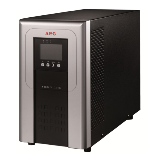
5. ÜBERSICHT ANSCHLÜSSE, BEDIEN-/ANZEIGEELEMENTE VORDERANSICHT Protect C.1000 Protect C.2000 Protect C.3000 Protect C.1000 BP Protect C.2030 BP... -
Page 24: Rückseitige Ansicht (Anschlüsse)
RÜCKSEITIGE ANSICHT (ANSCHLÜSSE) Protect C.1000 Protect C.2000 Protect C.3000... - Page 25 USB oder RS232 Schnittstelle genutzt werden. Anschluss für externe Batterieerweiterung Verbraucheranschlüsse (USV-Abgänge) IEC 320 C13 (10 A) Getrennte Absicherung der Laststromkreise beim PROTECT C.3000 Verbraucheranschluss PROTECT C.3000 (USV-Abgang) IEC 320 C19 (16 A) Verbraucheranschluss PROTECT C.3000 (USV-Abgang) über Klemmleiste...
-
Page 26: Inbetriebnahme
6. INBETRIEBNAHME AUFSTELLUNG Beim Aufstellen der USV-Anlage und deren externen Batterieeinheiten (Sonderzubehör) ist folgendes zu beachten: Die Auflagefläche muss glattflächig und zur Vermeidung von Vibratio- nen und Stößen ausreichende Festigkeit und Stabilität aufweisen. Achten Sie auf ausreichende Tragfähigkeit, insbesondere beim Ein- ... -
Page 27: Erweiterung Durch Externe Batteriemodule
Produkte miteinander: Protect C.1000 mit Protect C.1000 BP Protect C.2000 mit Protect C.2030 BP Protect C.3000 mit Protect C.2030 BP Protect C mit 1 Batterieerweiterung Abb.: Protect C.1000 und Protect C.1000 BP Überprüfen Sie die korrekte Zusammengehörigkeit von USV und Batterieeinheit (die Gehäuse müssen z. -
Page 28: Netzanschluss
Protect C mit 2 Batterieerweiterungen Abb.: Protect C.1000 und Protect C.1000 BP Überprüfen Sie die korrekte Zusammengehörigkeit von USV und Batterieeinheit (die Gehäuse müssen z. B. von den Abmessungen her identisch sein). Verbinden Sie mit den beiliegenden Batterieanschlussleitun- gen die entsprechenden Batteriekonnektoren gemäß obiger Abbildung. -
Page 29: Verbraucheranschluss
Schutzkontaktsteckdose. Achten Sie auf eine ausreichende Dimensionierung der Sicherung in Ihrer Unterver- teilung. Insbesondere der Protect C.3000 benötigt eine eigene Absiche- rung mit 16 A. Stecken Sie den Schutzkontaktstecker der Netzan- schlussleitung zunächst noch nicht in die dafür vorgesehene Schutzkon- taktsteckdose. - Page 30 Niemals zusätzliche Verbraucher an die USV anschließen oder zuschalten, wenn Netzausfall vorliegt, d.h. die USV im Notstrombetrieb arbeitet! In der Regel sollte, wenn im Normalbetrieb niemals Überlast aufgetreten ist, es auch im Batteriebetrieb zu keiner Überlast kommen. Ein Aufleuchten der LED Störung in Verbindung mit einem Signalton weist auf eine abschaltende Störung hin.
-
Page 31: Betrieb Und Bedienung
Ihrer Unterverteilung. Es erfolgt automatisch die Versorgung der USV mit Spannung aus dem öffentlichen Netz. Die USV startet mit der Initialisierungsphase, angezeigt durch ein für 5 Sekunden eingeblendetes AEG Logo. Danach erscheint (bei der Erstinbetriebnahme auf Englisch) nachstehende Meldung: UPS On USV Ein Die invertiert dargestellte Befehlsaufforderung „UPS On“... -
Page 32: Bedientableau
Zum leichteren Wiederauffinden dieses Menüpunktes „USV einschalten“ bzw. „USV ausschalten“ wird über der Taste „▲“ das Symbol eingeblendet. BEDIENTABLEAU 7.2.1 ÜBERBLICK Wesentliches Merkmal des Bedientableaus ist dessen grafisches LC Display mit Klartextanzeige. Im unteren Bereich befinden sich 4 Tasten zur Menü-navigation, der obere Bereich beinhaltet zusätzlich 3 verschiedenfarbige LEDs. -
Page 33: Bedientasten (Navigation)
7.2.3 BEDIENTASTEN (NAVIGATION) Die 4 Tasten zur Navigation beinhalten die folgenden Funktionen: „▲“ Taste: durch Drücken dieser Taste scrollen Sie in den Menüebenen nach oben bzw. verändern den einzustellenden Wert. Drücken Sie diese Taste während der Statusanzeige, so gelangen Sie zu dem Menüpunkt „USV ein- bzw. -
Page 34: Display (Hauptmenü)
DISPLAY (HAUPTMENÜ) Das Hauptmenü erreichen Sie durch Drücken der Taste „ESC“. Hauptmenü der LCD Anzeige (links die voreingestellte englische, rechts die deutsche Version) Die nachstehenden Abbildungen zeigen ausschließlich die Display- darstellung auf Deutsch (Umstellung siehe Kapitel 7.3.6 auf Seite 41ff. „Settings“... - Page 35 Das Display zeigt mittig im oberen Bereich den aktuellen USV Status an. Finden Sie im Folgenden eine Aufstellung der verwendeten Symbole und deren Bedeutung: Anzeige Status USV befindet sich im Normal- / Dauerwandlerbetrieb. Netz ist vorhanden und innerhalb des akzeptierten Toleranzfensters (Betriebsart: „Beste Leistung“).
- Page 36 USV führt aktuell einen Batterietest durch. Anzeige für 10 Sekunden nach erfolgreich durchgeführtem Batterietest. USV meldet fehlerhaftes bzw. nicht angeschlossenes Batteriesystem. USV ist überlastet. USV zeigt kritischen Fehler und hat den USV Ausgang abgeschaltet. Genereller USV Alarm. Details ersichtlich aus den Alarmmeldungen und Einträgen im Ereignisprotokoll.
- Page 37 Mitteilungen und Alarmmeldungen Teil 2 der USV Status - Anzeige erreichen Sie nach Drücken der Taste „▼“ und beinhaltet aktuelle Mitteilungen und ggf. anstehende Alarmmeldungen. Jede Mitteilung bzw. jeder Alarm wird in einem eigenen Fenster dargestellt und sequentiell durch Drücken der Taste „▼“...
-
Page 38: Ereignisprotokoll
7.3.2 EREIGNISPROTOKOLL Bis zu 50 Ereignisse werden im USV internen nichtflüchtigen Ereignis- speicher abgelegt. Das zuletzt aufgetretene Ereignis wird zuerst angezeigt, gefolgt von den weiter zurückliegenden. Jedes Ereignis wird analog zu den Mitteilungen und Alarm Meldungen in einem eigenen Fenster angezeigt. Die Darstellung eines Ereignisses erfolgt jeweils mit Datum und Uhrzeit, gefolgt von einer Beschreibung in Klartext. -
Page 39: Messwerte
7.3.3 MESSWERTE Durch Aufruf dieses Menüpunktes können Sie sequentiell nachstehende Messwerte abrufen: Systemwirkungsgrad Ausgang [W] & [VA] (Wirk- und Scheinleistung) Ausgang (Strom und Leistungsfaktor) Ausgang [V] & [Hz] (Spannung und Frequenz) Eingang [V] & [Hz] (Spannung und Frequenz) Batterie [V] & [%] (Spannung und Ladezustand) DC bus (Zwischenkreisspg.) Externe Batteriemodule... -
Page 40: Identifikation
„Steuerung“ / Befehl Beschreibung Umschaltung auf Bypassbetrieb Möglichkeit der bzw. Umschaltung auf Normal- Betriebszustandsänderung betrieb Menüpunkt nur sichtbar, wenn sich die USV momentan im Bypass- oder Normalbetriebs- zustand befindet. Batterietest Führt nach Bestätigung Batterietest durch. Auf Wunsch jederzeit Abbruch möglich. Fehlerspeicher löschen Zurücksetzen von Alarmmeldungen Löscht manuell alle aufgelaufenen... -
Page 41: Einstellungen
7.3.6 EINSTELLUNGEN Nachstehende Übersicht gibt eine detaillierte Beschreibung der möglichen Anwendereinstellungen über das USV Bedientableau wieder: Beschreibung Einstellbare Parameter Voreinstellung Sprachen [Englisch], [Deutsch], [Französisch], Englisch auswahl [Spanisch], [Russisch] Anm. Reihenfolge der Sprachenauswahl abhängig von aktueller Auswahl. Anwender [aktiv<AAAA>], [inaktiv] inaktiv passwort Passwort kann aus Buchstaben A~z und / oder Zahlen 0~9 bestehen (An-... - Page 42 Beschreibung Einstellbare Parameter Voreinstellung Steuerung [aktiv], [inaktiv] aktiv über serielle Kommunikation über RS232, USB Schnittstelle oder Karten im Kommunikationsslot nur bei Einstellung „aktiv“, ansonsten eingeschränkte Befehlsentgegen- nahme nur über das USV eigene LCD Display. Ausgangs- [200V], [208V], [220V], [230V], automatische spannung [240V], [automatische Erkennung] Erkennung...
- Page 43 Beschreibung Einstellbare Parameter Voreinstellung Externe Legt die Anzahl der externen <0> Batteriemodule Batterieeinheiten fest Batterie- [0%], [10%], [20%], …[100%] kapazität % USV Verbraucherzuschaltung erst für Wieder- nach Erreichen der voreingestellten anlauf Batteriemindestkapazitätsschwelle. Automatischer [aktiv], [inaktiv] aktiv Batterietest Periodischer [täglich], [wöchentlich], [monatlich] wöchentlich Batterietest Ein aktivierter automatischer Batterietest wird wiederkehrend entspre-...
- Page 44 Beschreibung Einstellbare Parameter Voreinstellung Warnung: [aktiv], [inaktiv] aktiv Erhöhte voreingestellte Warnschwelle Umgebungs- bei >40 °C temperatur Betriebsart [Öffner (N.C.)], [Schließer (N.O.)] Öffner (N.C.) Notabschalt- Einstellung „Öffner (N.C.)“ bedeutet kontakt eine Abschaltung bei Unterbrechen der Notabschaltschleife (Normally Closed). Einstellung „Schließer (N.O.)“ bedeutet eine Abschaltung bei Schließen der Notabschaltschleife (Normally Open).
- Page 45 Beschreibung Einstellbare Parameter Voreinstellung Automatischer [aktiv], [inaktiv] aktiv Bypass Einstellung „aktiv“ bedeutet: die USV aktiviert nach Anlegen der Netzspannung automatisch den internen Bypass und versorgt unverzüglich die angeschlossenen Verbraucher, dto. bei „Ausschalten“ der USV [aktiv], [inaktiv] inaktiv Anlauf ohne Einstellung „aktiv“ bedeutet: die USV Batterie kann auch ohne eingesetztes Batteriesystem gestartet werden.
-
Page 46: Schnittstellen Und Kommunikation
Statusmeldungen und Messwerten stehen Ihnen verschiedene Schnitt- stellen zur Verfügung. Das Schnittstellenprotokoll ist ausgerichtet auf den Betrieb mit der Shutdown und USV Management Software „CompuWatch“ von AEG. Benutzen Sie zum Anschluss Ihrer USV an den PC z. B. die dem Lieferumfang beigefügte USB Kommunikations- leitung. -
Page 47: Shutdown- Und Usv Management Software
SHUTDOWN- UND USV MANAGEMENT SOFTWARE Die speziell für diese Zwecke entwickelte AEG Software „CompuWatch“ kontrolliert kontinuierlich die Netzspeisung und den Zustand der USV. Im Zusammenspiel mit der „intelligenten“ USV wird sichergestellt, dass die Verfügbarkeit der EDV Komponenten sowie die Datensicherheit gewährleistet werden. -
Page 48: Notabschaltung Epo (Emergency Power Off)
NOTABSCHALTUNG EPO (EMERGENCY POWER OFF) Alle Geräte der Protect C Baureihe verfügen über einen Anschluss, der das unverzügliche Abschalten des USV- Ausgangs zum Freischalten angeschlossener Geräte gestattet und nicht dem Shutdown-Verfahren der Steuerungs-Software folgt. Hinweis Nach Betätigung der Notabschaltung sind die Ausgänge der USV span- nungsfrei. -
Page 49: Problembehandlung
9. PROBLEMBEHANDLUNG STÖRUNGEN Der Protect C setzt detaillierte Fehlermeldungen ab, mit denen Sie oder das Servicepersonal schnell und präzise auftretende Störungen lokalisieren und deuten können. Finden Sie nachstehend Verfahrens-/ Lösungsvorschläge zur Behebung des anstehenden Problems. Sollten Sie keine Lösung des aufgetretenen Problems herbeiführen können, beenden Sie den gesamten Vorgang, schalten Sie die USV aus, und trennen Sie die USV vom Netz. - Page 50 Alarm oder Anm. Mögliche Ursache Anm./Lösungsweg USV im USV hat z. B. aufgrund Wechselrichter der USV Batteriebetrieb eines Netzausfalls auf speist Verbraucher (Anmerkung #168) Batteriebetrieb geschaltet. über die USV interne Intermittierender Batterie. Versuchen Sie Signalton die Netzspg. wieder- herzustellen (ausgelöste Sicherung auf der USV Rückseite / in Ihrer Unterverteilung;...
- Page 51 Alarm oder Anm. Mögliche Ursache Anm./Lösungsweg Service Fehler im Batteriekreis; Batteriesystem Batteriesystem internes Ladeteil wird checken. Bleibt das (Alarm #149) deaktiviert. Problem bestehen, Kontinuierlicher setzen Sie sich mit Signalton Ihrem Händler in Verbindung. Netzfehler Eingang Netzspannungsver- Betriebszustandsbe- (Alarm #59) sorgung unterbrochen. zogen wechselt die USV Intermittierender in den Batteriebetrieb...
- Page 52 Alarm oder Anm. Mögliche Ursache Anm./Lösungsweg Überlast Ausgang Überlastung der USV Überprüfen Sie am (Alarm #25) Anlage. Display die Auslastung Intermittierender der USV. Reduzieren Signalton Sie ggf. die Last durch Abtrennung eines Teils Ihrer Verbraucher. DC Überspannung Die Spannung im Die USV schaltet zum Batterie Gleichspannungs-...
- Page 53 Alarm oder Anm. Mögliche Ursache Anm./Lösungsweg Lüfterfehler Die USV hat einen Ggf. Reinigung (Alarm #193) oder mehrere nicht aufgrund erhöhtem Kontinuierlicher ordnungsgemäß Staubanfall; Signalton funktionierende(n) Lüfterfunktion prüfen, Lüfter detektiert. ggf. Lüfter tauschen. Setzen Sie sich mit Ihrem Händler in Verbindung. Schwerwiegender Überprüfung der im Flash Datei überprüfen,...
-
Page 54: Wartung
WARTUNG Der Protect C besteht aus modernen und verschleißarmen Bauelemen- ten. Dennoch ist es empfehlenswert, zur Aufrechterhaltung der ständi- gen Verfügbarkeit und der Betriebssicherheit, in regelmäßigen Abstän- den (mindestens jedoch alle 6 Monate) Sichtkontrollen (vor allem Batte- rie- und Lüfterkontrollen) durchzuführen. Vorsicht! Arbeitsbereichabsicherung und die Sicherheitsvorschriften unbedingt beachten! -
Page 55: Batteriekontrolle
Bei sehr starkem Staubanfall sollte das Gerät vorsorglich mit trockener Pressluft ausgeblasen werden, um einen besseren Wärmeaustausch zu ermöglichen. Die Zeitabstände der durchzuführenden Sichtkontrollen hängen in erster Linie von den örtlichen Aufstellungsgegebenheiten der Geräte ab. 10.2.2 BATTERIEKONTROLLE Der fortschreitende Alterungszustand des Batteriesystems lässt sich durch regelmäßige Kapazitätsproben erkennen. - Page 56 Hinweis Sollten Sie auch externe Batteriesysteme einsetzen, so empfehlen wir aus technischen Gründen heraus eindringlich den Wechsel aller Batteriesysteme. Entsorgung von gebrauchten Batterien und Akkumulatoren (anzuwenden in den Ländern der europäischen Union und anderen europäischen Ländern mit einem separaten Sammelsystem für diese Produkte).
-
Page 57: Lagerung, Demontage Und Entsorgung
LAGERUNG, DEMONTAGE UND ENTSORGUNG 11.1 LAGERUNG Lange Lagerzeiten ohne gelegentliches Aufladen bzw. Entladen können zu einer dauerhaften Schädigung der Batterie führen. Wenn die Batterie bei Raumtemperatur (20 °C bis 30 °C) gelagert wird, kommt es aufgrund innerer Reaktionen zu einer Selbstentladung von 3 –... - Page 58 Das Symbol auf dem Produkt oder seiner Verpackung weist darauf hin, dass dieses Produkt nicht als normaler Haushaltsabfall zu behandeln ist, sondern an einer Annahmestelle für das Recycling von elektrischen und elektronischen Geräten abgegeben werden muss. Durch Ihren Beitrag zum korrekten Entsorgen dieses Produkts schützen Sie die Umwelt und die Gesundheit Ihrer Mitmenschen.
-
Page 59: Anhang
ANHANG 12.1 SACHWORTVERZEICHNIS (TECHNISCHE BEGRIFFE) DC/DC Booster Schaltungstechnik zur Anhebung einer Gleichspannung auf ein höheres Spannungsniveau Geräteschutz Begriff aus der Überspannungstechnik Der klassische Netzüberspannungsschutz besteht aus Blitzstromableiter (Klasse B), einem Überspannungs- schutz (Klasse C) und dem sog. Geräteschutz (Klasse D) IGBT Insulated Gate Bipolar Transistor Hochleistungsfähige Transistoren modernster... - Page 60 Output Voltage Independent from mains supply Der USV-Ausgang ist abhängig von Netzfrequenzschwankungen, jedoch wird die Netzspannung durch elektronische / passive Spannungsregelgeräte aufbereitet. Frühere Bezeichnung: LINE-INTERACTIVE Output Voltage and Frequency Independent from mains supply. Der USV-Ausgang ist unabhängig von Netzspannungs- und Frequenzschwankungen. Frühere Bezeichnung: ONLINE...
-
Page 61: Stichwortregister
12.2 STICHWORTREGISTER Abmessungen Lagerung Anschlüsse 23, 24 Lieferumfang Anzeigen Aufstellungsort Messwertanzeige Montage Batteriebetrieb Batterietest 36, 43 Batterieerweiterung Netzanschluss Bedientableau Normalbetrieb Betriebszustände Notabschaltung Bypassbetrieb 10, 32 Richtlinien CE - Erklärung RS 232 Interface 25, 46 Display Schnittstellen (PC) Sicherheitshinweise Signalisierungen Einstellungen Störungen Systembeschreibung Geräteüberlast... - Page 62 NOTIZEN...
- Page 63 NOTIZEN...
- Page 65 Thank you for purchasing the AEG UPS PROTECT C from AEG Power Solutions. Safety information and operating instructions are included in this manual. To ensure correct use of the UPS, please read this manual thoroughly before operating it. Use this manual properly.
- Page 66 CONTENT Notes on these Operating Instructions ....68 General Information ..........70 Technology ..............70 System Description ............. 71 Technical information ..........73 Safety ................ 78 General Safety Instructions ......... 78 ...
- Page 67 7.3.4 Control .............. 101 7.3.5 Identification ............102 7.3.6 Settings ............. 103 Interfaces and communication ......108 RS232 and USB Computer Interfaces ...... 108 Communication slot ..........108 ...
-
Page 68: Notes On These Operating Instructions
These operating instructions will help you to install and operate the Uninterruptible Power Supply (UPS) PROTECT C.1000, PROTECT C.2000 or PROTECT C.3000 as well as the associated external battery units PROTECT C.1000 BP or PROTECT C.2030 BP – all referred to as PROTECT C in this document –... - Page 69 Tel: +49 2902 763100 Internet: www.aegps.com COPYRIGHT No part of these operating instructions may be transmitted, reproduced and/or copied by any electronic or mechanical means without the express prior written permission of AEG. © Copyright AEG 2014. All rights reserved.
-
Page 70: General Information
2. GENERAL INFORMATION TECHNOLOGY PROTECT C is an Uninterruptible Power Supply (UPS) for essential loads such as PCs, workstations, servers, network components, telecommunication equipment and similar devices. It consists of: Mains filter with surge voltage protection (device protection/ class D) and mains energy backfeed protection Rectifier section with PFC logic (power factor correction unit) ... -
Page 71: System Description
SYSTEM DESCRIPTION The UPS is connected to a shockproof socket between the public utility’s mains and the loads to be protected. The power section of the rectifier converts the mains voltage to DC voltage for supplying the inverter. The circuit technology used (PFC) enables sinusoidal current consumption and therefore operation with little system disturbance. - Page 72 The automatic bypass serves to increase the reliability of the supply further. It switches the public mains directly through to the load if there is an inverter malfunction. As a result, the automatic bypass represents an extra passive redundancy for the load. The graphical LC display used provides for versatile use and easy operation.
-
Page 73: Technical Information
Protect C.1000 1000 VA (cos φ = 0.8 lag.) 800 W Protect C.2000 2000 VA (cos φ = 0.8 lag.) 1600 W Protect C.3000 3000 VA (cos φ = 0.8 lag.) 2400 W UPS Input 1ph~ / N / PE... - Page 74 21 min. 2 add. battery modules 51 min. 70 min. 45 min. Battery check daily; weekly; monthly (programmable) Rated DC voltage (intermediate circuit) Protect C.1000 36 VDC Protect C.2000 96 VDC Protect C.3000 96 VDC Battery charging current 1 ADC (max.)
- Page 75 (VRLA) Protect C.1000 12 V 7 Ah x 3 Protect C.2000 12 V 7 Ah x 8 Protect C.3000 12 V 7 Ah x 8 Protect C.1000 BP 12 V 7 Ah x 3 x 2 Protect C.2030 BP...
- Page 76 IP20 Outlets Protect C.1000 4 x IEC 320 C13 Protect C.2000 6 x IEC 320 C13 Protect C.3000 4 x IEC 320 C13 +1 x IEC 320 C19 +1 fixed connection on terminal block Display Graphic LCD, resolution: 128 x 64 pixels...
- Page 77 Protect C.1000 BP 300 mm x 330 mm x 500 mm Protect C.2000 330 mm x 475 mm x 590 mm Protect C.3000 330 mm x 475 mm x 590 mm Protect C.2030 BP 330 mm x 475 mm x 590 mm...
-
Page 78: Safety
3. SAFETY GENERAL SAFETY INSTRUCTIONS Read these operating instructions prior to start-up of the PROTECT C UPS and its external battery modules (special accessories), and observe the safety instructions. Only use the unit if it is in a technically perfect condition and always in accordance with its intended purpose, while being aware of safety and danger aspects, and in accordance with the operating instructions! Immediately eliminate any faults that could be detrimental to safety. -
Page 79: Safety Instructions For Protect C
SAFETY INSTRUCTIONS FOR PROTECT C This chapter contains important instructions for the PROTECT C UPS and its external battery modules (special accessories). These must be followed during assembly, operation and maintenance of the uninterruptible power supply and the battery systems (internal and, if appropriate, external as well). - Page 80 Observe the following safety instructions to ensure permanent operational safety of and safe work with the UPS and the battery modules (special accessories): Do not dismantle the UPS! (The UPS does not contain any parts that require regular maintenance. Bear in mind that the warranty will be invalidated if the unit is opened!) Do not install the unit in direct sunshine or in close proximity of ...
- Page 81 Only authorised persons are allowed in the vicinity of the batteries! When replacing the batteries, the following must be observed: Only ever use identical maintenance-free sealed lead batteries with the same data as the original batteries. Only authorised persons are allowed in the vicinity of the batteries! When replacing the batteries, the following must be observed: Only ever use identical maintenance-free sealed lead batteries with the same data as the original batteries.
-
Page 82: Ce-Certificate
CE-CERTIFICATE... -
Page 83: Set-Up And Operation
Don’t turn on the unit and register the damage with the AEG representative or dealer immediately. -
Page 84: Point Of Installation
Please keep the plastic packaging bags away from babies and children in order to safeguard against suffocation accidents. Handle the components with care. Please take into account the weight. It may be necessary to engage the help of a second person, particularly in the case of the 2 and 3 kVA models and if there are external battery units. -
Page 85: Elements
5. OVERVIEW CONNECTIONS, OPERATING / DISPLAY ELEMENTS FRONT VIEW Protect C.1000 Protect C.2000 Protect C.3000 Protect C.1000 BP Protect C.2030 BP... -
Page 86: Rear View (Connections)
REAR VIEW (CONNECTIONS) Protect C.1000 Protect C.2000 Protect C.3000... - Page 87 Consumer connectors (UPS output) IEC 320 C13 (10 A) 10. Separate protection of load circuits for PROTECT C.3000 11. Consumer connection PROTECT C.3000 (UPS output) IEC 320 C19 (16 A) 12. Consumer connection PROTECT C.3000 (UPS output) via terminal block...
-
Page 88: Commissioning
6. COMMISSIONING MECHANICAL SET-UP Note the following points when setting up the UPS system and its external battery units (special accessories): The contact surface must be smooth and level. It must also be sufficiently strong and sturdy to avoid vibration and shock loads. Make sure the mounting is able to support the weight: This is ... -
Page 89: External Battery Extension
Connect exclusively the following products together Protect C.1000 with Protect C.1000 BP Protect C.2000 with Protect C.2030 BP Protect C.3000 with Protect C.2030 BP Protect C with 1 battery extension Fig.: Protect C.1000 and Protect C.1000 BP Check the correct fit of the UPS and the battery unit (the casings e.g. -
Page 90: Power Supply
Protect C with 2 battery extensions Fig.: Protect C.1000 und Protect C.1000 BP Check the correct fit of the UPS and the battery unit (the casings e.g. have to have the same dimension). Now connect the corresponding battery connectors using the supplied battery connection cables as shown in the figure above. -
Page 91: Consumer Connection
Protect C series connection is made via the supplied mains lead to a standard electrical outlet. Utilize a sufficient fuse rating in your sub-distribution. In particular, the Protect C.3000 requires its own 16 A protection. Initially, do not yet insert the safety plug of the power cord in the dedicated electrical outlet. - Page 92 Never connect additional loads to the UPS or switch on during a power failure, e.g. if the UPS is operating in emergency mode! As a rule, if there has never been an overload during normal operation, Battery mode operation will also not have suffered an overload. A flash of the LED fault in connection with a beep indicates a deactivating fault.
-
Page 93: Operation And Usage
The UPS will be immediately supplied with power from the public power network. It will start up with an initialization phase, indicated by the AEG logo, which appears on the screen for 5 seconds. After that, you will see the following message: UPS On Now confirm the highlighted “UPS On”... -
Page 94: Control Panel
CONTROL PANEL 7.2.1 OVERVIEW An essential feature of the control panel is the graphical LCD with plain text display. In the lower section 4 buttons are available for menu navigation, the upper range also includes 3 different colored LEDs. Fig.: Display “UPS status” display 7.2.2 INDICATORS (LEDS) The indicators (LEDs) show the following different modes: Display... -
Page 95: Operating (Navigation)
7.2.3 OPERATING (NAVIGATION) The 4 keys for navigation control the following functions: “▲” Key: Press this key to scroll upwards in the menu levels or to alter a value you want to set. If you press this key in the status display, you will access the “UPS On or Off”... -
Page 96: Display (Main Menu)
DISPLAY (MAIN MENU) Press “ESC” to access the main menu. Main menu for the LCD display The following figures show the display in English (to change the language see Chapter 7.3.6 on page 103 (“Settings”). 7.3.1 UPS STATUS DISPLAY You can access the status screen by pressing “▲” or “▼” in the main menu to go to “UPS Status”... - Page 97 The display indicates the current UPS status in the top middle section. Here is a list of the symbols used and what they mean: Display Status UPS is in normal / continuous double- conversion mode. Power supply is available and within the acceptable tolerance range (Mode: “High performance”).
- Page 98 UPS is testing the battery. Display for 10 seconds after a successful battery test. UPS reports a defective or disconnected battery system. UPS is overloaded. UPS indicates a critical error and has switched off the UPS output. General UPS alarm. Details can be found in the Alarm messages and entries in the event log.
- Page 99 Messages and alarms Press “▼” to access part 2 of the UPS status display. It contains current messages and alarms, if any. Each message or each alarm is displayed in its own window and you can press “▼” to scroll through them. If there is no information available, the following message will appear: “No active alarms”.
-
Page 100: Event Log
7.3.2 EVENT LOG Up to 50 events are stored in the internal non-volatile event memory in the UPS. The last event that occurred is the first on the list, followed by other previous events. Similar to the messages and alarms, each event is shown in its own window. -
Page 101: Measurements
7.3.3 MEASUREMENTS Select this menu item to find the following measurements in this order: Power Usage Efficiency Output [W] & [VA] (active and apparent power) Output (current and power factor) Output [V] & [Hz] (voltage and frequency) Input [V] & [Hz] (voltage and frequency) Battery [V] &... -
Page 102: Identification
”Control” / Command Beschreibung Go to Bypass / Normal Possibility to change operation mode. If the UPS is not in Normal Mode or Bypass Mode this option is not used and should not be displayed as a control option. Battery Test Schedule Battery Test: yes | Cancel Battery test: no Starts a manual battery test. -
Page 103: Settings
7.3.6 SETTINGS The following table provides you with a detailed description of the possible user settings using the UPS operating panel: Description Adjustable parameters Presetting Change [English], [German], [French], English language [Spanish], [Russian] Note: Language selection order depends on initial selection. User password [enabled<AAAA>] [disabled] disabled... - Page 104 Description Adjustable parameters Presetting Control [enabled], [disabled] enabled commands If enabled, control commands are from serial port accepted through Serial, USB port and cards in the communication slot, else control is restricted to the LCD panel of the UPS. [200V], [208V], [220V], [230V], auto-sensing Output [240V], [auto-sensing]...
- Page 105 Description Adjustable parameters Presetting External battery Configures the amount of <0> modules external battery units Battery charged [0%], [10%], [20%], ...[100%] % to restart On battery operation the UPS output is turned off as soon as the battery capacity is below the selected level. [enabled], [disabled] Automatic enabled...
- Page 106 Description Adjustable parameters Presetting Ambient [enabled], [disabled] enabled temperature If enabled, UPS alarm when ambient warning temperature >40 °C REPO [normally open], [normally closed] normally closed operation Normally open means UPS makes a shutdown by a closing input state. Normally closed means UPS makes a shutdown by an opening input state.
- Page 107 Description Adjustable parameters Presetting Auto bypass [enabled], [disabled] enabled “enabled” means UPS will have bypass output when utility power on. “disabled” means UPS will not have bypass output when power on but could get bypass output when UPS is fault or overload. Start without [enabled], [disabled] disabled...
-
Page 108: Interfaces And Communication
The interface log is designed to be used with “CompuWatch”, the shutdown and UPS management software from AEG. Use the USB communication cable, for example, that comes with the device to connect your UPS to a The USB and the RS232 communication interface rule each other out, i.e. -
Page 109: Shutdown- Und Ups Management Software
SHUTDOWN- UND UPS MANAGEMENT SOFTWARE The "CompuWatch" software specially developed for these purposes by AEG continuously checks the mains supply and the UPS status. In conjunction with the "intelligent" UPS, this ensures that the availability of IT components and data security is guaranteed. -
Page 110: Epo (Emergency Power Off)
EPO (EMERGENCY POWER OFF) All the devices in the PROTECT C series are equipped with a connection that allows the immediate shutdown of the UPS output to deactivate any devices connected and does not follow the control software shutdown process. Note Once the emergency power off has been activated, the UPS outputs are voltage-free. -
Page 111: Trouble Shooting
9. TROUBLE SHOOTING MALFUNCTIONS The PROTECT C issues detailed error messages to help you or the maintenance staff to localize and interpret any malfunctions that may occur quickly and with high precision. In the following, please find process / solution suggestions to eliminate the problem that has occurred. - Page 112 Alarm or Notice Possible cause Remark / Action UPS on Battery A utility failure has The UPS is powering (Notice #168) occurred and the UPS the equipment with Intermittent Alarm is in Battery mode. battery power. Prepare your equipment for shutdown.
- Page 113 Alarm or Notice Possible cause Remark / Action Service Battery A faulted battery string Contact your service (Alarm #149) has been detected and representative. Continuous Alarm as a result, the charger is disabled. Utility Not Present The utility power level The uninterruptible (Alarm #59) has fallen below the...
- Page 114 Alarm or Notice Possible cause Remark / Action Output Overload The load level is at The UPS can support (Alarm #25) or has exceeded the the load indefinitely at Intermittent Alarm configurable threshold this load level. limit for a Overload The alarm clears when condition.
- Page 115 Alarm or Notice Possible cause Remark / Action Fan Failure The uninterruptible This is an alarm only. (Alarm #193) power supply has Contact your service Continuous Alarm detected that one or representative more fans are not immediately and functioning correctly. remove the load.
-
Page 116: Maintenance
MAINTENANCE The PROTECT C consists of advanced and resistant components. To guarantee a continuous and high availability it is recommended to check the unit (especially the batteries and the fans) in regular intervals (at least every 6 months). Caution! Follow safety and security regulations unconditionally! 10.1 BATTERY CHARGING The battery is automatically charged when the mains is present, irrespective of the operating mode. -
Page 117: Checking The Battery
If large quantities of dust have accumulated, the unit should, as a precaution, be cleaned with dry compressed air, in order to ensure adequate heat dissipation. The intervals at which visual checks should be performed are largely determined by the site conditions. 10.2.2 CHECKING THE BATTERY Progressive ageing of the battery system can be detected by regular capacity checks. - Page 118 Note If the UPS will be operated with additional external battery packs we recommend from technical point of view to replace all battery systems at the same time. Replace the EBM battery system same as the UPS replacement, ensure a proper connection.. Disposal of waste batteries (applicable in the European Union and other European countries with separate collection systems) This symbol on the battery or on the packaging indicates that the battery...
-
Page 119: Storage, Dismantling And Disposal
STORAGE, DISMANTLING AND DISPOSAL 11.1 STORAGE Long storage times without charging or discharging the battery at regular intervals may lead to permanent damage of the battery.. Long storage times without charging or discharging the battery at regular intervals may lead to permanent damage of the battery. If the battery is stored at room temperature (20°... - Page 120 This symbol on the product or on is packaging indicates that this product shall not be treated as household waste. Instead it shall be handled over the applicable collection point for the recycling of electrical and electronic equipment. By ensuring this product is disposed of correctly, you will help prevent potential negative consequences for the environment and human health, which could otherwise be caused by inappropriate waste handling of this product.
-
Page 121: Glossary
GLOSSARY 12.1 TECHNICAL TERMS DC/DC Booster Circuit technology to boost the direct voltage on a higher voltage level Device Technology term of the surge voltage protection: protection the conventional surge voltage protection consists of a lightning current protection (class B, class I), a surge voltage protection (class C, class II) and an equipment protection (class D, class III) IGBT... - Page 122 Output Voltage and Frequency Dependent from mains supply. The UPS output depends of mains voltage and frequency variations. Former notation: OFFLINE Output Voltage Independent from mains supply The UPS output is independent of mains voltage and frequency variations. The mains voltage however is rectified by electronic / passive voltage regulators.
-
Page 123: Key Word Register
12.2 KEY WORD REGISTER Assembly Malfunctions Autonomy time Measurement indicator Battery extension Normal mode Battery mode 97, 99 Battery test 98,101 Bypass mode Operating States Overload CE - Certificate Cold Start 80, 104 Power supply Communication Connections 85, 86 Control Panel RS 232 interface 87, 108 Device Overload... - Page 124 NOTES NOTES...
- Page 125 NOTES...
- Page 126 NOTES...
- Page 128 GARANTIESCHEIN / GUARANTEE CERTIFICATE TYP / MODEL: GERÄTE-NR. / SERIAL-NO.: KAUFDATUM / DATE OF PURCHASE: HÄNDERSTEMPEL / UNTERSCHRIFT TRADING STAMP / SIGNATURE IRRTÜMER UND ÄNDERUNGEN VORBEHALTEN SPECIFICATIONS ARE SUBJECT TO CHANGE WITHOUT NOTICE BETRIEBSANLEITUNG 8000055650 BAL, DE OPERATING INSTRUCTIONS 8000055650 BAL, EN Emil-Siepmann-Str.