
Summary of Contents for Motorola PTP 800
- Page 1 PTP 8 00 Licensed Ethernet Microwave User Guide System Release 800-02-00 phn-1478_005v000 © 2009 - 2010 Motorola, Inc. All Rights Reserved.
- Page 2 Motorola, Inc. does not assume any liability arising out of the application or use of any product, software, or circuit described herein;...
-
Page 3: Important Safety Information
Exercise extreme care when working at heights. Grounding and protective earth The outdoor unit (ODU) and compact modem unit (CMU) for the PTP 800 must be properly grounded. It is the user’s responsibility to install the equipment in accordance with national regulations. In the USA, follow Section 810 of the National Electric Code, ANSI/NFPA No.70-1984... -
Page 4: Electrical Safety
Safety Electrical safety The power cable connections must meet International Electrotechnical Commission (IEC) safety standards. Always power down and unplug the equipment before servicing. When using alternative DC supplies, such as battery-backed DC power source, the supply must be SELV rated. Primary disconnect device The power supply must include a primary disconnect device with appropriate fusing. -
Page 5: Table Of Contents
About This User Guide ....................1 Revision History ........................2 Version information......................2 General information ........................3 Purpose ..........................3 Cross references .......................3 Text conventions .......................4 Contacting Motorola .......................5 Feedback ...........................5 Motorola Point-to-Point .....................5 Wireless Broadband Technical Support telephone numbers ..........5 Reporting problems......................7 Repair and service ......................7 Warranty ...........................7 Security advice........................9... - Page 6 Notes ..........................10 Caring for the environment ....................11 In EU countries .......................11 In non-EU countries ......................11 Licensing requirements ......................12 Operating license ......................12 Motorola license agreement ...................12 Chapter 1 Product description ..................1-1 Overview ..........................1-2 Key features ........................1-2 Typical users ........................1-3 Typical applications .......................1-3 Product variants......................1-4...
- Page 7 Priority for management traffic ...................2-17 IP interface........................2-17 Quality of service for bridged Ethernet traffic.............2-17 Fast Ethernet port shutdown ..................2-18 Chapter 3 Legal information ..................3-1 Motorola Inc. end user license agreement ................3-2 Definitions ........................3-2 Grant of license ......................3-2 Conditions of use......................3-3 phn-1478_005v000...
- Page 8 Contents Title and restrictions......................3-4 Confidentiality........................3-4 Right to use Motorola’s name ..................3-5 Transfer..........................3-5 Updates ..........................3-5 Maintenance ........................3-5 Disclaimer ........................3-6 Limitation of liability......................3-6 U.S. government ......................3-7 Term of license.......................3-7 Governing law ........................3-7 Assignment........................3-7 Survival of provisions.....................3-8 Entire agreement ......................3-8 Third party software ......................3-8 Hardware warranty......................3-13...
- Page 9 Contents Antenna specifications (11 GHz)..................4-17 Antenna specifications (18 GHz)..................4-19 Antenna specifications (23 GHz)..................4-20 Antenna specifications (26 GHz)..................4-21 Antenna specifications (38 GHz)..................4-22 Flexible waveguide specifications..................4-23 Waveguide flanges .......................4-23 Flexible waveguide specifications (Lower 6 GHz) ............4-28 Flexible waveguide specifications (7 GHz) ..............4-28 Flexible waveguide specifications (11 GHz) ..............4-29 Flexible waveguide specifications (18, 23 and 26 GHz) ..........4-29 Flexible waveguide specifications (38 GHz) ..............4-30...
- Page 10 Contents Inventory and tools ......................5-3 Standard PTP 800 components ..................5-3 Optional components .....................5-8 Tools required ......................5-12 Cable connection procedures.....................5-13 Preparing IF cables......................5-13 Waterproofing connectors ...................5-17 Installing the cable grounding kit................5-20 Direct mounting of antenna and ODU ................5-28 Direct mounting of antenna with a single ODU ............5-29 Direct mounting of antenna with two ODUs and coupler ..........5-33...
- Page 11 Contents Installation wizard......................5-91 Step 1: Configuring equipment parameters..............5-91 Step 2: Configuring radio license parameters .............5-95 Step 3: Configuring wireless parameters ..............5-98 Step 4: Confirming installation configuration..............5-99 Step 5: Starting antenna alignment ................5-101 Step 6: Aligning antennas ..................5-102 Step 7: completing installation ..................5-108 Connecting the CMU to the network ................5-109 Update security and capacity capabilities ..............5-109 Configure security......................5-109...
- Page 12 Checking capability summary ..................6-28 Using access keys to generate a new license key............6-29 Entering a license key....................6-30 Saving and restoring system configuration ..............6-31 Upgrading PTP 800 software ..................6-34 Managing security ......................6-37 Changing administrator password................6-37 Enabling AES encryption .....................6-38 Disabling AES encryption ....................6-40 Changing AES encryption keys ..................6-41...
- Page 13 Prerequisites ........................7-12 Entering recovery mode....................7-12 Selecting recovery option ....................7-14 Upgrading the software image ..................7-16 Resetting IP and Ethernet configuration to factory defaults ........7-17 Erasing configuration....................7-18 Zeroizing security parameters ..................7-19 Downgrading PTP 800 software...................7-20 Glossary ........................I Index........................III phn-1478_005v000 Apr 2010...
- Page 14 Figure 1-3 ODU ........................1-10 Figure 1-4 ODU (front, side and rear view) ................1-11 Figure 1-5 Typical PTP 800 antenna (Motorola direct mount interface) .......1-14 Figure 1-6 Direct mount mechanical interface ..............1-15 Figure 1-7 ODU clipped onto direct mount mechanical interface .........1-15 Figure 1-8 Remote mount antenna waveguide interface ............1-16...
- Page 15 Figure 5-13 Rack mounted CMU with a right angled IF cable connector ......5-74 Figure 5-14 CMU grounding ....................5-74 Figure 5-15 CMU ground connector ..................5-75 Figure 5-16 Motorola AC to DC converter ................5-75 Figure 5-17 Example of a cable analyzer ................5-77 Figure 5-18 Example of the cable test ...................5-78 Figure 5-19 Cable loss plot for a 17 meter cable with no ODU ..........5-80...
- Page 16 List of Figures Figure 5-34 Step 3: Wireless Configuration page (ETSI adaptive modulation) .....5-98 Figure 5-35 Step 4: Confirm Installation Configuration page..........5-100 Figure 5-36 Step 5: Start Antenna Alignment page .............5-101 Figure 5-37 Step 6: Configuration Complete page (step 5 cancelled) .........5-102 Figure 5-38 Step 6: Antenna Alignment page (searching for link) ........5-105 Figure 5-39 Step 6: Antenna Alignment page (link established) .........5-105 Figure 5-40 Alignment Abandoned ..................5-106...
- Page 17 List of Figures Figure 6-24 Reboot Wireless Unit page .................6-51 Figure 6-25 Clock section of Remote Management page (SNTP disabled)......6-52 Figure 6-26 Clock section of Remote Management page (SNTP enabled) ......6-54 Figure 6-27 System Statistics and Counters page ..............6-56 Figure 6-28 Diagnostics Plotter page..................6-60 Figure 6-29 Generate Downloadable Diagnostics page ............6-62 Figure 7-1 Recovery Mode Warning page................7-14 Figure 7-2 Recovery Options page ..................7-15...
- Page 18 ............Table 1-1 PTP 800 product variants ..................1-4 Table 1-2 CMU front panel interfaces..................1-6...
- Page 19 List of Tables Table 4-23 Antenna specifications for 26 GHz – single polarization ........4-21 Table 4-24 Antenna specifications for 26 GHz – dual polarization.........4-21 Table 4-25 Antenna specifications for 26 GHz – single polarization ........4-22 Table 4-26 Antenna specifications for 38 GHz – dual polarization.........4-22 Table 4-27 Antenna, transition, waveguide and RMK flanges ..........4-24 Table 4-28 Torque value in Nm (lb ft) for each fastener size..........4-27 Table 4-29 Flexible waveguide specifications –...
- Page 20 Table 4-91 EMC immunity compliance specifications............4-63 Table 4-92 PTP 800 minimum separation distances, ETSI method........4-68 Table 4-93 PTP 800 minimum separation distances, FCC method ........4-70 Table 5-1 Components of a standard PTP 800 installation ............5-3 Table 5-2 Components of the coaxial cable installation assembly kit ........5-6 Table 5-3 Optional components of a PTP 800 installation............5-8...
- Page 21 List of Tables Table 5-4 Tools required for PTP 800 installation..............5-12 Table 5-5 Expected cable loss when ODU is not connected...........5-83 Table 5-6 Step 1: Equipment Configuration attributes ............5-93 Table 5-7 Step 2: Radio License Configuration attributes .............5-97 Table 5-8 Step 3: Wireless Configuration attributes ..............5-99 Table 6-1 System Summary attributes ..................6-4...
- Page 22 List of Tables phn-1478_005v000 Apr 2010...
-
Page 23: About This User Guide
............This guide describes the planning, installation and operation of the Motorola PTP 800. -
Page 24: Revision History
Revision History Revision History Version information The following shows the issue status of this document since it was first released. Document Date of Remarks issue issue 001v000 Oct 2009 System Release 800-01-00 (original) 002v000 Oct 2009 System Release 800-01-00 (revised) 004v000 Dec 2009 System Release 800-01-00 (addition of 11 GHz ETSI) -
Page 25: General Information
It is recommended that all personnel engaged in such activities be properly trained. Motorola disclaims all liability whatsoever, implied or express, for any risk of damage, loss or reduction in system performance arising directly or indirectly out... -
Page 26: Text Conventions
General information Text conventions The following conventions are used in the Motorola Point-To-Point documents to represent keyboard input text, screen output text and special key sequences. Input Characters typed in at the keyboard are shown like this. Output Messages, prompts, file listings, directories, utilities, and environmental variables that appear on the screen are shown like this. -
Page 27: Contacting Motorola
Contacting Motorola Contacting Motorola Feedback We appreciate feedback from the users of our documents. This includes feedback on the structure, content, accuracy, or completeness of our documents. Send feedback to support.ptp@motorola.com. Motorola Point-to-Point Motorola, Inc., 1303 E. Algonquin Road, Schaumburg,... - Page 28 Contacting Motorola Region and country Support telephone number Germany 06950070204 Italy 0291483230 Lithuania 800 030 828 Netherlands 0202061404 Norway 24159815 Portugal 0217616160 Spain 912754787 Russia 810 800 228 41044 Saudi Arabia 800 844 5345 South Africa 0800981900 United Kingdom 0203 0277499...
-
Page 29: Reporting Problems
Motorola shall within this time, at its own option, either repair or replace the defective product within thirty (30) days of receipt of the defective product. - Page 30 Contacting Motorola For warranty assistance, contact the reseller or distributor. CAUTION Using non-Motorola parts for repair could damage the equipment or void warranty. Contact Motorola Warranty and Repair for service and repair instructions. CAUTION Portions of Motorola equipment may be damaged from exposure to electrostatic discharge.
-
Page 31: Security Advice
Security advice Security advice Motorola systems and equipment provide security parameters that can be configured by the operator based on their particular operating environment. Motorola recommends setting and using these parameters following industry recognized security practices. Security aspects to be considered are protecting the confidentiality, integrity, and availability of information and assets. -
Page 32: Warnings, Cautions, And Notes
Warnings, cautions, and notes Warnings, cautions, and notes The following describes how warnings and cautions are used in this document and in all documents of this Motorola document set. Warnings Warnings precede instructions that contain potentially hazardous situations. Warnings are used to alert the reader to possible hazards that could cause loss of life or physical injury. -
Page 33: Caring For The Environment
European Union (EU) Directive 2002/96/EC Waste Electrical and Electronic Equipment (WEEE) Do not dispose of Motorola equipment in landfill sites. In the EU, Motorola in conjunction with a recycling partner ensures that equipment is collected and recycled according to the requirements of EU environmental law. -
Page 34: Licensing Requirements
Operating license This equipment operates in bands that require a license in most countries. CAUTION In most countries it is illegal to operate the PTP 800 without a license from the regional or local regulating authority. United States of America... -
Page 35: Chapter 1 Product Description
............This chapter provides a high level description of the PTP 800 product. It describes in general terms the function of the product, the main product variants and typical deployment. -
Page 36: Overview
11 GHz, 18 GHz, 23 GHz, 26 GHz and 38 GHz licensed bands. PTP 800 provides link capacity from 10 Mbit/s to 368 Mbit/s with configurable ETSI and FCC channel bandwidths from 7 to 56 MHz. With upgradeable link capacity limits from 10 Mbit/s to full capacity via software key, the system offers exceptional cost efficiency and scalability. -
Page 37: Typical Users
Cellular carriers Health care and hospitals Schools and universities Municipalities Public safety agencies Typical applications PTP 800 systems serve a wide variety of enterprise and carrier network applications, including: Building-to-building connectivity Leased-line replacement Video surveillance Network redundancy WiMAX, LTE and 3G backhaul... -
Page 38: Product Variants
24.5 – 26.5 GHz 38 GHz ETSI 37.0 – 39.5 GHz System components The main components of the PTP 800 are: Compact modem unit (CMU): Optional capacity upgrades Optional security upgrades Optional fiber data interface Optional CMU rack mount kit... -
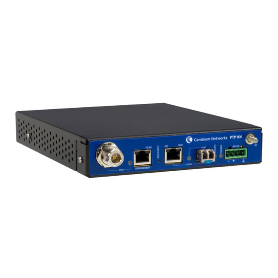
Page 39: Compact Modem Unit (Cmu)
User Guide: PTP 800 Licensed Ethernet Microwave Compact modem unit (CMU) Compact modem unit (CMU) The PTP 800 compact modem unit (CMU) (Figure 1-1) is used as a component of a line-of-sight licensed-band microwave link to deliver a point-to-point Ethernet service between two locations. -
Page 40: Front Panel
Compact modem unit (CMU) Chapter 1 Product description Front panel The CMU front panel is illustrated in Figure 1-2. The annotated interfaces are described in Table 1-2. Figure 1-2 CMU front panel Table 1-2 CMU front panel interfaces Number Description More information ODU connector ODU connector... - Page 41 Do not connect or disconnect the IF cable when the –48 V supply is applied to the CMU. Management port The PTP 800 system supports network management communications in two modes: “out-of-band” and “in-band”. In the “out-of-band” mode, the system is managed by connecting to the CMU through the management port.
- Page 42 Compact modem unit (CMU) Chapter 1 Product description Fiber SFP interface The Fiber SFP interface is a standard small form-factor pluggable (SFP) gigabit interface that allows connection of an optional fiber-optic module. When a supported SFP module is present, the customer traffic network (and in-band management network, if enabled) connects through fiber, and the copper data port is disabled.
-
Page 43: Table 1-3 Cmu Indicator Leds
User Guide: PTP 800 Licensed Ethernet Microwave Compact modem unit (CMU) Front panel indicators The CMU front panel indicator LEDs and their functions are described in Table 1-3. Table 1-3 CMU indicator LEDs Indicator Function Description ODU indicator Green steady... -
Page 44: Outdoor Unit (Odu)
Outdoor unit (ODU) Chapter 1 Product description Outdoor unit (ODU) The PTP 800 outdoor unit (ODU) (Figure 1-3) converts signals between a modulated intermediate frequency (IF) and radio band frequencies for transmission over a line-of-sight link. Figure 1-3 ODU phn-1478_005v000... -
Page 45: Features Of The Odu
User Guide: PTP 800 Licensed Ethernet Microwave Outdoor unit (ODU) Features of the ODU The ODU is illustrated in Figure 1-4. The annotated components are described in Table 1-4. Figure 1-4 ODU (front, side and rear view) phn-1478_005v000 1-11 Apr 2010... -
Page 46: Table 1-4 Odu Components
Outdoor unit (ODU) Chapter 1 Product description Table 1-4 ODU components Number Description More information Spring loaded latches Spring loaded latches on page 1-12 Waveguide polarization Waveguide polarization arrow arrow page 1-12 Ground connector Ground connector on page 1-12 RSSI connector RSSI connector on page 1-12... - Page 47 User Guide: PTP 800 Licensed Ethernet Microwave Outdoor unit (ODU) Waveguide interface The waveguide interface connects to a Motorola direct mount antenna, an ODU coupler kit, or a remote mount kit. The ODU is secured by means of the four spring- loaded latches.
-
Page 48: Antenna And Antenna Accessories
Chapter 1 Product description Antenna and antenna accessories Antenna Motorola supplies high performance, low profile antennas for PTP 800 frequency bands in sizes from 0.3 m (1 ft) to 1.8 m (6 ft). The antennas are available in three variants: Single polarization Motorola direct mount interface. -
Page 49: Figure 1-6 Direct Mount Mechanical Interface
User Guide: PTP 800 Licensed Ethernet Microwave Antenna and antenna accessories Figure 1-6 Direct mount mechanical interface Figure 1-7 ODU clipped onto direct mount mechanical interface The waveguide interface antennas (Figure 1-8) are used when the ODU must be mounted separately from the antenna. The ODU is fitted to an ODU remote mount kit (RMK). -
Page 50: Figure 1-8 Remote Mount Antenna Waveguide Interface
Antenna and antenna accessories Chapter 1 Product description Note that the 11 GHz waveguide interface antenna requires an extra component, the 11 GHz tapered transition. This is supplied by Motorola and is required to convert between the antenna interface and the waveguide flange. -
Page 51: Remote Mount Kits
The ODU is mechanically secured onto the RMK using the spring loaded latches and securing bolts. Five variants of the remote mount kit are supplied by Motorola: Lower 6 GHz band. 7 GHz band. -
Page 52: Odu Coupler Mounting Kit
Figure 1-10 Remote mount kit showing the ODU interface ODU coupler mounting kit Motorola supplies coupler mounting kits for 7 GHz, 11 GHz, 18 GHz, 23 GHz, 26 GHz and 38 GHz bands in 3 dB and 6 dB variants (Figure 1-11). -
Page 53: Figure 1-11 Odu Coupler Mounting Kit
User Guide: PTP 800 Licensed Ethernet Microwave Antenna and antenna accessories Figure 1-11 ODU coupler mounting kit Figure 1-12 Two ODUs and antenna mounted on a coupler phn-1478_005v000 1-19 Apr 2010... -
Page 54: Grounding And Lightning Protection
Grounding and lightning protection Chapter 1 Product description Grounding and lightning protection The grounding and lightning protection components of a PTP 800 site installation are as follows: Lightning protection units Grounding cables Cable grounding kits Typical PTP 800 site installations with grounding and lightning protection are... -
Page 55: Power Supply
User Guide: PTP 800 Licensed Ethernet Microwave Power supply Power supply AC to DC converter WARNING The AC to DC converter must be connected to the mains with a cord that is appropriately rated and approved in accordance with the regulations of the country it is used in. -
Page 56: Wireless Operation
50 MHz 55 MHz 56 MHz. The available selection of channel bandwidths varies depending on band and region. Modulation modes The PTP 800 wireless link operates using single carrier modulation with the following fixed modulation modes: QPSK 8PSK 16QAM 32QAM... -
Page 57: Adaptive Coding And Modulation
PTP 800 uses Low Density Parity Check (LDPC) forward error correction (FEC) coding. The code rate is calculated as the ratio between the un-coded block size and the coded block size. FEC code rate in PTP 800 varies between 0.76 and 0.94 depending on channel bandwidth and modulation mode. -
Page 58: Maximum Transmit Power
The spectrum license limit is determined by the maximum EIRP permitted by the individual license, the antenna gain and feeder loss. The maximum transmit power that can be configured for PTP 800 is limited by the more restrictive of the equipment limit and the spectrum license limit. -
Page 59: Ethernet Bridging
Customer network Transparent Ethernet service The PTP 800 Series provides an Ethernet service between the data port at a local CMU and the data port at an associated remote CMU. The Ethernet service is based on conventional layer two transparent bridging, and is equivalent to the Ethernet Private Line (EPL) service defined by the Metro Ethernet Forum (MEF). -
Page 60: Management Network
The PTP 800 CMU contains an embedded management agent with a single IP interface. Network management communication is exclusively based on IP and associated higher layer transport and application protocols. The default IP address of the management agent is 169.254.1.1. The PTP 800 does not require use of supplementary serial interfaces. phn-1478_005v000... - Page 61 4094. Out-of-band management PTP 800 supports an end-to-end out-of-band management mode in which the management agent can be reached from the management port at the local CMU, and (assuming that the wireless link is established) the management port at the remote CMU.
- Page 62 Wireless link down alert The PTP 800 Series provides an optional indication of failure of the wireless link by means of a brief disconnection of the Copper data port or the Fiber data port. The Ethernet disconnection occurs at both ends of the link, even for a unidirectional loss of the wireless link.
-
Page 63: Protocol Model
Wireless Port Frames are transmitted at the Wireless port over a proprietary point-to-point circuit-mode link layer between ends of the PTP 800 link. Ethernet frames received at the data or management ports, or generated internally within the management agent, are encapsulated within a lightweight MAC layer for transmission over the wireless link. -
Page 64: Figure 1-16 Protocol Layers Between Ethernet And Wireless Interfaces
Ethernet bridging Chapter 1 Product description Protocol layers involved in bridging between Ethernet and wireless interfaces are shown in Figure 1-16. Protocol layers involved in bridging between external interfaces and the management agent are shown in Figure 1-17. In these figures, the layers have the meanings defined in IEEE 802.1Q-2005. -
Page 65: System Management
The web-based interface is the only interface supported for installation of PTP 800, and for the majority of PTP 800 configuration management tasks. Management tasks using the web-based management interface are described in... -
Page 66: Configuration Pages
SNMP must be enabled for use by means of the SNMP State attribute in the web- based interface. Activation of SNMP in PTP 800 requires a reboot of the CMU. The web-based interface must be used to configure the destination IP address for SNMP notifications, and to enable or disable generation of each supported SNMP notification. -
Page 67: Email Alerts
User Guide: PTP 800 Licensed Ethernet Microwave System management Management port disabled warning ODU status Management port configuration mismatch Wireless link status Email alerts The management agent can be configured to generate alerts by electronic mail when any of the following events occur:... -
Page 68: Software Upgrade
The management agent supports application software upgrade using either the web-based interface or the SNMP interface. PTP 800 software images are digitally signed, and the CMU will accept only images that contain a valid Motorola PTP digital signature. The CMU always requires a reboot to complete a software upgrade. -
Page 69: Security
Once applied, the AES upgrade is bound to a single CMU and is not transferrable. AES encryption in PTP 800 is based on pre-shared keys. An identical key must be entered at each end of the link. For more information, see:... -
Page 70: Capacity Upgrades
Chapter 1 Product description Capacity upgrades All PTP 800 CMUs are shipped with a factory-set 10 Mbit/s capacity limit, meaning that capacity is restricted to a maximum of 10 Mbit/s at the data port. When requiring additional capacity, users can purchase upgrades. Upgrades are applied through the CMU license key, without any change to the hardware. -
Page 71: Table 1-6 Step-By-Step Capacity Upgrades
User Guide: PTP 800 Licensed Ethernet Microwave System management Table 1-6 Step-by-step capacity upgrades Motorola part Capacity increase WB3547 20 Mbit/s 30 Mbit/s WB3548 30 Mbit/s 40 Mbit/s WB3549 40 Mbit/s 50 Mbit/s WB3550 50 Mbit/s 100 Mbit/s WB3551 100 Mbit/s... - Page 72 System management Chapter 1 Product description phn-1478_005v000 1-38 Apr 2010...
-
Page 73: Chapter 2 Planning Considerations
............This chapter provides information to help the user to plan a PTP 800 link. -
Page 74: Link Planning
Materials for the link. Order equipment from Motorola. Motorola offers a license coordination service for links in the USA. The service includes link study, PCN, FCC application filling, Schedule-K completion and one year license protection warranty. The FCC Microwave license coordination service may be ordered as Motorola part number WB3659. -
Page 75: Ptp Linkplanner
PTP LINKPlanner The Motorola PTP LINKPlanner is a link planning and optimization tool designed for use with all PTP products, including the PTP 800 licensed band products. PTP LINKPlanner is free and available from http://www.motorola.com/ptp/software. The advantages of PTP LINKPlanner are as follows: It is supported on Windows and Macintosh Platforms. -
Page 76: Figure 2-1 Linkplanner Profile View
Link planning Chapter 2 Planning considerations Figure 2-1 LINKPlanner profile view The PTP LINKPlanner also provides configuration and performance details as shown in Figure 2-2, and Bill of Materials data as shown in Figure 2-3. This is necessarily a brief introduction to the PTP LINKPlanner. Please download and evaluate this free software in further detail. -
Page 77: Figure 2-3 Linkplanner Bill Of Materials View
User Guide: PTP 800 Licensed Ethernet Microwave Link planning Figure 2-3 LINKPlanner Bill of Materials view phn-1478_005v000 Apr 2010... -
Page 78: Grounding And Lightning Protection
The actual degree of protection required depends on local conditions and applicable local regulations. Motorola recommends that PTP 800 installation is contracted to a professional installer. Standards Full details of lightning protection methods and requirements can be found in the international standards IEC 61024-1 and IEC 61312-1, the U.S. -
Page 79: General Protection Requirements
Grounding and lightning protection Figure 2-4 Rolling sphere method to determine the lightning protection zones General protection requirements To adequately protect a PTP 800 installation, both ground bonding and transient voltage surge suppression are required. NOTE Where an installation already has, or requires the use of a Master Ground... -
Page 80: Specific Requirements For The Odu
Grounding and lightning protection Chapter 2 Planning considerations Basic requirements The following basic protection requirements must be implemented; The equipment (ODU or antenna) must be in ‘Zone B’ (see Lightning Protection Zones on page 2-6). A lightning protection unit (LPU) must be installed at the entry point to the building or equipment room. -
Page 81: Protection Requirements For A Mast Or Tower Installation
User Guide: PTP 800 Licensed Ethernet Microwave Grounding and lightning protection The LPU should be bonded to the tower (or main grounding system) using the 600mm long 16mm #6AWG cable supplied in the accessory kit. Protection requirements for a mast or tower installation... -
Page 82: Protection Requirements For The Odu On A High Rise Building
Grounding and lightning protection Chapter 2 Planning considerations Figure 2-5 Grounding and lightning protection on mast or tower Protection requirements for the ODU on a high rise building If the antenna or ODU is to be mounted on a high rise building, it is likely that cable entry is at roof level (Figure 2-6) and equipment room several floors below... -
Page 83: Figure 2-6 Grounding And Lightning Protection On Building
User Guide: PTP 800 Licensed Ethernet Microwave Grounding and lightning protection Figure 2-6 Grounding and lightning protection on building phn-1478_005v000 2-11 Apr 2010... -
Page 84: Figure 2-7 Grounding In A High Rise Building - Building Steel Not Available
Grounding and lightning protection Chapter 2 Planning considerations Connecting to the grounding conductor Figure 2-7 Figure 2-8 illustrate the techniques employed to provide equipment grounding in high rise buildings. A steel component of the building can be used as a grounding conductor, provided it is part of the structural building steel and is effectively grounded. -
Page 85: Figure 2-8 Grounding In A High Rise Building - Building Steel Available
User Guide: PTP 800 Licensed Ethernet Microwave Grounding and lightning protection Figure 2-8 Grounding in a high rise building – building steel available To Tower or Mast To ODU Master Ground bar Connection from antenna is made below the MGB... -
Page 86: Figure 2-9 Grounding And Lightning Protection Inside High Building
Grounding and lightning protection Chapter 2 Planning considerations Protection inside the building The following protection requirements must be observed inside multi-story or high rise buildings (Figure 2-9): The IF cable shield must be bonded to the building grounding system at the entry point to the building. -
Page 87: Power Supply Considerations
Any circuit breaker or switch should be labeled. Wiring from the power source to the PTP 800 should be sized accordingly. All supply wiring should be to national standards and best practice. A rack mounted power supply should be grounded in accordance with national standards and best practice. -
Page 88: Data Network Planning
Chapter 2 Planning considerations Data network planning Management mode Decide how the PTP 800 will be managed. In the default out-of-band local management mode, the management agent can be reached only from the Management port of the CMU. This mode is appropriate during installation when the equipment is managed using a locally connected PC at each end of the link. -
Page 89: Priority For Management Traffic
Quality of service for bridged Ethernet traffic Choose an appropriate assignment between the priority code point in bridged Ethernet frames and PTP 800 traffic classes. This assignment should be consistent with quality of service policy in the rest of the customer data network. -
Page 90: Fast Ethernet Port Shutdown
Chapter 2 Planning considerations Fast Ethernet port shutdown If the PTP 800 link is part of a redundant network where STP or EAPS is used in external Ethernet bridges in order to resolve loops, enable the Data Port Wireless Down Alert and Management Data Port Wireless Down Alert to ensure that protection protocols are invoked promptly following loss of the wireless link. -
Page 91: Chapter 3 Legal Information
Any such modifications could void the user’s authority to operate the equipment and will void the manufacturer’s warranty. The following topics are described in this section: Motorola Inc. end user license agreement on page Hardware warranty on page... -
Page 92: Motorola Inc. End User License Agreement
Chapter 3 Legal information Motorola Inc. end user license agreement In connection with Motorola’s delivery of certain proprietary software or products containing embedded or pre-loaded proprietary software, or both, Motorola is willing to license this certain proprietary software and the accompanying documentation to you only on the condition that you accept all the terms in this End User License Agreement (“Agreement”). -
Page 93: Conditions Of Use
1 copy, which then may not be copied. With regard to the copy made for backup or archival purposes, you agree to reproduce any Motorola copyright notice, and other proprietary legends appearing thereon. Such copyright notice(s) may appear in any of several... -
Page 94: Title And Restrictions
Title and copyrights to the Software and Documentation and any copies made by you remain with Motorola and its licensors. You will not, and will not permit others to: (i) modify, translate, decompile, bootleg, reverse engineer, disassemble, or extract the inner workings of the Software or Documentation, (ii) copy the look-and-feel or functionality of the Software or Documentation;... -
Page 95: Right To Use Motorola's Name
Except as required in “Conditions of use”, you will not, during the term of this Agreement or thereafter, use any trademark of Motorola, or any word or symbol likely to be confused with any Motorola trademark, either alone or in any combination with another word or words. -
Page 96: Disclaimer
WARRANTIES OF MERCHANTABILTY, NONINFRINGEMENT, OR FITNESS FOR A PARTICULAR PURPOSE. THE SOFTWARE AND DOCUMENTATION ARE PROVIDED “AS IS.” MOTOROLA DOES NOT WARRANT THAT THE SOFTWARE WILL MEET YOUR REQUIREMENTS, OR THAT THE OPERATION OF THE SOFTWARE WILL BE UNINTERRUPTED OR ERROR FREE, OR THAT DEFECTS IN THE SOFTWARE WILL BE CORRECTED. -
Page 97: U.s. Government
Agreement by you. Within 30 days after termination of this Agreement, you will certify to Motorola in writing that through your best efforts, and to the best of your knowledge, the original and all copies, in whole or in part, in... -
Page 98: Survival Of Provisions
This agreement contains the parties’ entire agreement regarding your use of the Software and may be amended only in writing signed by both parties, except that Motorola may modify this Agreement as necessary to comply with applicable laws. Third party software The software may contain one or more items of Third-Party Software supplied by other third-party suppliers. - Page 99 User Guide: PTP 800 Licensed Ethernet Microwave Motorola Inc. end user license agreement * 4. The names "OpenSSL Toolkit" and "OpenSSL Project" must not be used to endorse or promote products derived from this software without prior written permission. For written permission, please contact openssl-core@openssl.org.
- Page 100 Motorola Inc. end user license agreement Chapter 3 Legal information * in documentation (online or textual) provided with the package. * Redistribution and use in source and binary forms, with or without * modification, are permitted provided that the following conditions * are met: * 1.
- Page 101 User Guide: PTP 800 Licensed Ethernet Microwave Motorola Inc. end user license agreement UCD SNMP Copyright 1989, 1991, 1992 by Carnegie Mellon University Derivative Work - 1996, 1998-2000 Copyright 1996, 1998-2000 The Regents of the University of California All Rights Reserved...
- Page 102 Motorola Inc. end user license agreement Chapter 3 Legal information THIS SOFTWARE IS PROVIDED BY THE COPYRIGHT HOLDERS AND CONTRIBUTORS ``AS IS'' AND ANY EXPRESS OR IMPLIED WARRANTIES, INCLUDING, BUT NOT LIMITED TO, THE IMPLIED WARRANTIES OF MERCHANTABILITY AND FITNESS FOR A PARTICULAR PURPOSE ARE DISCLAIMED.
-
Page 103: Hardware Warranty
Motorola shall within this time, at its own option, either repair or replace the defective product within thirty (30) days of receipt of the defective product. -
Page 104: Limit Of Liability
Limit of liability Chapter 3 Legal information Limit of liability IN NO EVENT SHALL MOTOROLA BE LIABLE TO YOU OR ANY OTHER PARTY FOR ANY DIRECT, INDIRECT, GENERAL, SPECIAL, INCIDENTAL, CONSEQUENTIAL, EXEMPLARY OR OTHER DAMAGE ARISING OUT OF THE USE... - Page 105 ............This chapter describes the physical, environmental, safety, wireless and electromagnetic specifications for PTP 800. The following topics are described in this chapter:...
-
Page 106: Chapter 4 Reference Information
This section contains specifications of the compact modem unit (CMU) that is available from Motorola for PTP 800 installations Motorola part number: WB3480. Dimensions and weight The PTP 800 CMU conforms to the physical specifications listed in Table 4-1. Table 4-1 CMU physical specifications... -
Page 107: Electrical
User Guide: PTP 800 Licensed Ethernet Microwave CMU specifications Electrical The PTP 800 CMU conforms to the electrical specifications listed in Table 4-3. Table 4-3 CMU electrical specifications Category Specification Input voltage –40.5 V to –60 V Input voltage 0 V to –72 V... -
Page 108: Odu Specifications
ODU specifications This section contains specifications of the outdoor units (ODUs) that are available from Motorola for PTP 800 installations. Dimensions and weight The PTP 800 ODU conforms to the physical specifications listed in Table 4-4. Table 4-4 ODU physical specifications... -
Page 109: Odu Specifications (7 Ghz)
User Guide: PTP 800 Licensed Ethernet Microwave ODU specifications ODU specifications (Lower 6 GHz) Motorola can supply the ODUs listed in Table 4-6 for PTP 800 links that will operate in the Lower 6 GHz band (frequency range 5.925 - 6.425 GHz). - Page 110 ODU specifications Chapter 4 Reference information Motorola Standard Sub- Sub-band Transmit Part band frequency Number receive spacing 01010610016 B2-Hi 7310 – 7373 MHz 01010610017 B3-Lo 7184 – 7247 MHz 01010610018 B3-Hi 7345 – 7408 MHz 01010610019 B4-Lo 7219 – 7282 MHz...
- Page 111 User Guide: PTP 800 Licensed Ethernet Microwave ODU specifications Motorola Standard Sub- Sub-band Transmit Part band frequency Number receive spacing 01010610044 B26-Hi 7805 – 7868 MHz 01010610062 ETSI B1-Lo 7443 – 7499 MHz 168 MHz 01010610063 B1-Hi 7611 – 7667 MHz...
-
Page 112: Odu Specifications (11 Ghz)
ODU specifications Chapter 4 Reference information ODU specifications (11 GHz) Motorola can supply the ODUs listed in Table 4-8 for PTP 800 links that will operate in the 11 GHz band (frequency range 10.70 - 11.70 GHz). Table 4-8 ODU specifications – main frequency 11 GHz... -
Page 113: Odu Specifications (18 Ghz)
User Guide: PTP 800 Licensed Ethernet Microwave ODU specifications ODU specifications (18 GHz) Motorola can supply the ODUs listed in Table 4-9 for PTP 800 links that will operate in the 18 GHz band (frequency range 17.70 - 19.70 GHz). -
Page 114: Odu Specifications (23 Ghz)
ODU specifications Chapter 4 Reference information ODU specifications (23 GHz) Motorola can supply the ODUs listed in Table 4-10 for PTP 800 links that will operate in the 23 GHz band (frequency range 21.20 - 23.60 GHz). Table 4-10 ODU specifications – main frequency 23 GHz... -
Page 115: Odu Specifications (26 Ghz)
User Guide: PTP 800 Licensed Ethernet Microwave ODU specifications ODU specifications (26 GHz) Motorola can supply the ODUs listed in Table 4-11 for PTP 800 links that will operate in the 26 GHz band (frequency range 24.25 - 26.50 GHz). - Page 116 ODU specifications Chapter 4 Reference information Motorola Standard Sub- Sub-band Transmit Part band frequency Number receive spacing 01010433010 ETSI B1-Lo 37044 – 37632 MHz 1260 01010433011 B1-Hi 38304 – 38892 MHz 01010433012 B2-Lo 37604 – 38192 MHz 01010433001 B2-Hi 38864 – 39452 MHz...
-
Page 117: Antenna Wind Velocity Limits
User Guide: PTP 800 Licensed Ethernet Microwave Antenna specifications Antenna specifications This section contains specifications of the antennas that are available from Motorola for PTP 800 installations. Each available antenna is listed with the following parameters: Frequency Motorola number Diameter... -
Page 118: Antenna Specifications (7 Ghz)
Antenna specifications Chapter 4 Reference information Antenna specifications (Lower 6 GHz) Motorola can supply the antennas listed in Table 4-13 Table 4-14 for PTP 800 links that will operate in the Lower 6 GHz band (frequency range 5.925 - 6.425 GHz). -
Page 119: Table 4-15 Antenna Specifications For 7 Ghz - Single Polarization
User Guide: PTP 800 Licensed Ethernet Microwave Antenna specifications Antenna specifications (7 GHz) Motorola can supply the antennas listed in Table 4-15 Table 4-16 for PTP 800 links that will operate in the 7 GHz band (frequency range 7.125-7.900 GHz). -
Page 120: Table 4-16 Antenna Specifications For 7 Ghz - Dual Polarization
Antenna specifications Chapter 4 Reference information Table 4-16 Antenna specifications for 7 GHz – dual polarization Motorola Diameter Interface Mid- Vertical Weight number band beamwidth gain 85010092022 0.6 m PDR84 30.6 dBi 4.7° 14 kg (2 ft) 85010092023 0.8 m PDR84 33.9 dBi... -
Page 121: Antenna Specifications (11 Ghz)
User Guide: PTP 800 Licensed Ethernet Microwave Antenna specifications Antenna specifications (11 GHz) Motorola can supply the antennas listed in Table 4-17 Table 4-18 for PTP 800 links that will operate in the 11 GHz band (frequency range 10.70 - 11.70 GHz). -
Page 122: Table 4-18 Antenna Specifications For 11 Ghz - Dual Polarization
Antenna specifications Chapter 4 Reference information Table 4-18 Antenna specifications for 11 GHz – dual polarization Motorola Diameter Interface Mid- Vertical Weight number band beamwidth gain 85010092001 0.6 m (2 ft) PDR100 34.4 dBi 3.4° 14 kg 85010092002 0.8 m PDR100 37.3 dBi... -
Page 123: Antenna Specifications (18 Ghz)
User Guide: PTP 800 Licensed Ethernet Microwave Antenna specifications Antenna specifications (18 GHz) Motorola can supply the antennas listed in Table 4-19 Table 4-20 for PTP 800 links that will operate in the 18 GHz band (frequency range 17.70 - 19.70 GHz). -
Page 124: Antenna Specifications (23 Ghz)
Antenna specifications Chapter 4 Reference information Antenna specifications (23 GHz) Motorola can supply the antennas listed in Table 4-21 Table 4-22 for PTP 800 links that will operate in the 23 GHz band (frequency range 21.20 - 23.60 GHz). Table 4-21 Antenna specifications for 23 GHz – single polarization... -
Page 125: Antenna Specifications (26 Ghz)
User Guide: PTP 800 Licensed Ethernet Microwave Antenna specifications Antenna specifications (26 GHz) Motorola can supply the antennas listed in Table 4-23 Table 4-24 for PTP 800 links that will operate in the 26 GHz band (frequency range 24.25 - 26.50 GHz). -
Page 126: Antenna Specifications (38 Ghz)
Antenna specifications Chapter 4 Reference information Antenna specifications (38 GHz) Motorola can supply the antennas listed in Table 4-25 Table 4-26 for PTP 800 links that will operate in the 38 GHz band (frequency range 37 - 39.5 GHz). Table 4-25 Antenna specifications for 26 GHz – single polarization... -
Page 127: Flexible Waveguide Specifications
User Guide: PTP 800 Licensed Ethernet Microwave Flexible waveguide specifications Flexible waveguide specifications This section contains specifications of the flexible waveguides and flexible waveguide accessories that are available from Motorola for PTP 800 remote mount installations. Waveguide flanges Locating the flanges... -
Page 128: Table 4-27 Antenna, Transition, Waveguide And Rmk Flanges
Flexible waveguide specifications Chapter 4 Reference information Flanges for each frequency variant Table 4-27 specifies the antenna, transition, waveguide and RMK flanges for each frequency variant. Table 4-27 Antenna, transition, waveguide and RMK flanges Frequency Antenna Tapered Flexible Wave flange transition waveguide flange... -
Page 129: Figure 4-2 Waveguide Flanges - 6 Ghz
User Guide: PTP 800 Licensed Ethernet Microwave Flexible waveguide specifications Waveguide flange diagrams Waveguide flanges are illustrated in Figure 4-2 (6 GHz), Figure 4-3 (7 to 38 GHz) Figure 4-4 (11 GHz tapered transition). Figure 4-2 Waveguide flanges – 6 GHz... -
Page 130: Figure 4-3 Waveguide Flanges - 7 To 38 Ghz
Flexible waveguide specifications Chapter 4 Reference information Figure 4-3 Waveguide flanges – 7 to 38 GHz RMK Side Antenna Side Flange Flange 44.45 47.9mm 7 GHz PBR84 UDR84 38mm 11 GHz PBR120 UBR120 22mm 18 – 26 GHz UBR220 PBR220 19mm 38 GHz PBR320... -
Page 131: Figure 4-4 Waveguide Flanges - 11 Ghz Tapered Transition
User Guide: PTP 800 Licensed Ethernet Microwave Flexible waveguide specifications Figure 4-4 Waveguide flanges – 11 GHz tapered transition Torque values for waveguide flanges To obtain the correct torque values for fastening waveguides, refer to Table 4-28. Table 4-28 Torque value in Nm (lb ft) for each fastener size... -
Page 132: Flexible Waveguide Specifications (Lower 6 Ghz)
Flexible waveguide specifications Chapter 4 Reference information Flexible waveguide specifications (Lower 6 GHz) Motorola can supply the flexible waveguides listed in Table 4-29 for 6 GHz links. Table 4-29 Flexible waveguide specifications – Lower 6 GHz Motorola part number 58010076016... -
Page 133: Flexible Waveguide Specifications (11 Ghz)
User Guide: PTP 800 Licensed Ethernet Microwave Flexible waveguide specifications Flexible waveguide specifications (11 GHz) Motorola can supply the flexible waveguide listed in Table 4-31 for 11 GHz links. Table 4-31 Flexible waveguide specifications – 11 GHz Motorola part number... -
Page 134: Flexible Waveguide Specifications (38 Ghz)
38 mm (1.5 in) Minimum bend radius (H plane) 76 mm (3.0 in) Flexible waveguide accessory specifications Motorola can supply the flexible waveguide accesories listed in Table 4-34. To provide adequate support for a 900mm flexible waveguide, two hangers are required. -
Page 135: Other Component Specifications
800 installations. It covers the power supply, lightning protection unit (LPU), cables and optional accessories. AC to DC converter specifications This section describes the AC to DC converter that is available from Motorola. For details of alternative power supply arrangements, refer to Power supply considerations on page 2-15. -
Page 136: Table 4-36 Mains Leads For The Ac To Dc Converter
Other component specifications Chapter 4 Reference information Mains lead Motorola can supply the mains leads listed in Table 4-36 for use with the AC to DC converter. CAUTION Only appropriately rated and approved cord sets, in accordance with the regulations of the country of use, should be used with this equipment. -
Page 137: Lpu And Cable Specifications
User Guide: PTP 800 Licensed Ethernet Microwave Other component specifications LPU and cable specifications Table 4-38 contains specifications for the LPUs and IF cables that are required for PTP 800 installations. Table 4-38 Specifications of LPUs and IF cable components... -
Page 138: Odu Accessory Specifications
07010109005 38 GHz UBR320 07010109007 Table 4-41 contains specifications for optional ODU coupler mounting kits that can be ordered from Motorola. Table 4-41 ODU coupler mounting kit specifications Band Motorola part number 6 GHz – 3 dB 07010110021 6 GHz – 6 dB 07010110022 7 GHz –... -
Page 139: Antenna Accessory Specifications
User Guide: PTP 800 Licensed Ethernet Microwave Other component specifications Antenna accessory specifications Table 4-42 contains specifications for optional antenna accessories that can be ordered from Motorola. Table 4-42 Antenna accessory specifications Accessory Detail Motorola part number 10' parabolic radome for PAR10... -
Page 140: Wireless Operation
Wireless operation Chapter 4 Reference information Wireless operation General wireless specifications The PTP 800 conforms to the general wireless specifications listed in Table 4-43. Table 4-43 General wireless specifications Feature Specification Licensed bands Lower 6 GHz (FCC/IC/ETSI) 7 GHz (ETSI) -
Page 141: Frequency Bands And Channel Separation
User Guide: PTP 800 Licensed Ethernet Microwave Wireless operation Frequency bands and channel separation EN 302 217 refers to the relevant ITU-R and CEPT recommendations which are appropriate for operation in ETSI regions. This is summarized in Table 4-44. Table 4-44 ETSI band plan... -
Page 142: Table 4-46 Brazil Band Plan
Wireless operation Chapter 4 Reference information The frequency plan for Brazil is summarized in Table 4-46. Table 4-46 Brazil band plan Frequency ERC (CEPT) ITU-R Channel (GHz) (MHz) separation (MHz) 17.7-19.7 F.595-9 An 7 1010 55, 27.5, 13.75, 7 phn-1478_005v000 4-38 Apr 2010... -
Page 143: Capacity, Transmit Power And Sensitivity
EN 302 217 Annex F. ‘Max tx Power’ refers to the maximum value to which the Maximum Transmit Power parameter may be configured. The PTP 800 will not transmit at a level greater than the configured value of Maximum Transmit Power. However if ATPC is enabled, the PTP 800 may transmit at a lower power than the configured value for Maximum Transmit Power. -
Page 144: Table 4-47 Lower 6 Ghz Fcc And Canada With 10 Mhz Bandwidth
Wireless operation Chapter 4 Reference information Capacity, transmit power and sensitivity – Lower 6 GHz FCC Table 4-47 Lower 6 GHz FCC and Canada with 10 MHz bandwidth Modulation 128QAM 0.83 50.7 Capacity (Mbit/s) -74.1 Sensitivity (dBm) ACM threshold out (dBm) ACM threshold in (dBm) -67.5 Max tx power (dBm) -
Page 145: Table 4-49 Lower 6 Ghz Etsi With 29.65 Mhz Channel Separation
User Guide: PTP 800 Licensed Ethernet Microwave Wireless operation Capacity, transmit power and sensitivity – Lower 6 GHz ETSI Table 4-49 Lower 6 GHz ETSI with 29.65 MHz channel separation Modulation 256QAM 128QAM 64QAM 32QAM 16QAM 8PSK QPSK 0.80 0.84 0.82... -
Page 146: Table 4-51 7 Ghz Etsi With 14 Mhz Channel Separation
Wireless operation Chapter 4 Reference information Table 4-51 7 GHz ETSI with 14 MHz channel separation 128QAM 64QAM 32QAM 16QAM 8PSK QPSK Modulation 0.76 0.82 0.87 0.88 0.86 0.88 Fixed/ref Capacity 61.8 50.7 41.3 30.4 20.3 (Mbit/s) Sensitivity -73.4 -75.7 -77.7 -80.6 -87.3... -
Page 147: Table 4-53 11 Ghz Fcc And Canada With 10 Mhz Bandwidth
User Guide: PTP 800 Licensed Ethernet Microwave Wireless operation Capacity, transmit power and sensitivity - 11 GHz FCC Table 4-53 11 GHz FCC and Canada with 10 MHz bandwidth Modulation 128QAM 0.83 Capacity (Mbit/s) 50.7 Sensitivity (dBm) -74.6 ACM threshold out (dBm) -69.5... -
Page 148: Table 4-55 11 Ghz Fcc And Canada With 40 Mhz Bandwidth
Wireless operation Chapter 4 Reference information Table 4-55 11 GHz FCC and Canada with 40 MHz bandwidth 256QAM 128QAM 64QAM 32QAM Modulation 0.80 0.82 0.88 0.92 Capacity (Mbit/s) 236.6 206.8 181.9 150.7 Sensitivity (dBm) -67.2 -69.9 -72.3 -74.4 -60.3 -66.6 -68.9 -71.2 ACM threshold out (dBm) -
Page 149: Table 4-57 18 Ghz Fcc And Canada With 10 Mhz Bandwidth
User Guide: PTP 800 Licensed Ethernet Microwave Wireless operation Capacity, transmit power and sensitivity - 18 GHz FCC Table 4-57 18 GHz FCC and Canada with 10 MHz bandwidth 128QAM 64QAM 32QAM 16QAM 8PSK QPSK Modulation 0.83 0.82 0.87 0.88 0.86... -
Page 150: Table 4-59 18 Ghz Fcc And Canada With 30 Mhz Bandwidth
Wireless operation Chapter 4 Reference information Table 4-59 18 GHz FCC and Canada with 30 MHz bandwidth 256QAM 128QAM 64QAM 32QAM 16QAM 8PSK QPSK Modulation 0.80 0.82 0.82 0.84 0.79 0.80 0.80 Capacity 177.4 155.1 130.4 103.6 77.9 59.1 39.4 (Mbit/s) -68.5 -71.2... -
Page 151: Table 4-61 18 Ghz Fcc And Canada With 50 Mhz Bandwidth
User Guide: PTP 800 Licensed Ethernet Microwave Wireless operation Table 4-61 18 GHz FCC and Canada with 50 MHz bandwidth Modulation 256QAM 128QAM 64QAM 32QAM 16QAM 8PSK QPSK 0.83 0.82 0.82 0.87 0.91 0.84 0.80 Capacity 301.7 258.6 217.4 178.6 150.5... -
Page 152: Table 4-63 18 Ghz Etsi With 13.75 Mhz Channel Separation
Wireless operation Chapter 4 Reference information Table 4-63 18 GHz ETSI with 13.75 MHz channel separation 128QAM 64QAM 32QAM 16QAM 8PSK QPSK Modulation 0.76 0.82 0.87 0.88 0.86 0.86 Fixed/ref Capacity 69.8 60.7 49.9 40.6 29.9 19.9 (Mbit/s) Sensitivity -76.3 -78.3 -81.2 -87.9... -
Page 153: Table 4-65 18 Ghz Etsi With 55 Mhz Channel Separation
User Guide: PTP 800 Licensed Ethernet Microwave Wireless operation Table 4-65 18 GHz ETSI with 55 MHz channel separation 8PSK QPSK Modulation 0.80 0.80 0.91 0.80 0.82 0.82 0.84 0.79 Fixed/ref Capacity 364.9 343.6 300.4 252.6 200.7 150.9 114.6 76.3... -
Page 154: Table 4-67 18 Ghz Brazil With 27.5 Mhz Channel Separation
Wireless operation Chapter 4 Reference information Table 4-67 18 GHz Brazil with 27.5 MHz channel separation Modulation 256QAM 128QAM 64QAM 32QAM 16QAM 8PSK QPSK 0.80 0.84 0.82 0.85 0.79 0.80 0.80 Fixed/ref Capacity 122.7 99.1 73.3 55.7 (Mbit/s) -71.4 -80.8 -86.6 Sensitivity (dBm) -
Page 155: Table 4-69 23 Ghz Fcc And Canada With 10 Mhz Bandwidth
User Guide: PTP 800 Licensed Ethernet Microwave Wireless operation Capacity, transmit power and sensitivity - 23 GHz FCC Table 4-69 23 GHz FCC and Canada with 10 MHz bandwidth Modulation 128QAM 64QAM 32QAM 16QAM 8PSK QPSK 0.83 0.82 0.87 0.88 0.86... -
Page 156: Table 4-71 23 Ghz Fcc And Canada With 30 Mhz Bandwidth
Wireless operation Chapter 4 Reference information Table 4-71 23 GHz FCC and Canada with 30 MHz bandwidth 256QAM 128QAM 64QAM 32QAM 16QAM 8PSK QPSK Modulation 0.80 0.82 0.82 0.84 0.79 0.80 0.80 Capacity 177.4 155.1 130.4 103.6 77.9 59.1 39.4 (Mbit/s) -70.7 -73.7... -
Page 157: Table 4-73 23 Ghz Fcc And Canada With 50 Mhz Bandwidth
User Guide: PTP 800 Licensed Ethernet Microwave Wireless operation Table 4-73 23 GHz FCC and Canada with 50 MHz bandwidth 256QAM 128QAM 64QAM 32QAM 16QAM 8PSK QPSK Modulation 0.83 0.82 0.82 0.87 0.91 0.84 0.80 Capacity 301.7 258.6 217.4 178.6 150.5... -
Page 158: Table 4-75 23 Ghz Etsi With 14 Mhz Channel Separation
Wireless operation Chapter 4 Reference information Table 4-75 23 GHz ETSI with 14 MHz channel separation 128QAM 64QAM 32QAM 16QAM 8PSK QPSK Modulation 0.76 0.82 0.87 0.88 0.86 0.86 Fixed/ref Capacity 61.8 50.7 41.3 30.4 20.3 (Mbit/s) Sensitivity -73.4 -75.7 -80.6 -87.3 (dBm) -
Page 159: Table 4-77 23 Ghz Etsi With 56 Mhz Channel Separation
User Guide: PTP 800 Licensed Ethernet Microwave Wireless operation Table 4-77 23 GHz ETSI with 56 MHz channel separation 8PSK QPSK Modulation 0.80 0.80 0.91 0.80 0.82 0.82 0.84 0.79 Fixed/ref Capacity 368.6 347.1 303.5 255.2 202.7 152.4 115.8 77.1... -
Page 160: Table 4-79 26 Ghz Etsi With 14 Mhz Channel Separation
Wireless operation Chapter 4 Reference information Table 4-79 26 GHz ETSI with 14 MHz channel separation 128QAM 64QAM 32QAM 16QAM 8PSK QPSK Modulation 0.76 0.82 0.87 0.88 0.86 0.86 Fixed/ref Capacity 61.8 50.7 41.3 30.4 20.3 (Mbit/s) Sensitivity -73.4 -75.7 -80.6 -87.3 (dBm) -
Page 161: Table 4-81 26 Ghz Etsi With 56 Mhz Channel Separation
User Guide: PTP 800 Licensed Ethernet Microwave Wireless operation Table 4-81 26 GHz ETSI with 56 MHz channel separation 8PSK QPSK Modulation 0.80 0.80 0.91 0.80 0.82 0.82 0.84 0.79 Fixed/ref Capacity 368.6 347.1 303.5 255.2 202.7 152.4 115.8 77.1... -
Page 162: Table 4-83 38 Ghz Etsi With 14 Mhz Channel Separation
Wireless operation Chapter 4 Reference information Table 4-83 38 GHz ETSI with 14 MHz channel separation 128QAM 64QAM 32QAM 16QAM 8PSK QPSK Modulation 0.76 0.82 0.87 0.88 0.86 0.86 Fixed/ref Capacity 61.8 50.7 41.3 30.4 20.3 (Mbit/s) Sensitivity -71.4 -73.7 -78.6 -85.3 (dBm) -
Page 163: Table 4-85 38 Ghz Etsi With 56 Mhz Channel Separation
User Guide: PTP 800 Licensed Ethernet Microwave Wireless operation Table 4-85 38 GHz ETSI with 56 MHz channel separation 8PSK QPSK Modulation 0.80 0.80 0.91 0.80 0.82 0.82 0.84 0.79 Fixed/ref Capacity 368.6 347.1 303.5 255.2 202.7 152.4 115.8 77.1... -
Page 164: Data Network
Data network Chapter 4 Reference information Data network Ethernet interfaces The PTP 800 Ethernet ports conform to the specifications listed in Table 4-86, Table 4-87, and Table 4-88. Table 4-86 Copper data port specifications Feature Specification Ethernet Speed 1000 Base-T... -
Page 165: Ethernet Bridging
10 Mbit/s Full Duplex Auto MDI / MDIX Enabled when auto-negotiation enabled Maximum frame size (bytes) 2000 Ethernet bridging The PTP 800 conforms to the Ethernet bridging specifications listed in Table 4-89. Table 4-89 Ethernet bridging specifications Feature Specification Frame types Ethernet, IEEE 802.3–2008... -
Page 166: Safety Compliance
Safety compliance Chapter 4 Reference information Safety compliance Electrical safety compliance The PTP 800 hardware has been tested for compliance to the electrical safety specifications listed in Table 4-90. Table 4-90 Electrical safety specifications Region Specification UL 60950 Canada CSA C22.2 No.60950 International CB certified &... -
Page 167: Electromagnetic Compliance
User Guide: PTP 800 Licensed Ethernet Microwave Electromagnetic compliance Electromagnetic compliance EMC immunity compliance The PTP 800 has been tested for compliance to the EMC immunity specifications listed in Table 4-91. The top level Specification is ETSI 301-489. Table 4-91 EMC immunity compliance specifications Specification... -
Page 168: Compliance Testing
Notified Body. Canada compliance The PTP 800 system has been tested for compliance to RSS-GEN and the band specific Technical Requirements documents in the SRSP series. The test results have been scrutinized by a TCB who have issued a Certificate of Conformity. -
Page 169: Notifications
User Guide: PTP 800 Licensed Ethernet Microwave Electromagnetic compliance Notifications General notification Where necessary, the end user is responsible for obtaining any national licenses required to operate this product and these must be obtained before using the product in any particular country. Contact the appropriate national administrations for details on the conditions of use for the bands in question and any exceptions that might apply. -
Page 170: Figure 4-5 European Union Compliance Label
Chapter 4 Reference information European Union notification The PTP 800 is a Class 2 device as it operates on frequencies that are not harmonized across the EU. The operator is responsible for obtaining any national licenses required to operate this product and these must be obtained before using the product in any particular country. -
Page 171: Radiation Hazard Assessment
User Guide: PTP 800 Licensed Ethernet Microwave Radiation hazard assessment Radiation hazard assessment ETSI method This section evaluates the radiation levels produced by the PTP 800 products against the following standards: 1999/519/EC of 12 July 1999 on the limitation of exposure of the general public to electromagnetic fields (0 Hz to 300 GHz). -
Page 172: Table 4-92 Ptp 800 Minimum Separation Distances, Etsi Method
At these and greater distances, the power density from the RF field is not considered to be hazardous. Table 4-92 PTP 800 minimum separation distances, ETSI method Antenna diameter... -
Page 173: Fcc Method
User Guide: PTP 800 Licensed Ethernet Microwave Radiation hazard assessment FCC method Relevant standards (North America and EC) applicable when working with RF equipment are: ANSI IEEE C95.1-1991, IEEE Standard for Safety Levels with Respect to Human Exposure to Radio Frequency Electromagnetic Fields, 3 kHz to 300 GHz. -
Page 174: Table 4-93 Ptp 800 Minimum Separation Distances, Fcc Method
At these and greater distances, the power density from the RF field is not considered to be hazardous. Table 4-93 PTP 800 minimum separation distances, FCC method Antenna Lower... -
Page 175: Chapter 5 Installation
............This chapter describes how to install a PTP 800 link. It describes hardware installation, powering up, initial configuration, antenna alignment and network connection. -
Page 176: Safety
Radiation hazard assessment Chapter 5 Installation Safety General All national and local safety standards must be followed while developing a site, installing equipment, or performing maintenance. RF exposure WARNING In planning, installing, or modifying any antenna tower or other antenna site, the need to comply with regulations and standards concerning human exposure to RF energy must be considered. -
Page 177: Inventory And Tools
User Guide: PTP 800 Licensed Ethernet Microwave Inventory and tools Inventory and tools This section lists the components and tools that are required for installing PTP 800 hardware. Standard PTP 800 components The standard components of a PTP 800 Series bridge installation are listed in Table 5-1. - Page 178 Inventory and tools Chapter 5 Installation Item Quantity Notes per link Outdoor unit (ODU) Compact modem unit (CMU) Lightning protection unit (LPU) end kit phn-1478_005v000 Apr 2010...
- Page 179 User Guide: PTP 800 Licensed Ethernet Microwave Inventory and tools Item Quantity Notes per link CNT400 coaxial cable, 50 Ohm Supplied in 75 required meter or 500 meter lengths. Coaxial cable installation assembly kit phn-1478_005v000 Apr 2010...
-
Page 180: Table 5-2 Components Of The Coaxial Cable Installation Assembly Kit
Inventory and tools Chapter 5 Installation The components of the coaxial cable installation assembly kit are listed in Table 5-2. Table 5-2 Components of the coaxial cable installation assembly kit Item Quantity Notes in a kit Braided cable assembly 0.7meter long cable to go between the ODU and the LPU mounted close to the antenna. - Page 181 User Guide: PTP 800 Licensed Ethernet Microwave Inventory and tools Item Quantity Notes in a kit Ground lead Green, 0.8 meter long with M5 lugs fitted one end and M10 the other. Weather proofing kit Kit contains 6 reels of self...
-
Page 182: Optional Components
Inventory and tools Chapter 5 Installation Optional components The optional components of a PTP 800 Series bridge installation are listed in Table 5-3. For specifications of these components, including their Motorola part numbers, refer to Flexible waveguide specifications on page... - Page 183 User Guide: PTP 800 Licensed Ethernet Microwave Inventory and tools Item Notes ODU remote mount kit Required for remote mount installations. ODU coupler mounting kit Required for mounting an antenna with two ODUs. phn-1478_005v000 Apr 2010...
- Page 184 Tapered transition Required for mounting an 11 GHz antenna with taper transition and flexible waveguide. PTP 800 CMU/PTP-SYNC 19 inch rack mount installation kit There is a removable blanking plate so that two CMUs can be mounted in one rack mount kit.
- Page 185 User Guide: PTP 800 Licensed Ethernet Microwave Inventory and tools Item Notes Cable grounding kits for 1/4" and 3/8" cable Additional kits as required to cover all grounding points. Crimp tool for N-type connector SFP Gig-E optical pluggable module phn-1478_005v000...
-
Page 186: Tools Required
Inventory and tools Chapter 5 Installation Tools required The tools required for installing PTP 800 equipment are listed in Table 5-4. Table 5-4 Tools required for PTP 800 installation Equipment to be Installed Tools Required Pozi screw driver (PZ1) Ground lug crimp tool (diameter 5mm) -
Page 187: Cable Connection Procedures
5-17. Installing the cable grounding kit on page 5-20. Preparing IF cables The crimp tool for the standard N type connectors is available from Motorola, see Table 5-3. NOTE Not all connectors and crimp tools are compatible. If any other type of connector is to be installed, ensure that the correct crimp tool is used. - Page 188 Cable connection procedures Chapter 5 Installation Slide ferrule over braid, ensure the chamfer is towards the braid: Comb braid straight with wire brush: Trim braid back to 9mm (0.354 inch): Remove foam insulation and trim centre conductor to 6mm (0.236 inch): phn-1478_005v000 5-14 Apr 2010...
- Page 189 User Guide: PTP 800 Licensed Ethernet Microwave Cable connection procedures Chamfer the centre conductor at a angle of 45°: CAUTION Failure to correctly chamfer the centre conductor will cause damage to the connector when assembling the cable into the connector.
- Page 190 Cable connection procedures Chapter 5 Installation Insert the cable into connector. The cable centre conductor must be inserted into the inner contact fingers: Ensure that the cable is not inserted beyond the line marked in Step 8. Crimp the connector body in the area shown: Use the larger of the openings in the crimp tool: Finished part: phn-1478_005v000...
-
Page 191: Waterproofing Connectors
User Guide: PTP 800 Licensed Ethernet Microwave Cable connection procedures Waterproofing connectors The following procedure should be used to water proof the N type connectors fitted to the ODU and LPU. NOTE Before waterproofing the connectors, ensure that the installation has... - Page 192 Cable connection procedures Chapter 5 Installation Smooth tape edges: Cut a 125mm (5 inches) length of rubber tape (self amalgamating): Expand the width of the tape by stretching it so that it will wrap completely around the connector and cable: phn-1478_005v000 5-18 Apr 2010...
- Page 193 User Guide: PTP 800 Licensed Ethernet Microwave Cable connection procedures Press the tape edges together so that there are no gaps. The tape should extend 25mm (1inch) beyond the PVC tape: Wrap a layer of 50mm (2 inch) PVC tape. Starting from 25mm (1 inch) below the rubber tape, overlapping at half width: Wrap three layers of 19mm (¾...
-
Page 194: Installing The Cable Grounding Kit
Cable connection procedures Chapter 5 Installation Completed water proof connection: Installing the cable grounding kit To install the cable grounding kit, proceed as follows: Procedure 5-3 Install cable grounding kit Check the kit contents: phn-1478_005v000 5-20 Apr 2010... - Page 195 User Guide: PTP 800 Licensed Ethernet Microwave Cable connection procedures Remove 60mm (2.5inches) of cable outer jacket: Cut 38mm (1.5 inches) of rubber tape (self amalgamating) and fit to the ground cable lug: phn-1478_005v000 5-21 Apr 2010...
- Page 196 Cable connection procedures Chapter 5 Installation Wrap the tape completely around the lug and cable: Fold the ground wire copper strap around the coax screen: phn-1478_005v000 5-22 Apr 2010...
- Page 197 User Guide: PTP 800 Licensed Ethernet Microwave Cable connection procedures Fit the cable ties: Tighten the cable ties with pliers as shown: Cut the surplus from the cable tie: phn-1478_005v000 5-23 Apr 2010...
- Page 198 Cable connection procedures Chapter 5 Installation Fold over the end of the ground cable lug and cut 38mm (1.5 inches) of rubber tape (self amalgamating): Fit the tape to the ground cable lug as shown: Use the remainder of the rubber tape to wrap the complete assembly: phn-1478_005v000 5-24 Apr 2010...
- Page 199 User Guide: PTP 800 Licensed Ethernet Microwave Cable connection procedures Press the tape edges together so that there are no gaps: Wrap a layer of 19mm (¾ inch) PVC tape, starting from 25mm (1 inch) below the rubber tape, over lapping at half width:...
- Page 200 Cable connection procedures Chapter 5 Installation Repeat with a further four layers of 19mm (¾ inch) PVC tape. Start the second layer 25mm (1 inch) above the first layer tape, start the third layer below the finish of the second layer. Continue until five layers have been applied, always over lapping at half width: If a single hole tag is required, the outer hole tag can be broken off as shown.
- Page 201 User Guide: PTP 800 Licensed Ethernet Microwave Cable connection procedures Prepare the metal grounding point of the supporting structure to provide a good electrical contact with the grounding cable: Remove paint, grease or dirt, if present. Apply the anti-oxidant compound liberally between the two metals.
-
Page 202: Direct Mounting Of Antenna And Odu
Direct mounting of antenna and ODU Perform this task when a direct mount configuration is required. In the direct mount configuration, the ODU is attached directly to the antenna (with Motorola ODU interface) via four latches. Before starting this task, ensure that all components and tools are available, as... -
Page 203: Direct Mounting Of Antenna With A Single Odu
User Guide: PTP 800 Licensed Ethernet Microwave Direct mounting of antenna and ODU Direct mounting of antenna with a single ODU To install a direct mount antenna with a single ODU, proceed as follows: Procedure 5-4 Direct mount - connecting antenna and ODU Follow the antenna manufacturer’s instructions to attach the antenna... - Page 204 Direct mounting of antenna and ODU Chapter 5 Installation Apply silicone grease to the ‘O’ Ring of the antenna transition. Remove the ODU waveguide interface dust cover. phn-1478_005v000 5-30 Apr 2010...
- Page 205 User Guide: PTP 800 Licensed Ethernet Microwave Direct mounting of antenna and ODU Fit the ODU to the antenna transition, ensuring that the antenna and ODU waveguide interfaces align correctly. Observe the polarization of the antenna waveguide interface. Vertical polarization:...
- Page 206 Direct mounting of antenna and ODU Chapter 5 Installation Check that the antenna, mounting bracket and ODU are assembled. Follow the manufacturer’s instructions to attach the assembly to the mast or pole. phn-1478_005v000 5-32 Apr 2010...
-
Page 207: Direct Mounting Of Antenna With Two Odus And Coupler
User Guide: PTP 800 Licensed Ethernet Microwave Direct mounting of antenna and ODU Direct mounting of antenna with two ODUs and coupler To mount two ODUs and an antenna on the pole in direct mount, proceed as follows: Procedure 5-5 Direct mount - attach two ODUs to antenna and pole using coupler Follow the antenna manufacturer’s instructions to attach the antenna... - Page 208 Direct mounting of antenna and ODU Chapter 5 Installation Check that the circular transition on the coupler is correctly aligned for antenna polarity (vertical or horizontal). If necessary, rotate the circular transition according to the manufacturer’s instructions. Take note of the TOP marked in the casting; ensure this edge is upper most when attached to the antenna.
- Page 209 User Guide: PTP 800 Licensed Ethernet Microwave Direct mounting of antenna and ODU Apply silicone grease to the ‘O’ Ring of the antenna transition. When fitting the coupler to the antenna, the following fitting sequence must be followed: Initially, hand-tighten two of the diagonally opposed M8 bolts with the Allen key supplied in the kit.
- Page 210 Direct mounting of antenna and ODU Chapter 5 Installation Coupler attached to the antenna. Remove protective film from ODU ports. Grease ‘O’ rings. Fit an ODU either side of the coupler. Note the indication of Main and Standby ODUs on the coupler. Pay particular attention to the orientation of each ODU.
- Page 211 User Guide: PTP 800 Licensed Ethernet Microwave Direct mounting of antenna and ODU Both ODUs must be fitted with handles at the top and connectors at the bottom. Completed installation. phn-1478_005v000 5-37 Apr 2010...
- Page 212 Direct mounting of antenna and ODU Chapter 5 Installation Follow the manufacturer’s instructions to attach the assembly to the mast or pole. phn-1478_005v000 5-38 Apr 2010...
-
Page 213: Remote Mounting Of Antenna And Odu
User Guide: PTP 800 Licensed Ethernet Microwave Remote mounting of antenna and ODU Remote mounting of antenna and ODU Perform this task when a remote mount configuration is required. In the remote mount configuration, the antenna and ODU are attached to the mast separately, connected to each other via a waveguide. -
Page 214: Mounting Odu On Pole Using Remote Mount Kit (Rmk)
Remote mounting of antenna and ODU Chapter 5 Installation It may also be necessary to perform the following procedures: Mounting an 11 GHz antenna with tapered transition and flexible waveguide on page 5-49. Remote mounting antenna with two ODUs and coupler on page 5-52. - Page 215 User Guide: PTP 800 Licensed Ethernet Microwave Remote mounting of antenna and ODU Remove the ODU waveguide interface dust cover. Fit the ODU to the RMK transition, ensuring that the locating pegs on the RMK transition fit into the peg holes in the ODU waveguide interface.
- Page 216 Remote mounting of antenna and ODU Chapter 5 Installation Secure the ODU to the RMK with the four latches, taking care to ensure they are correctly engaged. Check that the RMK and ODU are correctly mounted on the mast or pole.
-
Page 217: Mounting Antenna And Flexible Waveguide
User Guide: PTP 800 Licensed Ethernet Microwave Remote mounting of antenna and ODU Mounting antenna and flexible waveguide The flexible waveguide is designed to isolate vibration and eliminate difficulties caused by misalignment. When installing flexible waveguides, conform to the bend radii, maximum twist and... - Page 218 Remote mounting of antenna and ODU Chapter 5 Installation Fit the rubber moulding clamp to the studding. Use the 5mm Allen key to fit the pole clip to the studding. Temporarily fit the rubber mouldings. phn-1478_005v000 5-44 Apr 2010...
- Page 219 User Guide: PTP 800 Licensed Ethernet Microwave Remote mounting of antenna and ODU Finished assembly. phn-1478_005v000 5-45 Apr 2010...
- Page 220 Remote mounting of antenna and ODU Chapter 5 Installation Attach antenna and waveguide to pole To mount the antenna on the pole and attach it to the ODU via the flexible waveguide, proceed as follows: Procedure 5-8 Remote mount - attach antenna and waveguide to pole Follow the antenna manufacturer’s instructions to attach the antenna to its bracket and to the mast or pole.
- Page 221 User Guide: PTP 800 Licensed Ethernet Microwave Remote mounting of antenna and ODU Fit the remote mount to the tower. Fit an ‘O’ ring seal to the antenna interface and secure the plain flange of flexible waveguide to the antenna. Ensure that the waveguide cavity orientation matches the opening in the antenna.
- Page 222 Remote mounting of antenna and ODU Chapter 5 Installation Fit the hanger cover and tighten. When routing the flex waveguide ensure that the minimum bend radius is not exceeded. phn-1478_005v000 5-48 Apr 2010...
-
Page 223: Mounting An 11 Ghz Antenna With Tapered Transition And Flexible Waveguide
User Guide: PTP 800 Licensed Ethernet Microwave Remote mounting of antenna and ODU Check the complete assembly. Mounting an 11 GHz antenna with tapered transition and flexible waveguide The 11GHz remote mount antenna requires the use of the tapered transition fitted between the antenna and the flexible waveguide. - Page 224 Remote mounting of antenna and ODU Chapter 5 Installation Procedure 5-9 Mount an 11 GHz antenna with taper transition and flexible waveguide Mount the bracket on the antenna. Remove the protective film from the antenna waveguide and fit the gasket, (supplied in the kit). Use the 8 screws to fit the tapered transition to the antenna.
- Page 225 User Guide: PTP 800 Licensed Ethernet Microwave Remote mounting of antenna and ODU Fit the seal to the tapered transition, (supplied in the kit). Use the four screws supplied in the kit to fit the flexible waveguide to the tapered transition. It makes tapping the joint easier if the four screws are inserted in the direction shown.
-
Page 226: Remote Mounting Antenna With Two Odus And Coupler
Remote mounting of antenna and ODU Chapter 5 Installation Remote mounting antenna with two ODUs and coupler To mount two ODUs and an antenna on the pole in remote mount, proceed as follows: Procedure 5-10 Remote mount - attach two ODUs to pole using coupler Ensure the correct remote mount kit, coupler and flexible wave guide are present for the frequency band. - Page 227 User Guide: PTP 800 Licensed Ethernet Microwave Remote mounting of antenna and ODU Take note of the polarization marks on the coupler remote mount port. Take note of the polarization marks on the remote mount bracket. Take note of the TOP marked in the casting. Ensure this edge is uppermost when attached to the remote mount bracket.
- Page 228 Remote mounting of antenna and ODU Chapter 5 Installation Remove the protective film from the coupler remote mount port. Apply silicone grease to the ‘O’ ring of the remote mount transition. When fitting the coupler to the remote mount, the following fitting sequence must be followed: Initially, hand tighten two of the diagonally opposed M8 bolts with the Allen Key supplied in the kit.
- Page 229 User Guide: PTP 800 Licensed Ethernet Microwave Remote mounting of antenna and ODU Fit the flex waveguide to remote mount. Fit assembly to mast. Connect the flexible waveguide to the antenna. phn-1478_005v000 5-55 Apr 2010...
- Page 230 Remote mounting of antenna and ODU Chapter 5 Installation Fit the ODUs to the coupler. The ODUs must be fitted with handles at the top and connectors at the bottom. Support the flexible waveguide with the waveguide hangers. Do not exceed the flexible waveguide minimum bend radius.
- Page 231 User Guide: PTP 800 Licensed Ethernet Microwave Remote mounting of antenna and ODU Check the finished installation. phn-1478_005v000 5-57 Apr 2010...
-
Page 232: Installing The If And Ground Cables
Installing the IF and ground cables Chapter 5 Installation Installing the IF and ground cables Perform this task to install the IF cable connection from the ODU to the CMU, and to provide grounding and lightning protection for the installation. This task consists of three procedures: Connecting the ODU to the top LPU on page 5-60. -
Page 233: Figure 5-1 Correct Orientation Of Lpus
User Guide: PTP 800 Licensed Ethernet Microwave Installing the IF and ground cables Figure 5-1 Correct orientation of LPUs phn-1478_005v000 5-59 Apr 2010... -
Page 234: Connecting The Odu To The Top Lpu
Installing the IF and ground cables Chapter 5 Installation Connecting the ODU to the top LPU Perform this procedure to connect the ODU to the top lightning protection unit (LPU) via ground and IF cables, and to ground the LPU to the supporting structure (Figure 5-2). - Page 235 User Guide: PTP 800 Licensed Ethernet Microwave Installing the IF and ground cables Attach the other end of the ODU ground cable to the top LPU, under the LPU mounting nut. Attach one end of the LPU ground cable to the LPU, under the LPU mounting nut.
- Page 236 Installing the IF and ground cables Chapter 5 Installation Attach the other end of the ODU-LPU IF cable to the EQUIPMENT side of the LPU. Mount the LPU on the supporting structure. Route the ODU-LPU IF cable along the ground cable. phn-1478_005v000 5-62 Apr 2010...
- Page 237 User Guide: PTP 800 Licensed Ethernet Microwave Installing the IF and ground cables Attach one end of the LPU-building IF cable to the EQUIPMENT side of the LPU. Attach the other end of the LPU ground cable to the grounding bar of the supporting structure.
- Page 238 Installing the IF and ground cables Chapter 5 Installation To protect each IF connector from the weather: Apply 600mm of self amalgamating tape, working in both directions to cover the exposed thread of the connector to the IF cable. Cover self amalgamating tape with vinyl tape. This protects the self amalgamating tape as it cures.
-
Page 239: Installing And Grounding The If Cable On A Mast
User Guide: PTP 800 Licensed Ethernet Microwave Installing the IF and ground cables Installing and grounding the IF cable on a mast If the antenna and ODU are installed on a metal mast or tower (Figure 5-3), perform this procedure to install and ground the IF cable from the top LPU to the building entry point. - Page 240 Installing the IF and ground cables Chapter 5 Installation To install and ground the IF cable down the mast, proceed as follows: Procedure 5-12 Install and ground IF cable down the mast Check that the main IF cable is connected to the mast top LPU and the connection is weatherproofed.
-
Page 241: Figure 5-4 Grounding To Round Mast Leg
User Guide: PTP 800 Licensed Ethernet Microwave Installing the IF and ground cables Figure 5-4 Grounding to round mast leg Figure 5-5 Grounding to ‘H’ section beam Figure 5-6 Grounding to ‘L’ section mast leg phn-1478_005v000 5-67 Apr 2010... -
Page 242: Installing And Grounding The If Cable At Building Entry
Installing the IF and ground cables Chapter 5 Installation Installing and grounding the IF cable at building entry Perform this procedure to install and ground the IF at the building (or cabinet) entry point (Figure 5-7). Figure 5-7 Grounding at building entry IF cable Ground cable Master Ground Bar (MGB) - Page 243 User Guide: PTP 800 Licensed Ethernet Microwave Installing the IF and ground cables To run the IF cable into the building, proceed as follows: Procedure 5-13 Install and ground IF cable at building entry Make an entry point into the building and run the main IF cable into the building.
-
Page 244: Installing The Cmu
Installing the CMU Chapter 5 Installation Installing the CMU Perform this task to mount the CMU in the building or cabinet, and to connect it to ground, power supply and PC. Maximum operating ambient temperature for the CMU WARNING HOT SURFACES: care should be taken when handling an operating CMU. -
Page 245: Mounting The Cmu
User Guide: PTP 800 Licensed Ethernet Microwave Installing the CMU Mounting the CMU The CMU can be mounted in three ways: On a shelf or bench top. On a wall. In a cabinet rack. The CMU kit contains the CMU, CMU bracket, power connector and ground lug (Figure 5-8). -
Page 246: Figure 5-10 Cmu Mounted With Bracket
Installing the CMU Chapter 5 Installation Wall mounting The CMU bracket also acts as a wall mounting bracket (Figure 5-10). The bracket may be placed against the wall to allow fixing holes to be made. The bracket should then be secured to the CMU using the screws supplied, before offering the assembly up to the wall for fixing. -
Page 247: Figure 5-11 Cmu With Rack Mount Kit And Blanking Plate
User Guide: PTP 800 Licensed Ethernet Microwave Installing the CMU Rack mounting A rack mounting kit allows one or two CMUs to be installed in a 19 inch cabinet rack (Figure 5-11 Figure 5-12). The kit contains a blanking plate and CMU securing screws. -
Page 248: Grounding The Cmu
Installing the CMU Chapter 5 Installation Figure 5-13 Rack mounted CMU with a right angled IF cable connector Grounding the CMU Ground the CMU to a rack ground bar, master ground bar or other suitable ground using a minimum cable cross section of 10 mm (6AWG) (Figure 5-14). -
Page 249: Cmu Power Supply
CMU power supply Connect the CMU to a minus 48 Volt (í48V) supply capable of supplying a maximum of 2 amps. The Motorola supplied AC to DC converter is shown in Figure 5-16. For specifications of the converter, mains cables and DC connectors, refer to... - Page 250 Installing the CMU Chapter 5 Installation If a DC connector has to be attached to the DC output cable, use the following pin connections: Pin 1: í48 Volts Pin 2: 0 Volts Pin 3: Not Connected Pin 4: Chassis ground Pin 1 is the left most pin on the CMU power connector when looking at the front panel.
-
Page 251: Testing The Installation
User Guide: PTP 800 Licensed Ethernet Microwave Testing the installation Testing the installation Recommended pre-power tests Following the installation of the ODU, LPUs and the drop cable, but before connecting and applying power to the CMU, the following tests are recommended:... -
Page 252: Test Preparation
Testing the installation Chapter 5 Installation Test preparation Figure 5-18 is an example to show how the equipment should be set up to perform the pre-power tests. In this example, there is a short length of cable from the analyzer (in place of the CMU) to the first LPU, a length of cable ‘y’ from the first LPU to the second LPU (at the top of the tower) and a short length of cable from the second LPU to the ODU (0.7m long supplied in the accessory kit). -
Page 253: Testing Cable Loss
User Guide: PTP 800 Licensed Ethernet Microwave Testing the installation Testing cable loss The purpose of this test is to ensure that the total cable loss is within acceptable limits. Before performing this test, ensure that the test equipment is set up as described in Test preparation on page 5-78. -
Page 254: Figure 5-19 Cable Loss Plot For A 17 Meter Cable With No Odu
Testing the installation Chapter 5 Installation Cable loss example using a 17 meter cable This example is for a cable run consisting of the following: 0.7m cable from the test equipment to the first LPU. The first LPU. 17m of cable between the two LPUs (length ‘y’ in Figure 5-18). -
Page 255: Figure 5-20 Cable Loss Plot For A 17 Meter Cable With Odu Connected
User Guide: PTP 800 Licensed Ethernet Microwave Testing the installation Figure 5-20 Cable loss plot for a 17 meter cable with ODU connected Cable Loss ODU 17M M1: -11.67 dB @ 350.00 MHz Frequency (300.0 - 400.0 M Hz) Resolution: 517... -
Page 256: Figure 5-21 Cable Loss Plot For A 100 Meter Cable With No Odu
Testing the installation Chapter 5 Installation Figure 5-21 Cable loss plot for a 100 meter cable with no ODU Cable Loss NO ODU 100M M1: -9.08 dB @ 350.00 MHz Frequency (300.0 - 400.0 M Hz) Resolution: 517 CAL:ON(COAX) CW: ON Std: --- Channel: N/A Date: 11/11/2009... -
Page 257: Table 5-5 Expected Cable Loss When Odu Is Not Connected
User Guide: PTP 800 Licensed Ethernet Microwave Testing the installation Expected cable loss Table 5-5 quotes the expected cable loss for given cable lengths when the ODU is not connected. All loss figures have a tolerance of plus or minus 10%, for example, 1.76 dB means that the loss is expected to be between 1.58 and 1.94 dB. -
Page 258: Measuring Distance To Fault
Testing the installation Chapter 5 Installation Measuring distance to fault The distance to fault (DTF) test is used as a means of characterizing the cable installation, but can also be used determine the location of a fault in an installation. Before performing this test, ensure that the test equipment is set up as described in Test preparation on page 5-78. -
Page 259: Figure 5-23 Dtf Plot For A 17 Meter Cable With No Odu
User Guide: PTP 800 Licensed Ethernet Microwave Testing the installation DTF return loss example This example shows typical DTF return loss in a good installation. The distances from the test equipment to first LPU (marker M2), and then the second LPU (marker M3) are clearly shown. -
Page 260: Figure 5-24 Dtf Plot For A 17 Meter Cable With Odu Connected
Testing the installation Chapter 5 Installation Figure 5-24 DTF plot for a 17 meter cable with ODU connected Distance-to-fault ODU+LPU+17M M1: -16.41 dB @ 18.70 m M2: -13.08 dB @ .63 m M3: -17.50 dB @ 17.83 m 10.0 12.5 15.0 17.5 20.0... -
Page 261: Connecting The Cmu To A Pc Or Workstation
User Guide: PTP 800 Licensed Ethernet Microwave Connecting the CMU to a PC or workstation Connecting the CMU to a PC or workstation By default, the IP interface of the CMU is configured for out-of-band local management with an IP address of 169.254.1.1, subnet mask of 255.255.0.0 and default gateway of 169.254.0.0. -
Page 262: Figure 5-25 Ip Configuration On The Pc
Connecting the CMU to a PC or workstation Chapter 5 Installation Figure 5-25 IP configuration on the PC Figure 5-26 Internet Protocol (TCP/IP) Properties page phn-1478_005v000 5-88 Apr 2010... -
Page 263: Connecting The Pc
User Guide: PTP 800 Licensed Ethernet Microwave Connecting the CMU to a PC or workstation If the network adaptor supports advanced properties then ensure that Ethernet Speed and Duplex are both configured for automatic negotiation. One example, based on a Broadcom™ adaptor, is shown in Figure 5-27. -
Page 264: Open The Cmu Web Interface
Connecting the CMU to a PC or workstation Chapter 5 Installation Open the CMU web interface When hardware installation is complete, open the CMU web interface to allow the units to be configured. To open the CMU web interface on the PC, proceed as follows: Procedure 5-18 Opening web interface Start the web browser. -
Page 265: Installation Wizard
User Guide: PTP 800 Licensed Ethernet Microwave Installation wizard Installation wizard Use the Installation Wizard to enter initial configuration details, to set the system into alignment mode, to achieve the lowest possible link loss through correct antenna alignment, and to report on the performance of the configured link. The wizard handles the important configuration settings that must be set to comply with the individual license conditions. -
Page 266: Figure 5-29 Step 1: Equipment Configuration Page
Installation wizard Chapter 5 Installation Figure 5-29 Step 1: Equipment Configuration page phn-1478_005v000 5-92 Apr 2010... -
Page 267: Table 5-6 Step 1: Equipment Configuration Attributes
Link Name Enter a meaningful name for the PTP link. It is used to establish a connection with the PTP 800 at the other link end (site). The Link Name must be the same at both ends of the link. - Page 268 Installation wizard Chapter 5 Installation Attribute Meaning IF Cable IF Cable Length Enter the total length of the IF cable from the ODU to the CMU in metres or feet as appropriate. The maximum permitted length is 190 metres (620 ft) for standard IF cable.
-
Page 269: Step 2: Configuring Radio License Parameters
User Guide: PTP 800 Licensed Ethernet Microwave Installation wizard Step 2: Configuring radio license parameters Perform this task to enter the radio license parameters. These parameters are normally obtained from the individual license. To configure radio license parameters, proceed as follows:... -
Page 270: Figure 5-31 Step 2: Radio License Configuration Page (Fcc Adaptive Modulation)
Installation wizard Chapter 5 Installation Figure 5-31 Step 2: Radio License Configuration page (FCC adaptive modulation) Figure 5-32 Step 2: Radio License Configuration page (ETSI adaptive modulation) phn-1478_005v000 5-96 Apr 2010... -
Page 271: Table 5-7 Step 2: Radio License Configuration Attributes
User Guide: PTP 800 Licensed Ethernet Microwave Installation wizard Table 5-7 Step 2: Radio License Configuration attributes Attribute Meaning Radio License Enter an identifier for the radio license, for example a Identifier certificate number, if one was provided by the licensing authority. -
Page 272: Step 3: Configuring Wireless Parameters
Installation wizard Chapter 5 Installation Attribute Meaning Radio License Rx Enter the licensed receive frequency (MHz). Frequency Step 3: Configuring wireless parameters Perform this task to enter the wireless configuration parameters. To configure wireless parameters, proceed as follows: Procedure 5-21 Configure wireless parameters The Step 3: Wireless Configuration page is displayed (Figure 5-33 or Figure 5-34). -
Page 273: Step 4: Confirming Installation Configuration
User Guide: PTP 800 Licensed Ethernet Microwave Installation wizard Table 5-8 Step 3: Wireless Configuration attributes Attribute Meaning Maximum Transmit Enter the maximum transmit power the wireless unit is Power permitted to use when establishing and maintaining the wireless link. This defaults to the lowest of the maximum... -
Page 274: Figure 5-35 Step 4: Confirm Installation Configuration Page
Installation wizard Chapter 5 Installation Figure 5-35 Step 4: Confirm Installation Configuration page phn-1478_005v000 5-100 Apr 2010... -
Page 275: Step 5: Starting Antenna Alignment
User Guide: PTP 800 Licensed Ethernet Microwave Installation wizard Step 5: Starting antenna alignment Perform this task to start antenna alignment. WARNING Do not start antenna alignment until it is safe for the antennas to radiate RF, that is, until the antennas and ODUs have been installed on the masts or poles and no personnel are in front of the antennas. -
Page 276: Step 6: Aligning Antennas
4.7° down to 0.5°. This depends on antenna gain, larger gain antennas having narrower beam widths. It is most important that all PTP 800 antennas are precisely aligned at the centre of the main beam. If antennas are not aligned at the centre of the main beam, performance will be dramatically reduced. - Page 277 User Guide: PTP 800 Licensed Ethernet Microwave Installation wizard To align the antennas, proceed as follows: Procedure 5-24 Align antennas Ensure the LINKPlanner Installation Report is available. This includes predicted RSSI voltage range and the bearings for both ends of the link.
- Page 278 Installation wizard Chapter 5 Installation When alignment is complete at both ends, proceed as follows: Procedure 5-25 Post-alignment actions At each end of the link in turn, lock off and tighten all the adjustment bolts as per the instructions provided with the antenna and check that the RSSI voltage does not change.
-
Page 279: Figure 5-38 Step 6: Antenna Alignment Page (Searching For Link)
User Guide: PTP 800 Licensed Ethernet Microwave Installation wizard Figure 5-38 Step 6: Antenna Alignment page (searching for link) Figure 5-39 Step 6: Antenna Alignment page (link established) phn-1478_005v000 5-105 Apr 2010... -
Page 280: Figure 5-40 Alignment Abandoned
Installation wizard Chapter 5 Installation Figure 5-40 Alignment Abandoned Figure 5-41 Testing ODU voltage output phn-1478_005v000 5-106 Apr 2010... -
Page 281: Figure 5-42 Antenna Alignment Mechanism
User Guide: PTP 800 Licensed Ethernet Microwave Installation wizard Figure 5-42 Antenna alignment mechanism Figure 5-43 Relationship between voltage and alignment (degrees) phn-1478_005v000 5-107 Apr 2010... -
Page 282: Step 7: Completing Installation
Installation wizard Chapter 5 Installation Figure 5-44 Alignment voltage and lobe rings Step 7: completing installation The Step 7: Installation Complete page is displayed (Figure 5-45). Figure 5-45 Step 7: Installation Complete page phn-1478_005v000 5-108 Apr 2010... -
Page 283: Connecting The Cmu To The Network
Connecting the CMU to the network Connecting the CMU to the network This section describes typical configuration tasks that must be completed in order to connect a newly-installed PTP 800 link to management and customer data networks. For a discussion of networking planning considerations, see Data network planning on page 2-16. -
Page 284: Set The Real-Time Clock
6-52. Configure quality of service for bridged Ethernet traffic If the network supports differentiated quality of service, configure the association between Ethernet priority and PTP 800 traffic classes as described in Configuring quality of service on page 6-16. -
Page 285: Connect To The Network
User Guide: PTP 800 Licensed Ethernet Microwave Connecting the CMU to the network Connect to the network Perform this task to connect the CMUs to the network. There are two alternative connection procedures: One for out-of-band or out-of-band local management. - Page 286 Connecting the CMU to the network Chapter 5 Installation In-band management If the CMUs have been configured for in-band management mode, proceed as follows: Procedure 5-27 Connect to network – in-band management Disconnect the local PC from the CMU management port at each CMU. At each CMU, connect the CMU Data ports to a router port, switch port or other network equipment in the data network using Ethernet copper or fiber cable as appropriate.
-
Page 287: Alternative Approaches
User Guide: PTP 800 Licensed Ethernet Microwave Alternative approaches Alternative approaches The installation method described in detail in this chapter assumes that the link is installed using the Installation Wizard, then configured using several different configuration pages, and finally connected to the data network. -
Page 288: Partial Installation With Odu Connected
Alternative approaches Chapter 5 Installation Partial installation with ODU connected The equipment details and radio license details may be entered using the Installation Wizard before arriving at the installation site. This is easily accomplished in a workshop or dispatch centre by attaching the ODU to the CMU using a short IF cable. -
Page 289: Figure 5-46 Step 1: Enter Equipment Details (Odu Disconnected)
User Guide: PTP 800 Licensed Ethernet Microwave Alternative approaches Figure 5-46 Step 1: Enter equipment details (ODU disconnected) Figure 5-47 Step 5: Configuration Complete page (ODU disconnected) If the configuration is not compatible with the ODU then resolve incompatible attributes before starting antenna alignment in the standard way. - Page 290 Alternative approaches Chapter 5 Installation phn-1478_005v000 5-116 Apr 2010...
- Page 291 ............This chapter describes how to operate a PTP 800 link.
-
Page 292: Chapter 6 Operation
Web-based management Chapter 6 Operation Web-based management This section describes the layout and the main menu options of the PTP 800 web- based management interface. For a general description of the purpose of the web interface, see Web interface on page 1-31. -
Page 293: Menu
User Guide: PTP 800 Licensed Ethernet Microwave Web-based management Menu All web pages contain the menu navigation bar on the left hand side. The menu is used to navigate to other web pages. The currently selected option is always highlighted with a light blue background. Selecting a menu item which has associated submenu options will automatically display all those options. -
Page 294: Table 6-1 System Summary Attributes
Web-based management Chapter 6 Operation Table 6-1 System Summary attributes Attribute Meaning Wireless Link Status Current status of the wireless link. A green background with status text ‘Up’ means that the point-to-point link is established. A red background with suitable status text (for example ‘Searching’) indicates that the link is not established. -
Page 295: System Status
The System Status page (Figure 6-3) gives the user a detailed view of the operation of the PTP 800 from both the wireless and network perspectives. NOTE Password protection can be extended to cover the System Status page. For more information, see... -
Page 296: Table 6-2 Odu Status Attribute Values
The ODU firmware is too old. If possible, download will Version begin. Incompatible Device The connected device is an ODU, but it is not a Motorola branded product. IF Card Attached The connected device is an IF card, not an ODU. -
Page 297: Table 6-3 Transmitter Status Attribute Values
User Guide: PTP 800 Licensed Ethernet Microwave Web-based management Table 6-3 Transmitter Status attribute values Value Meaning Transmitting Normal transmission is in progress. Muted - By User The user has disabled transmission using the Configuration Page. Muted - Configuration The transmission is enabled but the radio license is not Error compatible. -
Page 298: Table 6-7 Transmit Modulation Selection Detail Attribute Values
Web-based management Chapter 6 Operation Table 6-7 Transmit Modulation Selection Detail attribute values Value Meaning Acquiring Link The wireless link is not established. Fixed The Transmit Modulation Selection is set to ‘Fixed’. Installation ACM Highest This is the highest transmit modulation that can be used for the installation settings. -
Page 299: System Administration
User Guide: PTP 800 Licensed Ethernet Microwave Web-based management System administration The System Administration menu (Figure 6-5) allows the system administrator to perform all configuration, security, fault handling and performance procedures. CAUTION The System Administration menu options are not password protected until a password has been set. -
Page 300: Figure 6-5 System Administration Menu (With All Submenus Opened)
Web-based management Chapter 6 Operation Figure 6-5 System Administration menu (with all submenus opened) NOTE If there is no user activity for a set period of time, the system administrator is automatically logged off. To change the automatic logout time period, or to disable automatic logout, see Changing the log-out timer on page 6-42. -
Page 301: Configuring The Wireless Interface
User Guide: PTP 800 Licensed Ethernet Microwave Configuring the wireless interface Configuring the wireless interface Enabling wireless transmission Perform this task to enable the unit after installation or configuration To enable wireless transmission, proceed as follows: Procedure 6-2 Enable wireless transmission From the left hand menu, select Configuration. -
Page 302: Figure 6-7 System Configuration Page
Configuring the wireless interface Chapter 6 Operation Figure 6-7 System Configuration page phn-1478_005v000 6-12 Apr 2010... -
Page 303: Updating Site Name
User Guide: PTP 800 Licensed Ethernet Microwave Configuring the wireless interface Updating site name Perform this task to update site name. Link name and site name are allocated when the link is installed. Link name can only be updated from the Installation wizard. For more information, see... -
Page 304: Reviewing And Updating System Configuration
Perform this task to review and update the system configuration an operational or newly installed PTP 800 link. To review and update the system configuration of a PTP 800 link, proceed as follows: Procedure 6-5 Review and update system configuration From the left hand menu, select Configuration. - Page 305 User Guide: PTP 800 Licensed Ethernet Microwave Configuring the wireless interface Attribute Meaning Short Power Cycle for Read only. This attribute is set in the Installation wizard Recovery (Table 5-6). Radio License These attributes are read only, as they are set in the...
-
Page 306: Configuring Quality Of Service
Configuring the wireless interface Chapter 6 Operation Configuring quality of service Perform this task to to configure the classification of Layer 2 Control Protocol frames and priority encoded Ethernet frames into up to eight traffic classes. To configure quality of service, proceed as follows: Procedure 6-6 Configure quality of service From the left hand menu, select Configuration, Bridge Configuration. -
Page 307: Table 6-9 Quality Of Service Attributes
User Guide: PTP 800 Licensed Ethernet Microwave Configuring the wireless interface Table 6-9 Quality of service attributes Attribute Meaning L2CP Queue Mapping Specifies the layer 2 control protocol bridge and GARP frame queue mapping. Bridge frames have destination addresses in the range 01-80-c2-00-00-00 to 01-80-c2-00-00-0f. -
Page 308: Configuring The Ip And Ethernet Interfaces
Perform this task to review and update the IP interface settings of an operational or newly installed PTP 800 link. The IP interface allows users to connect to the PTP 800 web interface, either from a locally connected computer or from a management network. -
Page 309: Figure 6-9 Lan Configuration Page With Vlan Disabled
User Guide: PTP 800 Licensed Ethernet Microwave Configuring the IP and Ethernet interfaces Figure 6-9 LAN Configuration page with VLAN disabled phn-1478_005v000 6-19 Apr 2010... -
Page 310: Figure 6-10 Lan Configuration Page With Vlan Enabled
Configuring the IP and Ethernet interfaces Chapter 6 Operation Figure 6-10 LAN Configuration page with VLAN enabled phn-1478_005v000 6-20 Apr 2010... -
Page 311: Table 6-10 Ip Interface Attributes
User Guide: PTP 800 Licensed Ethernet Microwave Configuring the IP and Ethernet interfaces Table 6-10 IP interface attributes Attribute Meaning IP Address Internet protocol (IP) address. This address is used by the family of internet protocols to uniquely identify the unit on a network. - Page 312 Configuring the IP and Ethernet interfaces Chapter 6 Operation Attribute Meaning Management Mode ‘Out-of-Band Local’ means that the web interface can be reached from the management port at the local CMU only. This mode allows the construction of a management network that is isolated from the customer network.
-
Page 313: Figure 6-11 Confirm Lan Configuration
User Guide: PTP 800 Licensed Ethernet Microwave Configuring the IP and Ethernet interfaces Figure 6-11 Confirm LAN configuration phn-1478_005v000 6-23 Apr 2010... -
Page 314: Configuring The Ethernet Ports
Configuring the IP and Ethernet interfaces Chapter 6 Operation Configuring the Ethernet ports Perform this task to configure the attributes of the Ethernet ports of the CMU. If the Management Mode is set to ‘Out-of-Band Local’ or ‘Out-of-Band’ (Table 6-10), perform this task on both the management and data ports. - Page 315 User Guide: PTP 800 Licensed Ethernet Microwave Configuring the IP and Ethernet interfaces Attribute Meaning Management Port Auto Select the data rate that the auto-negotiation mechanism Neg Advertisement will advertise as available on the the out-of-band management Ethernet interface. Use the same setting for both ends of the link.
-
Page 316: Configuring Bridged Ethernet Traffic
Configuring the IP and Ethernet interfaces Chapter 6 Operation Configuring bridged Ethernet traffic Perform this task to configure the attributes of bridged Ethernet traffic at the CMU. To configure bridged Ethernet traffic, proceed as follows: Procedure 6-9 Configure bridged Ethernet traffic From the left hand menu, select Configuration, LAN Configuration. - Page 317 User Guide: PTP 800 Licensed Ethernet Microwave Configuring the IP and Ethernet interfaces Attribute Meaning Data Port Pause ‘Tunnel’ means that the bridge tunnels Layer 2 PAUSE Frames frames arriving at the Data Port. ‘Discard’ means that the bridge discards Layer 2 PAUSE frames arriving at the Data Port.
-
Page 318: Checking Capability Summary
Upgrading the PTP 800 Checking capability summary Perform this task to check that the currently licensed capabilities (AES encryption and transmit capacity) of the PTP 800 meet the operator’s requirements. To check the capability summary, proceed as follows: Procedure 6-10 Check capability summary From the left hand menu, select License Key. -
Page 319: Using Access Keys To Generate A New License Key
1-36. Using access keys to generate a new license key PTP 800 CMUs are supplied with a factory default license key. Perform this task to generate a new license key to activate AES encryption or to increase transmit capacity. -
Page 320: Entering A License Key
Upgrading the PTP 800 Chapter 6 Operation Entering a license key Perform this task to enter a new license key (when upgrading licensed capabilities). Before starting this task, ensure that the license key is available. If it is necessary to upgrade the licensed capabilities (AES encryption and transmit capacity) of an... -
Page 321: Saving And Restoring System Configuration
Saving and restoring system configuration The save and restore feature allows the system administrator to save and restore the operational configuration of the units. Motorola recommends that the configuration should be saved immediately after a successful link installation and immediately before a software upgrade. In the unlikely event that a unit has to be replaced in the field, the replacement unit can be reconfigured by restoring the saved configuration file. -
Page 322: Figure 6-15 Save & Restore Configuration Page
Upgrading the PTP 800 Chapter 6 Operation NOTE Internet Explorer inspects the content of any downloadable file and decides whether to treat the file as ASCII or binary. As a result of this feature, Internet Explorer always treats the configuration file as ASCII and attempts to display it instead of downloading it. - Page 323 User Guide: PTP 800 Licensed Ethernet Microwave Upgrading the PTP 800 Restoring the configuration file Perform this task to restore the operational configuration of the unit. Before starting this task, ensure that: The configuration file of the old (faulty) unit has been saved.
-
Page 324: Upgrading Ptp 800 Software
Upgrading the PTP 800 Chapter 6 Operation Upgrading PTP 800 software Perform this task to upgrade the units to a new version of PTP 800 operational software. NOTE Before performing a software upgrade, save the configuration as described in Saving and restoring system configuration on page 6-31. -
Page 325: Figure 6-16 Software Upgrade Page
User Guide: PTP 800 Licensed Ethernet Microwave Upgrading the PTP 800 Figure 6-16 Software Upgrade page Figure 6-17 Software Upgrade Confirmation page phn-1478_005v000 6-35 Apr 2010... -
Page 326: Figure 6-18 Software Upgrade Complete Page
Upgrading the PTP 800 Chapter 6 Operation Figure 6-18 Software Upgrade Complete page phn-1478_005v000 6-36 Apr 2010... -
Page 327: Managing Security
Perform this task to introduce password protection, or to change an existing password. The administrator password is an optional feature that may be used to restrict access to the System Administration pages of the web interface. PTP 800 units are shipped without pre-set passwords. NOTE Password protection can be extended to cover the System Summary and System Status pages. -
Page 328: Enabling Aes Encryption
31 characters in length. Confirm New Password Retype the new password. Enabling AES encryption Perform this task to enable the encryption of data transmitted over the PTP 800 bridge. For more information on AES encryption, see Security on page 1-35 This procedure must be repeated at both ends of the link. -
Page 329: Figure 6-20 Configuration Change Reboot Dialog
User Guide: PTP 800 Licensed Ethernet Microwave Managing security Table 6-15 AES encryption attributes Attribute Meaning ‘None’ means that AES encryption is disabled. Encryption Algorithm ‘AES 128-bit (Rijndael)’ means that all traffic is sent over the wireless link using 128 bit encryption. -
Page 330: Disabling Aes Encryption
Managing security Chapter 6 Operation Disabling AES encryption Perform this task to disable the encryption of data transmitted over the PTP 800 bridge. For more information on AES encryption, see Security on page 1-35 This procedure must be repeated at both ends of the link. -
Page 331: Changing Aes Encryption Keys
Managing security Changing AES encryption keys Perform this task to update the encryption key used for data transmitted over the PTP 800 bridge. For more information on AES encryption, see Security on page This procedure must be repeated at both ends of the link. -
Page 332: Changing The Log-Out Timer
Managing security Chapter 6 Operation Changing the log-out timer Perform this task to change the automatic logout time period. The automatic logout time period is the amount of time without user activity that is allowed to elapse before the system administrator is logged off. To change the log-out timer, proceed as follows: Procedure 6-20 Change log-out timer From the left hand menu, select Properties. -
Page 333: Protecting Access To The Summary And Status Pages
User Guide: PTP 800 Licensed Ethernet Microwave Managing security Protecting access to the summary and status pages Perform this task to extend password protection to the System Summary and System Status pages. By default, the System Administrator Login dialog controls access to the System Administration menu items, but it does not protect the Home or Status menu items. -
Page 334: Managing Faults
Managing faults Chapter 6 Operation Managing faults Configuring the CMU to generate SNMP notifications Perform this task to enable the CMU to generate Simple Network Management Protocol (SNMP) traps. If SNMP is enabled, then the CMU generates SNMP traps when certain events occur, and sends the traps to the network SNMP management agent, which notifies the system administrator. -
Page 335: Figure 6-22 Remote Management Page
User Guide: PTP 800 Licensed Ethernet Microwave Managing faults Figure 6-22 Remote Management page phn-1478_005v000 6-45 Apr 2010... -
Page 336: Table 6-16 Remote Management Page Snmp Attributes
SNMP Community between the network management system and the String distributed SNMP clients (PTP 800 CMUs). Only if the community string is configured correctly on all SNMP entities can the flow of management information take place. By convention the default value is set to ‘public’. -
Page 337: Configuring Generation Of Diagnostic Alarms
User Guide: PTP 800 Licensed Ethernet Microwave Managing faults Configuring generation of diagnostic alarms Perform this task to select which diagnostic alarms will be notified to the system administrator via the network SNMP management agent or SMTP email server. Before performing this task, ensure that the ‘Enabled Diagnostic Alarms’ box has been ticked in either the SNMP or SMTP sections of the Remote Management page. -
Page 338: Table 6-17 Diagnostic Alarms
Managing faults Chapter 6 Operation Table 6-17 Diagnostic alarms Alarm Definition Alignment mode The CMU is in alaignment mode Unit Out Of Calibration The unit is out of calibration and must be returned to the factory using the RMA process for re-calibration. Encryption Enabled Encryption has been enabled on one end of the wireless Mismatch... -
Page 339: Configuring The Cmu To Generate Email Messages
User Guide: PTP 800 Licensed Ethernet Microwave Managing faults Configuring the CMU to generate email messages Perform this task to enable the CMU to generate Simple Mail Transfer Protocol (SMTP) email messages. If SMTP is enabled, then the CMU will generate email messages to alert the system administrator when certain events occur. -
Page 340: Table 6-18 Remote Management Page Smtp Attributes
Managing faults Chapter 6 Operation Table 6-18 Remote Management page SMTP attributes Attribute Meaning ‘Disabled’ means that SMTP emails are not generated. SMTP Email Alert ‘Enabled’ means that SMTP emails can be generated in response to selected events. Select the events that will generate SMTP emails. SMTP Enabled Messages Enter the IP address of the server that is to generate... -
Page 341: Rebooting The Cmu
User Guide: PTP 800 Licensed Ethernet Microwave Managing faults Rebooting the CMU Perform this task either to reboot the CMU or to view a list of previous reboot reasons. To reboot the CMU, proceed as follows: Procedure 6-25 Reboot the CMU or view reboot reasons From the left hand menu, select Reboot. -
Page 342: Setting The Real-Time Clock
Managing faults Chapter 6 Operation Setting the real-time clock Perform this task to set the real-time clock of the CMU. The clock supplies accurate date and time information to the CMU. It can be set to run with or without a connection to a network time server (SNTP): In the absence of an SNTP server connection, the clock can be set to run manually. -
Page 343: Table 6-19 Manual Clock Attributes
User Guide: PTP 800 Licensed Ethernet Microwave Managing faults Table 6-19 Manual clock attributes Attribute Meaning SNTP State ‘Disabled’ means that the CMU will keep time without connecting to a networked time server. Set Time Set hours, minutes and seconds. -
Page 344: Figure 6-26 Clock Section Of Remote Management Page (Sntp Enabled)
Managing faults Chapter 6 Operation Figure 6-26 Clock section of Remote Management page (SNTP enabled) Table 6-20 SNTP clock attributes Attribute Meaning SNTP State ‘Enabled’ means that the CMU will obtain accurate date and time updates from a networked time server. SNTP Server IP Enter the IP address of the networked SNTP server. -
Page 345: Managing Performance
User Guide: PTP 800 Licensed Ethernet Microwave Managing performance Managing performance Checking system statistics and counters Perform this task to check system statistics and counters. Procedure 6-28 Check system statistics and counters From the left hand menu, select Statistics. The System Statistics and... -
Page 346: Figure 6-27 System Statistics And Counters Page
Managing performance Chapter 6 Operation Figure 6-27 System Statistics and Counters page phn-1478_005v000 6-56 Apr 2010... -
Page 347: Table 6-21 System Statistics And Counters Attributes
User Guide: PTP 800 Licensed Ethernet Microwave Managing performance Table 6-21 System Statistics and Counters attributes Attribute Meaning System Statistics Transmit Power The maximum, mean, minimum and latest measurements of Transmit Power. Receive Power The maximum, mean, minimum and latest measurements of Receive Power. - Page 348 Managing performance Chapter 6 Operation Attribute Meaning Ethernet Management Count of Ethernet frames transmitted at the management Tx Frames port. Ethernet Management Count of valid Ethernet frames received at the Rx Frames management port. Management Agent Counters Frames To Count of Ethernet frames processed by the management Management Agent agent.
-
Page 349: Resetting System Statistics And Counters
User Guide: PTP 800 Licensed Ethernet Microwave Managing performance Resetting system statistics and counters Perform this task to reset system statistics and counters. Procedure 6-29 Reset system statistics and counters From the left hand menu, select Statistics. The System Statistics and... -
Page 350: Figure 6-28 Diagnostics Plotter Page
Managing performance Chapter 6 Operation To plot diagnostics, proceed as follows: Procedure 6-30 Plot diagnostics From the left hand menu, select Diagnostics. The Diagnostics Plotter page is displayed (Figure 6-28). Use the Diagnostics Selector drop-down list to select a diagnostic type to plot. -
Page 351: Downloading Diagnostic Data
User Guide: PTP 800 Licensed Ethernet Microwave Managing performance Downloading diagnostic data Perform this task to download snapshots of the system diagnostics to a CSV file. The CSV file contains at most 5784 entries, recorded over a 32 day period: 3600 entries recorded in the last hour. -
Page 352: Changing The Diagnostics Refresh Period
The default refresh period is 3600 seconds (1 hour). If a much shorter refresh period is selected, for example 60 seconds, it is possible to monitor the performance of an operational PTP 800 link in real time. To change the diagnostics refresh period, proceed as follows: Procedure 6-32 Change the diagnostics refresh period From the left hand menu, select Diagnostics. -
Page 353: Maintaining The System
User Guide: PTP 800 Licensed Ethernet Microwave Managing performance Maintaining the system Once installed, a PTP 800 link should require little or no maintenance. Recommended yearly physical maintenance: Check cables for corrosion, chafing etc. Check waterproofing Check ground points for corrosion, tightness etc. - Page 354 Managing performance Chapter 6 Operation phn-1478_005v000 6-64 Apr 2010...
-
Page 355: Chapter 7 Troubleshooting
............This chapter provides instructions for identifying and correcting faults in a PTP 800 link. -
Page 356: Connecting To The Web Management Interface
The CMU has been damaged. Return the CMU to Motorola for repair. Correct polarity and The CMU has an internal power supply fault. Return within the range –40.5 V the CMU to Motorola for repair. to –60 V. phn-1478_005v000 Apr 2010... -
Page 357: Check The Cmu Status Indicator
The CMU is operating in recovery mode. Continue at Recovering the CMU on page 7-12. If the CMU power indicator is illuminated and the status indicator is off, then the CMU has an internal power supply fault. Return the CMU to Motorola for repair. phn-1478_005v000 Apr 2010... -
Page 358: Cmu Out Of Service
Connecting to the web management interface Chapter 7 Troubleshooting CMU out of service The out of service condition is shown by red steady illumination of the CMU status indicator. Continue at Recovering the CMU on page 7-12, selecting the option to reload application software. -
Page 359: Check The Copper Data Port Ethernet Connection
User Guide: PTP 800 Licensed Ethernet Microwave Connecting to the web management interface The Ethernet ports have compatible auto negotiation and duplex settings as described in Configuring the Ethernet ports on page 6-24. If these steps fail to resolve the problem, continue at... -
Page 360: Check The Fiber Data Port Ethernet Connection
Connecting to the web management interface Chapter 7 Troubleshooting If these steps fail to resolve the problem, continue at Recovering the CMUon page 7-12, selecting the option to reset IP and Ethernet configuration. Check the fiber Data port Ethernet connection Check the state of the fiber Data port indicator and take action as described in Table 7-6. -
Page 361: Check Ip Network Connection
User Guide: PTP 800 Licensed Ethernet Microwave Connecting to the web management interface Check IP network connection If the Management port indicators are illuminated (for a network using out-of-band management) or the Data port indicators are illuminated (for a network using in-... -
Page 362: Check Browser Settings
IP and Ethernet configuration. Check browser settings If there is IP connectivity between the CMU and the management PC or workstation, but web-pages cannot be displayed, check that browser settings are appropriate for the PTP 800 web interface. phn-1478_005v000 Apr 2010... -
Page 363: Installing The Link
User Guide: PTP 800 Licensed Ethernet Microwave Installing the link Installing the link Connect to the web management interface Connecting to the web management interface on page Check ODU status ODU status is indicated by the ODU Status attribute in the Status screen of the web interface. -
Page 364: Antenna Alignment
Installing the link Chapter 7 Troubleshooting Go to the Status page, or use the Installation Wizard and navigate to Step 6: Antenna Alignment. Check the Transmitter Status attribute and take action as described in Table 7-9. Table 7-9 Transmitter Status checks Transmitter Status Action attribute... -
Page 365: Check Transmit And Receive Frequencies
User Guide: PTP 800 Licensed Ethernet Microwave Installing the link Check transmit and receive frequencies Check that the transmit frequency at the near end of the link is exactly equal to the receive frequency at the remote end of the link. -
Page 366: Recovering The Cmu
Recovering the CMU Chapter 7 Troubleshooting Recovering the CMU This section describes how the CMU enters recovery mode and how to recover the CMU. For a general description of the recovery mode, see Recovery mode on page 1-34. NOTE When the CMU is in recovery mode, it cannot be recovered via a remote network connection. - Page 367 User Guide: PTP 800 Licensed Ethernet Microwave Recovering the CMU Manual recovery mode Perform this task to enter recovery mode manually. To enter recovery mode manually, proceed as follows: Procedure 7-1 Enter recovery mode manually Power off the CMU. Press the CMU front panel Recovery button (Figure 1-2).
-
Page 368: Selecting Recovery Option
Recovering the CMU Chapter 7 Troubleshooting Selecting recovery option Perform this task to select the option for recovering the CMU when it is in recovery mode. Before starting this task, check that the CMU is in recovery mode. When the CMU status indicator (Table 1-3) blinks red, the CMU is in recovery mode. -
Page 369: Figure 7-2 Recovery Options Page
User Guide: PTP 800 Licensed Ethernet Microwave Recovering the CMU Figure 7-2 Recovery Options page Table 7-11 Recovery options Option Recovery task Upgrade Software Upgrading the software image on page 7-16. Image Management Mode This option selects the management mode that will be... -
Page 370: Upgrading The Software Image
Procedure 7-3 Upgrade the software image in recovery mode Select Browse. Navigate to the folder containing the required software image (PTP 800-nn-mm.dld2) and select Open. If software corruption is suspected, select the software image that was installed when the CMU went into recovery mode. If an incorrect image has been loaded, select the correct software image. -
Page 371: Resetting Ip And Ethernet Configuration To Factory Defaults
User Guide: PTP 800 Licensed Ethernet Microwave Recovering the CMU Figure 7-4 Recovery Software Upgrade complete page Resetting IP and Ethernet configuration to factory defaults Perform this task when the CMU is in recovery mode. The purpose of this task is to reset IP and Ethernet configuration back to factory defaults. -
Page 372: Erasing Configuration
6-14). Select OK. The reboot progress message is displayed. On completion, the CMU restarts. Reconfigure the PTP 800 to meet the operator’s requirements. NOTE When the CMU is rebooted after selecting the recovery option Erase Configuration, the IP address remains at its default setting of 169.254.1.1 and the CMU can only be accessed via a direct network... -
Page 373: Zeroizing Security Parameters
User Guide: PTP 800 Licensed Ethernet Microwave Recovering the CMU Figure 7-6 Erase Configuration dialog Zeroizing security parameters Perform this task when the CMU is in recovery mode. The purpose of this task is to zeroize the critical security parameters of the CMU. -
Page 374: Downgrading Ptp 800 Software
Recovering the CMU Chapter 7 Troubleshooting Downgrading PTP 800 software To downgrade to an older version of PTP 800 software: Carefully record the existing configuration of the link Delete all configuration data as described in Erasing configuration on page Load the older software image as described in Upgrading the software image on page 7-16. -
Page 375: Glossary
Glossary Glossary ............Term Definition ATPC... - Page 376 Glossary Term Definition Transmission Control Protocol Universal Resource Location United States of America Ultraviolet VLAN Virtual Local Area Network phn-1478_005v000 Apr 2010...
-
Page 377: Index
AES encryption coupler mounting kit, 1-18 disabling, 6-40 enabling, 6-38 Alarms, 6-47 DC connection, 1-21 Antenna Description alignment, 7-10 of PTP 800, 1-1 description, 1-14 Diagnostic alarms, 6-47 specifications, 4-13 Diagnostics Applications, 1-3 downloading, 6-61 ATPC, 1-23 plotting, 6-59 refresh period, 6-62... - Page 378 Glossary Ethernet connection, 7-4 copper, 7-5 ODU, 1-10, 5-39 fiber, 7-6 catches, 1-12 ETSI compliance, 4-64 CMU connector, 1-12 European Union, 4-66 coupler mounting, 1-18 features, 1-11 polarization, 1-12 Operation, 6-1 Fault Finding, 7-1 Overview, 1-2 Faults managing, 6-44 Features, 1-2 Fiber port, 1-8 Parameters Frequency bands, 4-37...
- Page 379 User Guide: PTP 800 Licensed Ethernet Microwave SFP interface, 1-8 Upgrades Site installation, 2-15 capacity, 1-36 Site name, 6-13 Upgrading, 6-28 SNMP, 1-32 and recovery, 7-16 SNMP notifications, 6-44 software, 6-34 Upgrading software, 1-34 Specifications Users, 1-3 antennas, 4-13 Data network, 4-60...