Sign In
Upload
Manuals
Brands
Motorola Manuals
Microwave Oven
PTP 800
Motorola PTP 800 Manuals
Manuals and User Guides for Motorola PTP 800. We have
1
Motorola PTP 800 manual available for free PDF download: User Manual
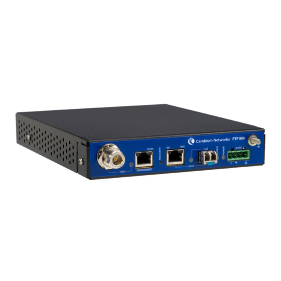
Motorola PTP 800 User Manual (379 pages)
Licensed Ethernet Microwave
Brand:
Motorola
| Category:
Microwave Oven
| Size: 2.77 MB
Table of Contents
Important Safety Information
3
Power Lines
3
Working at Heights
3
Grounding and Protective Earth
3
Electrical Safety
4
Primary Disconnect Device
4
External Cables
4
Thermal Safety
4
Table of Contents
5
About this User Guide
23
Revision History
24
Version Information
24
General Information
25
Purpose
25
Cross References
25
Text Conventions
26
Contacting Motorola
27
Feedback
27
Motorola Point-To-Point
27
Wireless Broadband Technical Support Telephone Numbers
27
Reporting Problems
29
Repair and Service
29
Warranty
29
Security Advice
31
Warnings, Cautions, and Notes
32
Warnings
32
Cautions
32
Notes
32
Caring for the Environment
33
In EU Countries
33
In Non-EU Countries
33
Licensing Requirements
34
Operating License
34
Motorola License Agreement
34
Chapter 1 Product Description
35
Overview
36
Key Features
36
Typical Users
37
Typical Applications
37
Product Variants
38
System Components
38
Table 1-1 PTP 800 Product Variants
38
Compact Modem Unit (CMU)
39
Figure 1-1 PTP 800 CMU
39
Figure 1-2 CMU Front Panel
40
Front Panel
40
Table 1-2 CMU Front Panel Interfaces
40
Table 1-3 CMU Indicator Leds
43
Outdoor Unit (ODU)
44
Figure 1-3 ODU
44
Features of the ODU
45
Figure 1-4 ODU (Front, Side and Rear View)
45
Table 1-4 ODU Components
46
Antenna and Antenna Accessories
48
Antenna
48
Figure 1-5 Typical PTP 800 Antenna (Motorola Direct Mount Interface)
48
Figure 1-6 Direct Mount Mechanical Interface
49
Figure 1-7 ODU Clipped Onto Direct Mount Mechanical Interface
49
Figure 1-8 Remote Mount Antenna Waveguide Interface
50
Remote Mount Kits
51
Figure 1-9 Remote Mount Kit Showing the Waveguide Interface
51
ODU Coupler Mounting Kit
52
Figure 1-10 Remote Mount Kit Showing the ODU Interface
52
Figure 1-11 ODU Coupler Mounting Kit
53
Figure 1-12 Two Odus and Antenna Mounted on a Coupler
53
Grounding and Lightning Protection
54
Power Supply
55
AC to DC Converter
55
Figure 1-13 AC to DC Converter
55
Wireless Operation
56
Channel Bandwidth
56
Modulation Modes
56
Adaptive Coding and Modulation
57
Wireless Link Capacity
57
Automatic Transmitter Power Control
57
Maximum Transmit Power
58
Security
58
Ethernet Bridging
59
Customer Network
59
Management Network
60
Protocol Model
63
Figure 1-14 Forwarding Behavior in Out-Of-Band Local Management Mode
63
Figure 1-15 Forwarding Behavior in Out-Of-Band Management Mode
63
Figure 1-16 Protocol Layers between Ethernet and Wireless Interfaces
64
Figure 1-17 Protocol Layers between External Interfaces and the Management Agent
64
System Management
65
Management Agent
65
Web Interface
65
Installation Wizard
65
Configuration Pages
66
Snmp
66
Email Alerts
67
Software Upgrade
68
Recovery Mode
68
Security
69
Capacity Upgrades
70
Table 1-5 Single-Step Capacity Upgrades
70
Table 1-6 Step-By-Step Capacity Upgrades
71
Chapter 2 Planning Considerations
73
Link Planning
74
Process
74
Site Selection
74
PTP Linkplanner
75
Figure 2-1 Linkplanner Profile View
76
Figure 2-2 Linkplanner Configuration and Performance Details
76
Figure 2-3 Linkplanner Bill of Materials View
77
Grounding and Lightning Protection
78
Standards
78
Lightning Protection Zones
78
General Protection Requirements
79
Figure 2-4 Rolling Sphere Method to Determine the Lightning Protection Zones
79
Specific Requirements for the ODU
80
Protection Requirements for a Mast or Tower Installation
81
Protection Requirements for the ODU on a High Rise Building
82
Figure 2-5 Grounding and Lightning Protection on Mast or Tower
82
Figure 2-6 Grounding and Lightning Protection on Building
83
Figure 2-7 Grounding in a High Rise Building - Building Steel Not Available
84
Figure 2-8 Grounding in a High Rise Building - Building Steel Available
85
Figure 2-9 Grounding and Lightning Protection Inside High Building
86
Power Supply Considerations
87
Figure 2-10 Alternative Supply Arrangements
87
Data Network Planning
88
Management Mode
88
VLAN Membership
88
Priority for Management Traffic
89
IP Interface
89
Quality of Service for Bridged Ethernet Traffic
89
Fast Ethernet Port Shutdown
90
Chapter 3 Legal Information
91
Motorola Inc. End User License Agreement
92
Definitions
92
Grant of License
92
Conditions of Use
93
Title and Restrictions
94
Confidentiality
94
Right to Use Motorola's Name
95
Transfer
95
Updates
95
Maintenance
95
Disclaimer
96
Limitation of Liability
96
U.S. Government
97
Term of License
97
Governing Law
97
Assignment
97
Survival of Provisions
98
Entire Agreement
98
Third Party Software
98
Hardware Warranty
103
Limit of Liability
104
Chapter 4 Reference Information
106
CMU Specifications
106
Dimensions and Weight
106
Environmental
106
Table 4-1 CMU Physical Specifications
106
Table 4-2 CMU Environmental Specifications
106
Electrical
107
Table 4-3 CMU Electrical Specifications
107
ODU Specifications
108
Dimensions and Weight
108
Environmental
108
RSSI Output
108
ODU Specifications (Lower 6 Ghz)
108
Table 4-4 ODU Physical Specifications
108
Table 4-5 ODU Environmental Specifications
108
ODU Specifications (7 Ghz)
109
Table 4-6 ODU Specifications - Main Frequency Lower 6 Ghz
109
Table 4-7 ODU Specifications - Main Frequency 7 Ghz
109
ODU Specifications (11 Ghz)
112
Table 4-8 ODU Specifications - Main Frequency 11 Ghz
112
ODU Specifications (18 Ghz)
113
Table 4-9 ODU Specifications - Main Frequency 18 Ghz
113
ODU Specifications (23 Ghz)
114
Table 4-10 ODU Specifications - Main Frequency 23 Ghz
114
ODU Specifications (26 Ghz)
115
ODU Specifications (38 Ghz)
115
Table 4-11 ODU Specifications - Main Frequency 26 Ghz
115
Table 4-12 ODU Specifications - Main Frequency 38 Ghz
115
Antenna Wind Velocity Limits
117
Antenna Specifications (Lower 6 Ghz)
117
Antenna Specifications (7 Ghz)
118
Table 4-13 Antenna Specifications for Lower 6 Ghz - Single Polarization
118
Table 4-14 Antenna Specifications for Lower 6 Ghz - Dual Polarization
118
Table 4-15 Antenna Specifications for 7 Ghz - Single Polarization
119
Antenna Specifications (7 Ghz)
119
Table 4-16 Antenna Specifications for 7 Ghz - Dual Polarization
120
Antenna Specifications (11 Ghz)
121
Table 4-17 Antenna Specifications for 11 Ghz - Single Polarization
121
Table 4-18 Antenna Specifications for 11 Ghz - Dual Polarization
122
Antenna Specifications (18 Ghz)
123
Table 4-19 Antenna Specifications for 18 Ghz - Single Polarization
123
Table 4-20 Antenna Specifications for 18 Ghz -Dual Polarization
123
Antenna Specifications (23 Ghz)
124
Table 4-21 Antenna Specifications for 23 Ghz - Single Polarization
124
Table 4-22 Antenna Specifications for 23 Ghz - Dual Polarization
124
Antenna Specifications (26 Ghz)
125
Table 4-23 Antenna Specifications for 26 Ghz - Single Polarization
125
Table 4-24 Antenna Specifications for 26 Ghz - Dual Polarization
125
Antenna Specifications (38 Ghz)
126
Table 4-25 Antenna Specifications for 26 Ghz - Single Polarization
126
Table 4-26 Antenna Specifications for 38 Ghz - Dual Polarization
126
Flexible Waveguide Specifications
127
Waveguide Flanges
127
Figure 4-1 Locations of Waveguide Flanges
127
Table 4-27 Antenna, Transition, Waveguide and RMK Flanges
128
Figure 4-2 Waveguide Flanges - 6 Ghz
129
Figure 4-3 Waveguide Flanges - 7 to 38 Ghz
130
Figure 4-4 Waveguide Flanges - 11 Ghz Tapered Transition
131
Table 4-28 Torque Value in Nm (Lb Ft) for each Fastener Size
131
Flexible Waveguide Specifications (Lower 6 Ghz)
132
Flexible Waveguide Specifications (7 Ghz)
132
Table 4-29 Flexible Waveguide Specifications - Lower 6 Ghz
132
Table 4-30 Flexible Waveguide Specifications - 7 Ghz
132
Flexible Waveguide Specifications (11 Ghz)
133
Flexible Waveguide Specifications (18, 23 and 26 Ghz)
133
Table 4-31 Flexible Waveguide Specifications - 11 Ghz
133
Table 4-32 Flexible Waveguide Specifications - 18, 23 and 26 Ghz
133
Flexible Waveguide Specifications (38 Ghz)
134
Flexible Waveguide Accessory Specifications
134
Table 4-33 Flexible Waveguide Specifications - 38 Ghz
134
Table 4-34 Flexible Waveguide Accessory Specifications
134
Other Component Specifications
135
AC to DC Converter Specifications
135
Table 4-35 AC to DC Converter Specifications
135
Table 4-36 Mains Leads for the AC to DC Converter
136
Table 4-37 Alternative DC Connectors
136
LPU and Cable Specifications
137
CMU Accessory Specifications
137
Table 4-38 Specifications of Lpus and if Cable Components
137
Table 4-39 CMU Accessory Specifications
137
ODU Accessory Specifications
138
Table 4-40 ODU Remote Mount Kit Specifications
138
Table 4-41 ODU Coupler Mounting Kit Specifications
138
Antenna Accessory Specifications
139
Table 4-42 Antenna Accessory Specifications
139
Wireless Operation
140
General Wireless Specifications
140
Table 4-43 General Wireless Specifications
140
Frequency Bands and Channel Separation
141
Table 4-44 ETSI Band Plan
141
Table 4-45 FCC Band Plan
141
Table 4-46 Brazil Band Plan
142
Capacity, Transmit Power and Sensitivity
143
Table 4-47 Lower 6 Ghz FCC and Canada with 10 Mhz Bandwidth
144
Table 4-48 Lower 6 Ghz FCC and Canada with 30 Mhz Bandwidth
144
Table 4-49 Lower 6 Ghz ETSI with 29.65 Mhz Channel Separation
145
Table 4-50 7 Ghz ETSI with 7 Mhz Channel Separation
145
Table 4-51 7 Ghz ETSI with 14 Mhz Channel Separation
146
Table 4-52 7 Ghz ETSI with 28 Mhz Channel Separation
146
Table 4-53 11 Ghz FCC and Canada with 10 Mhz Bandwidth
147
Table 4-54 11 Ghz FCC and Canada with 30 Mhz Bandwidth
147
Table 4-55 11 Ghz FCC and Canada with 40 Mhz Bandwidth
148
Table 4-56 11 Ghz ETSI with 40 Mhz Channel Separation
148
Table 4-57 18 Ghz FCC and Canada with 10 Mhz Bandwidth
149
Table 4-58 18 Ghz FCC and Canada with 20 Mhz Bandwidth
149
Table 4-59 18 Ghz FCC and Canada with 30 Mhz Bandwidth
150
Table 4-60 18 Ghz FCC and Canada with 40 Mhz Bandwidth
150
Table 4-61 18 Ghz FCC and Canada with 50 Mhz Bandwidth
151
Table 4-62 18 Ghz ETSI with 7 Mhz Channel Separation
151
Table 4-63 18 Ghz ETSI with 13.75 Mhz Channel Separation
152
Table 4-64 18 Ghz ETSI with 27.5 Mhz Channel Separation
152
Table 4-65 18 Ghz ETSI with 55 Mhz Channel Separation
153
Table 4-66 18 Ghz Brazil with 13.75 Mhz Channel Separation
153
Table 4-67 18 Ghz Brazil with 27.5 Mhz Channel Separation
154
Table 4-68 18 Ghz Brazil with 55 Mhz Channel Separation
154
Table 4-69 23 Ghz FCC and Canada with 10 Mhz Bandwidth
155
Table 4-70 23 Ghz FCC and Canada with 20 Mhz Bandwidth
155
Table 4-71 23 Ghz FCC and Canada with 30 Mhz Bandwidth
156
Table 4-72 23 Ghz FCC and Canada with 40 Mhz Bandwidth
156
Table 4-73 23 Ghz FCC and Canada with 50 Mhz Bandwidth
157
Table 4-74 23 Ghz ETSI with 7 Mhz Channel Separation
157
Table 4-75 23 Ghz ETSI with 14 Mhz Channel Separation
158
Table 4-76 23 Ghz ETSI with 28 Mhz Channel Separation
158
Table 4-77 23 Ghz ETSI with 56 Mhz Channel Separation
159
Table 4-78 26 Ghz ETSI with 7 Mhz Channel Separation
159
Table 4-79 26 Ghz ETSI with 14 Mhz Channel Separation
160
Table 4-80 26 Ghz ETSI with 28 Mhz Channel Separation
160
Table 4-81 26 Ghz ETSI with 56 Mhz Channel Separation
161
Table 4-82 38 Ghz ETSI with 7 Mhz Channel Separation
161
Table 4-83 38 Ghz ETSI with 14 Mhz Channel Separation
162
Table 4-84 38 Ghz ETSI with 28 Mhz Channel Separation
162
Table 4-85 38 Ghz ETSI with 56 Mhz Channel Separation
163
Data Network
164
Ethernet Interfaces
164
Table 4-86 Copper Data Port Specifications
164
Table 4-87 Fiber Data Port Specifications
164
Ethernet Bridging
165
Table 4-88 Management Port Specifications
165
Table 4-89 Ethernet Bridging Specifications
165
Safety Compliance
166
Electrical Safety Compliance
166
Table 4-90 Electrical Safety Specifications
166
Electromagnetic Compliance
167
EMC Immunity Compliance
167
Table 4-91 EMC Immunity Compliance Specifications
167
Compliance Testing
168
Notifications
169
Figure 4-5 European Union Compliance Label
170
Radiation Hazard Assessment
171
ETSI Method
171
Table 4-92 PTP 800 Minimum Separation Distances, ETSI Method
172
FCC Method
173
Table 4-93 PTP 800 Minimum Separation Distances, FCC Method
174
Chapter 5 Installation
175
Safety
176
Inventory and Tools
177
Standard PTP 800 Components
177
Table 5-1 Components of a Standard PTP 800 Installation
177
Table 5-2 Components of the Coaxial Cable Installation Assembly Kit
180
Optional Components
182
Table 5-3 Optional Components of a PTP 800 Installation
182
Tools Required
186
Table 5-4 Tools Required for PTP 800 Installation
186
Cable Connection Procedures
187
Preparing if Cables
187
Waterproofing Connectors
191
Installing the Cable Grounding Kit
194
Direct Mounting of Antenna and ODU
202
Direct Mounting of Antenna with a Single ODU
203
Direct Mounting of Antenna with Two Odus and Coupler
207
Remote Mounting of Antenna and ODU
213
Mounting ODU on Pole Using Remote Mount Kit (RMK)
214
Mounting Antenna and Flexible Waveguide
217
Mounting an 11 Ghz Antenna with Tapered Transition and Flexible Waveguide
223
Remote Mounting Antenna with Two Odus and Coupler
226
Installing the if and Ground Cables
232
Figure 5-1 Correct Orientation of Lpus
233
Connecting the ODU to the Top LPU
234
Figure 5-2 ODU and Top LPU Grounding
234
Figure 5-3 if Cable Grounding on a Mast or Tower
239
Installing and Grounding the if Cable on a Mast
239
Figure 5-4 Grounding to Round Mast Leg
241
Figure 5-5 Grounding to 'H' Section Beam
241
Figure 5-6 Grounding to 'L' Section Mast Leg
241
Figure 5-7 Grounding at Building Entry
242
Installing and Grounding the if Cable at Building Entry
242
Installing the CMU
244
Maximum Operating Ambient Temperature for the CMU
244
Operation of CMU in a Restricted Access Location
244
Mounting the CMU
245
Figure 5-8 CMU Kit Contents
245
Figure 5-9 CMU Mounted on Bench
245
Figure 5-10 CMU Mounted with Bracket
246
Figure 5-11 CMU with Rack Mount Kit and Blanking Plate
247
Figure 5-12 CMU Mounted in Rack
247
Grounding the CMU
248
Figure 5-13 Rack Mounted CMU with a Right Angled if Cable Connector
248
Figure 5-14 CMU Grounding
248
CMU Power Supply
249
Figure 5-15 CMU Ground Connector
249
Figure 5-16 Motorola AC to DC Converter
249
Testing the Installation
251
Recommended Pre-Power Tests
251
Test Equipment
251
Figure 5-17 Example of a Cable Analyzer
251
Test Preparation
252
Figure 5-18 Example of the Cable Test
252
Testing Cable Loss
253
Figure 5-19 Cable Loss Plot for a 17 Meter Cable with no ODU
254
Figure 5-20 Cable Loss Plot for a 17 Meter Cable with ODU Connected
255
Figure 5-21 Cable Loss Plot for a 100 Meter Cable with no ODU
256
Figure 5-22 Cable Loss Plot for a 100 Meter Cable with ODU Connected
256
Table 5-5 Expected Cable Loss When ODU Is Not Connected
257
Measuring Distance to Fault
258
Figure 5-23 DTF Plot for a 17 Meter Cable with no ODU
259
Figure 5-24 DTF Plot for a 17 Meter Cable with ODU Connected
260
Connecting the CMU to a PC or Workstation
261
Configure the IP Interface on the PC
261
Figure 5-25 IP Configuration on the PC
262
Figure 5-26 Internet Protocol (TCP/IP) Properties Page
262
Connecting the PC
263
Switching on the CMU
263
Figure 5-27 Setting Network Adaptor Advanced Properties
263
Open the CMU Web Interface
264
Figure 5-28 Web Interface Home Page
264
Installation Wizard
265
Step 1: Configuring Equipment Parameters
265
Figure 5-29 Step 1: Equipment Configuration Page
266
Table 5-6 Step 1: Equipment Configuration Attributes
267
Step 2: Configuring Radio License Parameters
269
Figure 5-30 Step 2: Radio License Configuration Page (Fixed Modulation)
269
Figure 5-31 Step 2: Radio License Configuration Page (FCC Adaptive Modulation)
270
Figure 5-32 Step 2: Radio License Configuration Page (ETSI Adaptive Modulation)
270
Table 5-7 Step 2: Radio License Configuration Attributes
271
Step 3: Configuring Wireless Parameters
272
Figure 5-33 Step 3: Wireless Configuration Page
272
Figure 5-34 Step 3: Wireless Configuration Page (ETSI Adaptive Modulation)
272
Step 4: Confirming Installation Configuration
273
Table 5-8 Step 3: Wireless Configuration Attributes
273
Figure 5-35 Step 4: Confirm Installation Configuration Page
274
Step 5: Starting Antenna Alignment
275
Figure 5-36 Step 5: Start Antenna Alignment Page
275
Step 6: Aligning Antennas
276
Figure 5-37 Step 6: Configuration Complete Page (Step 5 Cancelled)
276
Figure 5-38 Step 6: Antenna Alignment Page (Searching for Link)
279
Figure 5-39 Step 6: Antenna Alignment Page (Link Established)
279
Figure 5-40 Alignment Abandoned
280
Figure 5-41 Testing ODU Voltage Output
280
Figure 5-42 Antenna Alignment Mechanism
281
Figure 5-43 Relationship between Voltage and Alignment (Degrees)
281
Step 7: Completing Installation
282
Figure 5-44 Alignment Voltage and Lobe Rings
282
Figure 5-45 Step 7: Installation Complete Page
282
Connecting the CMU to the Network
283
Update Security and Capacity Capabilities
283
Configure Security
283
Configure Remote Management Using SNMP or SMTP
283
Set the Real-Time Clock
284
Configure Quality of Service for Bridged Ethernet Traffic
284
LAN Configuration
284
Connect to the Network
285
Alternative Approaches
287
Update Capabilities before Installation
287
Configure Security before Installation
287
LAN Configuration before Installation
287
Partial Installation with ODU Connected
288
Partial Installation with ODU Disconnected
288
Figure 5-46 Step 1: Enter Equipment Details (ODU Disconnected)
289
Figure 5-47 Step 5: Configuration Complete Page (ODU Disconnected)
289
Chapter 6 Operation
292
Web-Based Management
292
Overview
292
Figure 6-1 Web Interface
292
Menu
293
System Summary
293
Figure 6-2 System Summary Page
293
Table 6-1 System Summary Attributes
294
System Status
295
Figure 6-3 System Status Page
295
Table 6-2 ODU Status Attribute Values
296
Table 6-3 Transmitter Status Attribute Values
297
Table 6-4 Data Port Status Attribute Values
297
Table 6-5 Management Port Status Attribute Values
297
Table 6-6 Wireless Link Status Attribute Values
297
Table 6-7 Transmit Modulation Selection Detail Attribute Values
298
System Administration
299
Figure 6-4 System Administration Login Page
299
Figure 6-5 System Administration Menu (with All Submenus Opened)
300
Configuring the Wireless Interface
301
Enabling Wireless Transmission
301
Disabling Wireless Transmission
301
Figure 6-6 System Configuration Page (Partial View) When Transmitter Is Muted
301
Figure 6-7 System Configuration Page
302
Updating Site Name
303
Reviewing and Updating System Configuration
304
Table 6-8 System Configuration Attributes
304
Configuring Quality of Service
306
Figure 6-8 Bridge Configuration Page
306
Table 6-9 Quality of Service Attributes
307
Configuring the IP and Ethernet Interfaces
308
Configuring the IP Interface and Management Mode
308
Figure 6-9 LAN Configuration Page with VLAN Disabled
309
Figure 6-10 LAN Configuration Page with VLAN Enabled
310
Table 6-10 IP Interface Attributes
311
Figure 6-11 Confirm LAN Configuration
313
Configuring the Ethernet Ports
314
Table 6-11 Ethernet (Management and Data) Port Attributes
314
Configuring Bridged Ethernet Traffic
316
Table 6-12 Bridged Ethernet Traffic Attributes
316
Checking Capability Summary
318
Figure 6-12 Software License Key Page
318
Upgrading the PTP 800
318
Using Access Keys to Generate a New License Key
319
Table 6-13 Capability Summary Attributes
319
Entering a License Key
320
Figure 6-13 Reboot Wireless Unit Dialog
320
Figure 6-14 Reboot Confirmation Dialog
320
Saving and Restoring System Configuration
321
Figure 6-15 Save & Restore Configuration Page
322
Upgrading PTP 800 Software
324
Figure 6-16 Software Upgrade Page
325
Figure 6-17 Software Upgrade Confirmation Page
325
Figure 6-18 Software Upgrade Complete Page
326
Managing Security
327
Changing Administrator Password
327
Figure 6-19 Change System Administrator Password Page
327
Enabling AES Encryption
328
Table 6-14 Change System Administrator Password Attributes
328
Figure 6-20 Configuration Change Reboot Dialog
329
Table 6-15 AES Encryption Attributes
329
Disabling AES Encryption
330
Changing AES Encryption Keys
331
Changing the Log-Out Timer
332
Figure 6-21 Web Page Properties Page
332
Protecting Access to the Summary and Status Pages
333
Managing Faults
334
Configuring the CMU to Generate SNMP Notifications
334
Figure 6-22 Remote Management Page
335
Table 6-16 Remote Management Page SNMP Attributes
336
Configuring Generation of Diagnostic Alarms
337
Figure 6-23 Diagnostic Alarms Page
337
Table 6-17 Diagnostic Alarms
338
Configuring the CMU to Generate Email Messages
339
Table 6-18 Remote Management Page SMTP Attributes
340
Rebooting the CMU
341
Figure 6-24 Reboot Wireless Unit Page
341
Setting the Real-Time Clock
342
Figure 6-25 Clock Section of Remote Management Page (SNTP Disabled)
342
Table 6-19 Manual Clock Attributes
343
Figure 6-26 Clock Section of Remote Management Page (SNTP Enabled)
344
Table 6-20 SNTP Clock Attributes
344
Managing Performance
345
Checking System Statistics and Counters
345
Figure 6-27 System Statistics and Counters Page
346
Table 6-21 System Statistics and Counters Attributes
347
Resetting System Statistics and Counters
349
Using the Diagnostics Plotter
349
Figure 6-28 Diagnostics Plotter Page
350
Downloading Diagnostic Data
351
Changing the Diagnostics Refresh Period
352
Figure 6-29 Generate Downloadable Diagnostics Page
352
Maintaining the System
353
Chapter 7 Troubleshooting
355
Connecting to the Web Management Interface
356
Check the CMU Power Indicator
356
Check the DC Supply to the CMU
356
Table 7-1 CMU Power Indicator Checks
356
Check the CMU Status Indicator
357
Table 7-3 CMU Status Indicator Checks
357
CMU out of Service
358
Check the Management Port Ethernet Connection
358
Table 7-4 Management Port Indicator Checks
358
Check the Copper Data Port Ethernet Connection
359
Table 7-5 Copper Data Port Indicator Checks
359
Check the Fiber Data Port Ethernet Connection
360
Table 7-6 Fiber Data Port Indicator Checks
360
Check IP Network Connection
361
Check Browser Settings
362
Table 7-7 Ping Response Checks
362
Installing the Link
363
Connect to the Web Management Interface
363
Check ODU Status
363
Transmitter Status
363
Table 7-8 ODU Status Checks
363
Antenna Alignment
364
Table 7-9 Transmitter Status Checks
364
Check Transmit and Receive Frequencies
365
Check Waveguide and Antennas
365
Check Link Status
365
Table 7-10 Link Status Checks
365
Recovering the CMU
366
Entering Recovery Mode
366
Selecting Recovery Option
368
Figure 7-1 Recovery Mode Warning Page
368
Figure 7-2 Recovery Options Page
369
Upgrading the Software Image
370
Figure 7-3 Recovery Software Upgrade Confirmation Page
370
Resetting IP and Ethernet Configuration to Factory Defaults
371
Figure 7-4 Recovery Software Upgrade Complete Page
371
Erasing Configuration
372
Figure 7-5 Reset Configuration Dialog
372
Zeroizing Security Parameters
373
Figure 7-6 Erase Configuration Dialog
373
Figure 7-7 Zeroize Security Parameters Dialog
373
Downgrading PTP 800 Software
374
Glossary
375
Index
377
Advertisement
Advertisement
Related Products
Motorola PTP 300 Series
Motorola PTP 500
Motorola PTP 500 Series
Motorola PTP 49200
Motorola PTP 25600
Motorola PTP 59600
Motorola PTP 54200
Motorola PTP 58600 Lite
Motorola PTP 54500 Lite
Motorola PTP 49400
Motorola Categories
Cell Phone
Two-Way Radio
Baby Monitor
Cordless Telephone
Radio
More Motorola Manuals
Login
Sign In
OR
Sign in with Facebook
Sign in with Google
Upload manual
Upload from disk
Upload from URL