Lenovo ThinkSystem SR850 Maintenance Manual
Hide thumbs
Also See for ThinkSystem SR850:
- Reference (226 pages) ,
- Maintenance manual (200 pages) ,
- Setup manual (156 pages)
Table of Contents
Advertisement
Quick Links
Advertisement
Table of Contents

Related Manuals for Lenovo ThinkSystem SR850


Summary of Contents for Lenovo ThinkSystem SR850
- Page 1 ThinkSystem SR850 Maintenance Manual Machine Type: 7X18 and 7X19...
- Page 2 Before using this information and the product it supports, be sure to read and understand the safety information and the safety instructions, which are available at: http://thinksystem.lenovofiles.com/help/topic/safety_documentation/pdf_files.html In addition, be sure that you are familiar with the terms and conditions of the Lenovo warranty for your server, which can be found at: http://datacentersupport.lenovo.com/warrantylookup Second Edition (August 2017) ©...
-
Page 3: Table Of Contents
....111 CMOS battery - CR2032 replacement ..Remove the CMOS battery - CR2032 ..Security bezel replacement ..114 © Copyright Lenovo 2017... - Page 4 ....142 Index ....169 Troubleshooting by symptom ..143 ThinkSystem SR850 Maintenance Manual...
-
Page 5: Safety
Avant d'installer ce produit, lisez les consignes de sécurité. Vor der Installation dieses Produkts die Sicherheitshinweise lesen. Prima di installare questo prodotto, leggere le Informazioni sulla Sicurezza. Les sikkerhetsinformasjonen (Safety Information) før du installerer dette produktet. © Copyright Lenovo 2017... -
Page 6: Safety Inspection Checklist
Caution: This equipment must be installed by trained service personnel, as defined by the NEC and IEC 60950-1, Second Edition, the standard for Safety of Information Technology Equipment. Lenovo assumes you are qualified in the servicing of equipment and trained in recognizing hazards in products with hazardous energy levels. - Page 7 Click the Power tab to see all line cords. • Make sure that the insulation is not frayed or worn. 3. Check for any obvious non-Lenovo alterations. Use good judgment as to the safety of any non-Lenovo alterations. 4. Check inside the server for any obvious unsafe conditions, such as metal filings, contamination, water or other liquid, or signs of fire or smoke damage.
- Page 8 ThinkSystem SR850 Maintenance Manual...
-
Page 9: Chapter 1. Introduction
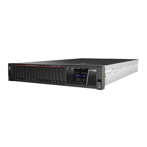
Chapter 1. Introduction The ThinkSystem SR850 is a 2U rack server designed for high-volume network transaction processing. This high-performance, multi-core server is ideally suited for networking environments that require superior processor performance, input/output (I/O) flexibility, and high manageability. Figure 1. ThinkSystem SR850 The server comes with a limited warranty. - Page 10 • Slot 8: PCI Express 3.0 x8 • Slot 9: PCI Express 3.0 x8 • Slot 10: PCI Express 3.0 x8 (supports RAID adapters for SATA/SAS drives) • Slot 11: PCI Express 3.0 x16 (supports PCIe switch card) ThinkSystem SR850 Maintenance Manual...
- Page 11 Table 1. Specifications, Type 7X18 and 7X19 (continued) Integrated functions • Lenovo XClarity Controller (XCC), which provides service processor control and monitoring functions, video controller, and remote keyboard, video, mouse, and remote drive capabilities. • One system-management RJ-45 connector on the rear to connect to a systems- management network.
-
Page 12: Firmware Updates
CPU. • Out-of-band update. The installation or update is performed by the Lenovo XClarity Controller collecting the update and then directing the update to the target subsystem or device. Out-of-band updates have no dependency on an operating system executing on the core CPU. - Page 13 Hat Enterprise Linux (RHEL) and SUSE Linux Enterprise Server (SLES) operating system distributions. Machine-type-specific firmware-only UXSPs are also available. See the following table to determine the best Lenovo tool to use for installing and setting up the firmware: Out-of- Off-...
- Page 14 Additional information about using Lenovo XClarity Provisioning Manager to update firmware is available http://sysmgt.lenovofiles.com/help/topic/LXPM/platform_update.html • Lenovo XClarity Controller If you need to install a specific update, you can use the Lenovo XClarity Controller interface for a specific server. Notes: – To perform an in-band update through Windows or Linux, the operating system driver must be installed and the Ethernet-over-USB (sometimes called LAN over USB) interface must be enabled.
-
Page 15: Configuring The Lan Over Usb Interface Manually
Return to the Device Manager. Lenovo USB Remote NDIS Network Device appears under Network Adapters. Step 9. Use the Lenovo XClarity Controller interface to view or set the IP address for the LAN adapter. Additional information about using the Lenovo XClarity Controller to configure LAN over USB is available at: http://sysmgt.lenovofiles.com/help/topic/com.lenovo.systems.management.xcc.doc/NN1ia_c_... -
Page 16: Tech Tips
Power off the server The server remains in a standby state when it is connected to a power source, allowing the Lenovo XClarity Controller to respond to remote power-on requests. To remove all power from the server (power status LED off), you must disconnect all power cables. -
Page 17: Chapter 2. Server Components
Use the information in this section to learn about each of the components associated with your server. Identifying your server When you contact Lenovo for help, the machine type, model, and serial number information helps support technicians to identify your server and provide faster service. - Page 18 Identification button/LED (blue) Drive status LED (yellow) System error LED (yellow) Pull-out information tab Front operator panel with optional pull-out LCD display USB 1 (USB 2.0 with Lenovo XClarity Controller Rack release latches management) 2.5-inch drive bays USB 2 Power button/LED (green) VGA connector (optional): Connect a monitor to this connector.
- Page 19 Controller mobile application. When a mobile device is connected to this USB port, an Ethernet over USB connection is established between the mobile application running on the device and the XClarity Controller. Select Network in BMC Configuration to view or modify USB 2.0 with Lenovo XClarity Controller management settings. Four types of settings are available: –...
-
Page 20: Front Operator Panel
Identification button/LED (blue) Use this blue LED to visually locate the server among other servers. This LED is also used as a presence detection button. You can use Lenovo XClarity Administrator to light this LED remotely. System error LED (yellow) When this yellow LED is lit, it indicates that a system error has occurred. - Page 21 Figure 6. Front operator panel and LCD display The LCD system information display panel attached to the front of the server allows quick access to system status, firmware, network, and health information. Figure 7. System information and control of the front operator panel Table 4.
- Page 22 Following is the list of options available on the front operator panel. Switch between an option and the subordinate information entries with Select (√) button, and switch among options or information entries with Scroll up (▼) and Scroll down (▲) buttons. ThinkSystem SR850 Maintenance Manual...
- Page 23 Table 6. Options available on the front operator panel Option Description System error System error provides the total number of errors the system encountered, and the description of these errors. The information is displayed as following: System Has Encountered X Errors Whereas X is the total number of system errors encountered.
- Page 24 Switch between CPU1/2 and CPU3/4 with scroll up and down buttons. • AC input voltage is displayed as following: PS1 AC Voltage: YYY V PS2 AC Voltage: YYY V • Estimated power consumption is displayed as following: Sytem Power: ZZ W Whereas ThinkSystem SR850 Maintenance Manual...
-
Page 25: Rear View
Table 6. Options available on the front operator panel (continued) • XX is the temperature. • YYY is the AC voltage. • ZZ is the wattage. Actions Actions provides the following available actions, which come in effect by pressing and holding on the select button for three seconds: •... - Page 26 – Slot 4: Not available – Slot 5: Customized slot for ML2 adapter M.2 backplane (slot 6): Install M.2 backplane to this slot. See “M.2 drive and backplane replacement” on page 74 for more details. LOM adapter (slot 7): ThinkSystem SR850 Maintenance Manual...
- Page 27 Insert LOM adapter into this slot. (see “System-board connectors” on page 21 for the location of the LOM adapter slot on the system board and “LOM adapter replacement” on page 71 for information about the installation of the LOM adapter. AC power LED: Each hot-swap power supply comes with an ac power LED and a dc power LED.
- Page 28 Use this connector to manage the server, by using a dedicated management network. If you use this connector, the Lenovo XClarity Controller cannot be accessed directly from the production network. A dedicated management network provides additional security by physically separating the management network traffic from the production network.
-
Page 29: System-Board Connectors
Table 8. System-board connectors PCIe slot 11, 10, 9, 8 Front operator panel connector PCIe slot 7 (LOM adapter) USB 1 (USB 2.0 with Lenovo XClarity Controller management) Backplane connector 2 PCIe slot 6 (M.2 backplane) PCIe slot 3-5 (PCIe riser-card) -
Page 30: Switches, Jumpers, And Buttons
The following table describes the functions of the SW613 switch block on the system board. Table 10. System-board SW13 switch block descriptions Default position Switch number Host TPM Physical Presence Host TPM Physical Presence disable enable ThinkSystem SR850 Maintenance Manual... -
Page 31: System-Board Leds
You can also use it to force a blue-screen memory dump (use this button only when you are directed to do so by Lenovo Support). System-board LEDs Use this information to locate the system-board LEDs. -
Page 32: Optional Processor And Memory Expansion Tray
Optional processor and memory expansion tray Use this information to locate the connectors and LEDs on the optional processor and memory expansion tray. The following illustrations show the connectors and LEDs on the processor and memory expansion tray. ThinkSystem SR850 Maintenance Manual... - Page 33 Figure 14. Optional processor and memory expansion tray Table 13. Components on the optional processor and memory expansion tray Power supply 2 connector DIMM slot 31-42 Tray handle Processor 3 DIMM slot 43-48 DIMM slot 25-30 Processor 4 Figure 15. LEDs on the optional processor and memory expansion tray Table 14.
- Page 34 Figure 16. Connectors on the optional processor and memory expansion tray Table 15. Connectors on the optional processor and memory expansion tray NVMe signal cable connector 0-1 NVMe signal cable connector 2-3 ThinkSystem SR850 Maintenance Manual...
-
Page 35: Pcie Riser-Cards
PCIe riser-cards Use this information to locate the connectors on the optional PCIe riser-cards. x8/x8/x8 PCIe FH Riser Assembly Figure 17. x8/x8/x8 PCIe FH Riser Assembly Table 16. Components of x8/x8/x8 PCIe FH Riser Assembly PCIe full-height riser cage PCI Express 3.0 x8 (slot 4) PCI Express 3.0 x8 (slot 3) PCI Express 3.0 x8 (slot 5) x8/x8/x8ML2 PCIe FH Riser Assembly... -
Page 36: 2.5-Inch Drive Backplanes
Power/configuration cable connector 2.5-inch SATA/SAS 8-bay backplane comes with: • Eight SATA/SAS drive connectors with bay numbers of 0-7 or 8-15, depending on the location installed. • One power/configuration connector • Two SATA/SAS connectors (0, 1) ThinkSystem SR850 Maintenance Manual... -
Page 37: Raid Adapters
2.5-inch AnyBay (SATA/SAS/NVMe) 8-bay backplane Figure 21. 2.5-inch AnyBay (SATA/SAS/NVMe) 8-bay backplane Table 20. Connectors on 2.5-inch AnyBay (SATA/SAS/NVMe) 8-bay backplane NVMe connector 3 SATA/SAS connector 1 NVMe connector 2 SATA/SAS connector 0 NVMe connector 1 Power/configuration cable connector NVMe connector 0 Cable numbering labels 2.5-inch AnyBay (SATA/SAS/NVMe) 8-bay backplane comes with: •... -
Page 38: Internal Cable Routing
– Four processors installed • “Connecting signal cables to two backplanes” on page 36 – “8-bay backplane + 8-bay backplane” on page 36 – “8-bay backplane + AnyBay backplane” on page 38 – Two processors installed ThinkSystem SR850 Maintenance Manual... - Page 39 – Four processors installed – “AnyBay backplane + AnyBay backplane” on page 42 – Two processors installed – Four processors installed Important: 1. Make sure all the signal cables go through the cable guides. Figure 25. Cable guide locations 2. Connect the direct NVMe signal cables to the NVMe connectors on the processor and memory expansion tray.
- Page 40 • 2.5-inch SATA/SAS 8-bay backplane (referred to as “8-bay backplane”) • 2.5-inch AnyBay 8-bay backplane (referred to as “AnyBay backplane”) Connecting signal cables to one backplane When there is one backplane installed, see the following illustrations for cable routing. ThinkSystem SR850 Maintenance Manual...
- Page 41 One 8-bay backplane Figure 28. Cable routing, 8-bay backplane Table 25. Cables and adapters for routing SATA/SAS RAID adapter (8i) SATA/SAS signal cables (720 mm) Chapter 2 Server components...
- Page 42 Figure 29. Cable routing, AnyBay backplane with two processors installed Table 26. Cables and adapters for routing PCIe switch card NVMe signal cables for PCIe switch card SATA/SAS RAID adapter (8i) SATA/SAS signal cables (720 mm) ThinkSystem SR850 Maintenance Manual...
- Page 43 Four processors installed Figure 30. Cable routing, AnyBay backplane Note: Install the processor and memory expansion tray before connecting the signal cables to NVMe connector on the expansion tray. Table 27. Cables and adapters for routing SATA/SAS RAID adapter (8i) Direct NVMe signal cables for processor and memory expansion tray NVMe connectors on the processor and memory...
- Page 44 1. With SATA/SAS RAID adapter (16i) Figure 31. Cable routing, 8-bay backplane + 8-bay backplane Table 28. Cables and adapters for routing SATA/SAS RAID adapter (16i) SATA/SAS signal cables (720 mm) SATA/SAS signal cables (900 mm) ThinkSystem SR850 Maintenance Manual...
- Page 45 2. With SATA/SAS RAID adapter (8i) Figure 32. Cable routing, 8-bay backplane + 8-bay backplane Table 29. Cables and adapters for routing SATA/SAS RAID adapter (8i) SATA/SAS signal cables (720 mm) SATA/SAS RAID adapter (8i) SATA/SAS signal cables (720 mm) Chapter 2 Server components...
- Page 46 Figure 33. Cable routing, 8-bay backplane + AnyBay backplane Table 30. Cables and adapters for routing SATA/SAS RAID adapter (16i) SATA/SAS signal cables (720 mm) PCIe switch card SATA/SAS signal cables (900 mm) NVMe signal cables for PCIe switch card ThinkSystem SR850 Maintenance Manual...
- Page 47 2. With SATA/SAS RAID adapter (8i) Figure 34. Cable routing, 8-bay backplane + AnyBay backplane Table 31. Cables and adapters for routing SATA/SAS RAID adapter (8i) SATA/SAS signal cables (720 mm) SATA/SAS RAID adapter (8i) NVMe signal cables for PCIe switch card PCIe switch card SATA/SAS signal cables (720 mm) Chapter 2...
- Page 48 Table 32. Cables and adapters for routing SATA/SAS RAID adapter (16i) SATA/SAS signal cables (720 mm) NVMe connectors on the processor and memory SATA/SAS signal cables (900 mm) expansion tray Direct NVMe signal cables for processor and memory expansion tray ThinkSystem SR850 Maintenance Manual...
- Page 49 2. With SATA/SAS RAID adapter (8i) Figure 36. Cable routing, 8-bay backplane + AnyBay backplane Table 33. Cables and adapters for routing SATA/SAS RAID adapter (8i) Direct NVMe signal cables for processor and memory expansion tray NVMe connectors on the processor and memory SATA/SAS signal cables (720 mm) expansion tray SATA/SAS RAID adapter (8i)
- Page 50 NVMe signal cables for PCIe switch card SATA/SAS RAID adapter (16i) NVMe signal cables for PCIe switch card PCIe switch card SATA/SAS signal cables (720 mm) SATA/SAS signal cables (900 mm) 2. With SATA/SAS RAID adapter (8i) ThinkSystem SR850 Maintenance Manual...
- Page 51 Figure 38. Cable routing, AnyBay backplane + AnyBay backplane Table 35. Cables and adapters for routing PCIe switch card SATA/SAS signal cables (720 mm) SATA/SAS RAID adapter (8i) NVMe signal cables for PCIe switch card SATA/SAS RAID adapter (8i) NVMe signal cables for PCIe switch card PCIe switch card SATA/SAS signal cables (720 mm) Chapter 2...
- Page 52 SATA/SAS signal cables (720 mm) NVMe connectors on the processor and memory NVMe signal cables for PCIe switch card expansion tray Direct NVMe signal cables for processor and memory expansion tray 2. With SATA/SAS RAID adapter (8i) ThinkSystem SR850 Maintenance Manual...
-
Page 53: Parts List
Use the parts list to identify each of the components that are available for your server. For more information about ordering the parts shown in Figure 41 “Server components” on page 46: 1. Go to http://datacentersupport.lenovo.com and navigate to the support page for your server. 2. Click Parts & Accessories ➙ Parts Lookup. - Page 54 Figure 41. Server components The parts listed in the following table are identified as one of the following: ThinkSystem SR850 Maintenance Manual...
- Page 55 Tier 1 CRU at your request with no service agreement, you will be charged for the installation. • Tier 2 customer replaceable unit: You may install a Tier 2 CRU yourself or request Lenovo to install it, at no additional charge, under the type of warranty service that is designated for your server.
- Page 56 For more information about ordering parts: 1. Go to http://datacentersupport.lenovo.com and click Parts & Accessories. 2. Click Parts Lookup. 3. Enter either the serial number or the machine type model for your server to see the parts for your server.
-
Page 57: Power Cords
Several power cords are available, depending on the country and region where the server is installed. To view the power cords that are available for the server: 1. Go to: http://lesc.lenovo.com 2. In the Customize a Model pane: a. Click Select Options/Parts for a Model. - Page 58 ThinkSystem SR850 Maintenance Manual...
-
Page 59: Chapter 3. Hardware Replacement Procedures
For more information about ordering parts: 1. Go to http://datacentersupport.lenovo.com and navigate to the support page for your server. 2. Click Service Parts. 3. Enter the serial number to view a listing of parts for your server. -
Page 60: System Reliability Guidelines
Operating the server with a missing air baffle might damage the processor. • All processor sockets must contain either a socket cover or a processor with heat sink. • When more than one processor is installed, fan population rules for each server must be strictly followed. ThinkSystem SR850 Maintenance Manual... -
Page 61: Working Inside The Server With The Power On
Working inside the server with the power on You might need to keep the power on with the server cover removed to look at system information on the display panel or to replace hot-swap components. Review these guidelines before doing so. S033 CAUTION: Hazardous energy present. -
Page 62: 2.5-Inch Hot-Swap Drive And Drive Backplane Replacement
Rotate the backplane from the top toward the center of the server to disengage it from the retention latches. If you are instructed to return the component or optional device, follow all packaging instructions, and use any packaging materials for shipping that are supplied to you. ThinkSystem SR850 Maintenance Manual... -
Page 63: Install A Drive Backplane
Install a drive backplane Use this procedure to install a drive backplane. Before installing a drive backplane: 1. Read the safety information and installation guidelines (see “Safety” on page iii and “Installation Guidelines” on page 51). 2. Touch the static-protective package that contains the component to any unpainted metal surface on the server;... -
Page 64: Install A 2.5-Inch Hot-Swap Drive
• SATA/SAS solid-state drive • SATA/SAS hard-disk drive For a complete list of supported optional device for this server, see http://www.lenovo.com/serverproven/. Before installing a 2.5-inch hot-swap drive: 1. Read the safety information and installation guidelines (see “Safety” on page iii and “Installation Guidelines”... -
Page 65: Cmos Battery - Cr2032 Replacement
Step 1. If new drives are to be added, see “Install a 2.5-inch drive” in ThinkSystem SR850 Setup Guide to determine available drive bays to the new drives. Step 2. Gently rotate the release latch away to unlock the drive handle. - Page 66 S004 CAUTION: When replacing the lithium battery, use only Lenovo specified part number or an equivalent type battery recommended by the manufacturer. If your system has a module containing a lithium battery, replace it only with the same module type made by the same manufacturer. The battery contains lithium and can explode if not properly used, handled, or disposed of.
- Page 67 6. Remove the system board air baffle (see “Remove the system board air baffle and the power interposer” on page 116) or the processor and memory expansion tray and the expansion tray air baffle (see “Remove the processor and memory expansion tray” on page 110). Figure 46.
-
Page 68: Install The Cmos Battery - Cr2032
S004 CAUTION: When replacing the lithium battery, use only Lenovo specified part number or an equivalent type battery recommended by the manufacturer. If your system has a module containing a lithium battery, replace it only with the same module type made by the same manufacturer. The battery contains lithium and can explode if not properly used, handled, or disposed of. -
Page 69: Fan And Fan Cage Replacement
1. Read the safety information and installation guidelines (see “Safety” on page iii and “Installation Guidelines” on page 51). 2. Touch the static-protective package that contains the component to any unpainted metal surface on the server; then, remove it from the package and place it on a static-protective surface. 3. - Page 70 5. Remove the top cover (see “Remove the top cover” on page 130). To remove the fan cage assembly, complete the following steps: Step 1. Lift and rotate the fan cage release latches to disengage the fan cage assembly from the server. Figure 49. Fan cage assembly removal ThinkSystem SR850 Maintenance Manual...
-
Page 71: Install The Fan Cage Assembly
Step 2. Lift the fan cage assembly from the server. If you are instructed to return the component or optional device, follow all packaging instructions, and use any packaging materials for shipping that are supplied to you. Install the fan cage assembly Use this procedure to install the fan cage assembly. -
Page 72: Remove A Hot-Swap Fan
4. Remove the top cover (see “Remove the top cover” on page 130). To remove a hot-swap-fan, complete the following steps: Step 1. Pinch on the top of the fan, and press on the latch to release the fan from the connector. ThinkSystem SR850 Maintenance Manual... -
Page 73: Install A Hot-Swap Fan
Figure 51. Hot-swap fan removal Attention: When replacing a fan with power on, complete the replacement within 30 seconds to ensure proper operation. Step 2. Lift the fan out from the fan cage. If you are instructed to return the component or optional device, follow all packaging instructions, and use any packaging materials for shipping that are supplied to you. -
Page 74: Front Vga Assembly Replacement
2. Install the server in the rack. Front VGA assembly replacement Use this procedure to remove or install the front VGA assembly. Remove the front VGA assembly Use this procedure to remove the front VGA assembly. Before removing the front VGA assembly: ThinkSystem SR850 Maintenance Manual... - Page 75 1. Read the safety information and installation guidelines (see “Safety” on page iii and “Installation Guidelines” on page 51). 2. Turn off the server and peripheral devices and disconnect the power cords and all external cables (see “Power off the server” on page 8). 3.
-
Page 76: Install The Front Vga Assembly
3. Watch the procedure. A video of this procedure is available from the following links: • https://www.youtube.com/playlist?list=PLYV5R7hVcs-B2y7oAb54mfyuLrIusa_qE • http://list.youku.com/albumlist/show/id_50483449 To install the front VGA assembly, complete the following steps: ThinkSystem SR850 Maintenance Manual... - Page 77 Step 1. Remove the fan cage assembly (see “Remove the fan cage assembly” on page 61). Step 2. Route the cable into the slot. Figure 57. Front VGA assembly installation Step 3. Align the front VGA assembly with the alignment pin, and push it slightly toward the rear of the server to it to the server.
- Page 78 Figure 59. Front VGA assembly installation Step 5. Install the front VGA assembly with four screws. Figure 60. Front VGA assembly installation Step 6. Connect the front video cable to the system board. ThinkSystem SR850 Maintenance Manual...
-
Page 79: Lom Adapter Replacement
Figure 61. Front VGA assembly installation After installing front VGA assembly, complete the following steps: 1. Reinstall the fan cage (see “Install the fan cage assembly” on page 63) 2. Reinstall the top cover (see “Install the top cover” on page 131). 3. -
Page 80: Install The Lom Adapter
Following are the requirements: • 1GbE LOM adapter: maximal bandwidth of network environment is 1GB. • 10GbE LOM adapter: minimal bandwidth of network environment is 1GB. 5. Attach the mounting bracket with the two screws as illustrated. ThinkSystem SR850 Maintenance Manual... - Page 81 Figure 63. LOM adapter assembly To install the LOM adapter, complete the following steps: Step 1. Open the retention latch. Step 2. Align the LOM adapter to the connector, and push it in. Step 3. Tighten the captive thumbscrew to lock it to the system board. Figure 64.
-
Page 82: M.2 Drive And Backplane Replacement
3. If the server is installed in a rack, slide the server out on its rack slide rails to gain access to the top cover, or remove the server from the rack. 4. Remove the top cover (see “Remove the top cover” on page 130). ThinkSystem SR850 Maintenance Manual... - Page 83 5. Disconnect the USB 3.0 cable of operator panel tray assembly, and remove it vertically from the system board. Figure 66. Removing USB 3.0 connector vertically 6. Remove PCIe riser-card if necessary (see “Remove the PCIe riser-card assembly” on page 86). 7.
-
Page 84: Install The M.2 Backplane
Align the openings located at the bottom of the blue plastic supports at each end of the M.2 backplane with the guide pin on the system board and T-head pins on the hard drive cage; then, insert the backplane in the system board connector. Press down on the M.2 backplane to fully seat ThinkSystem SR850 Maintenance Manual... -
Page 85: Remove An M.2 Drive From The M.2 Backplane
Figure 69. M.2 backplane installation After installing the M.2 backplane, complete the following steps: 1. Reinstall the PCIe riser-card if necessary (see “Install the PCIe riser-card assembly” on page 88). 2. Reinstall the LOM adapter if necessary (see “Install the LOM adapter” on page 72). 3. -
Page 86: Install An M.2 Drive In The M.2 Backplane
Insert the M.2 drive at an angle (approximately 30 degrees) into the connector and rotate it until the notch catches on the lip of the retainer; then, slide the retainer forward (toward the connector) to secure the M.2 drive in the M.2 backplane. ThinkSystem SR850 Maintenance Manual... -
Page 87: Memory Module Replacement
Figure 72. M.2 drive installation Attention: When sliding the retainer forward, make sure the two nubs on the retainer enter the small holes on the M.2 backplane. Once they enter the holes, you will hear a soft “click” sound. Figure 73. M.2 drive installation with the retainers in place After installing an M.2 drive in the M.2 backplane, see “Install the M.2 backplane”... - Page 88 5. Remove the top cover (see “Remove the top cover” on page 130). 6. If you are not replacing the memory module that you removed, see the ThinkSystem SR850 Memory Population Reference for the required installation order of the remaining memory modules.
-
Page 89: Install A Memory Module
If you are instructed to return the component or optional device, follow all packaging instructions, and use any packaging materials for shipping that are supplied to you. Install a memory module Use this procedure to install a memory module. “ATTENTION: Static Sensitive Device Ground package before opening”... -
Page 90: Operator Panel Tray Assembly And Front Operator Panel Replacement
5. Remove the top cover (see “Remove the top cover” on page 130). To remove the operator panel tray assembly, complete the following steps: Step 1. Remove the fan cage assembly (see “Remove the fan cage assembly” on page 61). ThinkSystem SR850 Maintenance Manual... -
Page 91: Install The Operator Panel Tray Assembly
Step 2. Disconnect USB cables and front operator panel cable from the system board. Note: Make sure the USB 3.0 connector stays vertical when being removed from the system board. Figure 76. Removing USB 3.0 connector vertically Step 3. Remove the USB 3.0 cable from the cable guide. Step 4. - Page 92 Note: Make sure the USB 3.0 connector stays vertical when being pushed into the connector on the system board. Figure 79. Connecting USB 3.0 cable After installing the operator panel tray assembly, complete the following steps: 1. Reinstall the top cover (see “Install the top cover” on page 131). ThinkSystem SR850 Maintenance Manual...
-
Page 93: Remove The Front Operator Panel
2. Reconnect the power cords and any cables that you removed. 3. Install the server in the rack. 4. Power on the server and any peripheral devices. Remove the front operator panel Use this procedure to remove the front operator panel. With the operator panel tray assembly removed from the system (see “Remove the operator panel tray assembly”... -
Page 94: Pcie Riser-Card Assembly And Adapter Replacement
• https://www.youtube.com/playlist?list=PLYV5R7hVcs-B2y7oAb54mfyuLrIusa_qE • http://list.youku.com/albumlist/show/id_50483449 5. Remove the top cover (see “Remove the top cover” on page 130). 6. Disconnect the USB 3.0 cable of operator panel tray assembly, and remove it vertically from the system board. ThinkSystem SR850 Maintenance Manual... - Page 95 Figure 82. Removing USB 3.0 connector vertically To remove the PCIe riser-card assembly, complete the following steps: Step 1. Disconnect any cables connected to the adapter(s). Step 2. Grasp the PCIe riser-card assembly at the touch-points, and lift it out from the system board. Figure 83.
-
Page 96: Install The Pcie Riser-Card Assembly
4. Disconnect the USB 3.0 cable of operator panel tray assembly, and remove it vertically from the system board. Figure 85. Removing USB 3.0 connector vertically To install the PCIe riser-card assembly, complete the following steps: Step 1. Assemble the PCIe riser-card assembly: ThinkSystem SR850 Maintenance Manual... - Page 97 Align the bottom of the PCIe riser-card to the slot, and rotate the top to fit it into the slot on the riser-cage; then, move the PCIe riser-card slightly to fit the holes into the pins. Figure 86. PCIe riser-card assembly Install the PCIe riser-card to the riser-cage with screws.
-
Page 98: Remove An Adapter
5. Remove the top cover (see “Remove the top cover” on page 130). To remove an adapter from the system board, complete the following steps: Step 1. Disconnect any cables (including external ones) from the adapter. Step 2. Open the retention latch. ThinkSystem SR850 Maintenance Manual... -
Page 99: Install An Adapter
Step 3. Grasp the adapter by upper corners, and pull it from the system board. Figure 89. Adapter removal from the system board Remove an adapter from the PCIe riser-card assembly To remove an adapter from a PCIe riser-card assembly removed from the server, complete the following steps: Step 1. - Page 100 To install an adapter to a PCIe riser-card assembly removed from the server, complete the following steps: Note: When both LOM adapter and ML2 adapter are installed to the server, the system can support up to two additional network adapters. ThinkSystem SR850 Maintenance Manual...
-
Page 101: Power Supply Unit Replacement
Step 1. Open the bracket on the PCIe riser-card assembly. Step 2. Align the adapter with the connector on the PCIe riser-card assembly. Step 3. Push the adapter into the PCIe riser-card assembly until it clicks into place. Figure 92. Adapter installation to the PCIe riser-card assembly Step 4. - Page 102 3. Remove all cables from the devices. 5. Connect power cords to their sources. 6. Turn ON all the power sources. S035 CAUTION: Never remove the cover on a power supply or any part that has this label attached. ThinkSystem SR850 Maintenance Manual...
- Page 103 Hazardous voltage, current, and energy levels are present inside any component that has this label attached. There are no serviceable parts inside these components. If you suspect a problem with one of these parts, contact a service technician. Before removing a hot-swap power supply unit: 1.
-
Page 104: Install A Hot-Swap Power Supply Unit
The device also might have more than one power cord. To remove all electrical current from the device, ensure that all power cords are disconnected from the power source. S029 ThinkSystem SR850 Maintenance Manual... - Page 105 DANGER Electrical current from power, telephone, and communication cables is hazardous. To avoid a shock hazard: • Do not connect or disconnect any cables or perform installation, maintenance, or reconfiguration of this product during an electrical storm. • Connect all power cords to a properly wired and grounded power source. •...
- Page 106 (see “Remove a hot-swap power supply unit” on page 93). Important: Do not mix power supplies with different wattages in the same server. ThinkSystem SR850 Maintenance Manual...
- Page 107 To install a power supply unit, complete the following steps: Step 1. If you are installing the power supply into an empty bay, remove the power-supply filler panel from the power-supply bay. Step 2. Grasp the handle on the rear of the power supply, and slide it into the power-supply bay until it clicks into place.
-
Page 108: Processor And Heat Sink Replacement
5. Remove the system board air baffle (see “Remove the system board air baffle and the power interposer” on page 116) or the processor and memory expansion tray and the expansion tray air baffle (see “Remove the processor and memory expansion tray” on page 110). ThinkSystem SR850 Maintenance Manual... - Page 109 Figure 97. Processor locations Table 41. Processor locations Processor 3 Processor 4 Processor 1 Processor 2 Complete the following steps to remove a PHM. Step 1. Remove the PHM from the system board. Chapter 3 Hardware replacement procedures...
- Page 110 • If you are removing the PHM as part of a system board replacement, set the PHM aside. • If you are replacing the processor or heat sink, separate the processor and its retainer from the heat sink. ThinkSystem SR850 Maintenance Manual...
- Page 111 Figure 99. Separating a heat sink from a processor 1. Press the retaining clip at the corner of the processor retainer closest to the pry point; then, gently pry this corner of the retainer away from the heat sink with a flat-bladed screwdriver, using a twisting motion to break the processor-to-heat-sink seal.
-
Page 112: Install A Processor And Heat Sink
• PHMs are keyed for the socket where they can be installed and for their orientation in the socket. • See http://www.lenovo.com/serverproven/ for a list of processors supported for your server. All processors on the system board must have the same speed, number of cores, and frequency. - Page 113 Figure 100. Removing a processor retainer Note: When the processor is out of its retainer, hold the processor by the long edges to prevent touching the contacts or the thermal grease, if it is applied. With the processor-contact side up, flex the ends of the retainer down and away from the processor to release the retaining clips;...
- Page 114 To prevent the processor from falling out of the retainer, hold the processor-retainer assembly by its sides with the processor-contact side up until you turn it over to fit in the shipping tray. ThinkSystem SR850 Maintenance Manual...
- Page 115 Figure 103. Assembling a PHM in the shipping tray a. Align the triangular marks on the processor retainer and the heat sink or align the triangular mark on the processor retainer with the notched corner of the heat sink. b. Insert the processor-retainer clips into the holes on the heat sink. c.
- Page 116 Remove the processor socket cover, if one is installed on the processor socket, by placing your fingers in the half-circles at each end of the cover and lifting it from the system board. Step 2. Install the processor-heat-sink module on the system board. ThinkSystem SR850 Maintenance Manual...
-
Page 117: Processor And Memory Expansion Tray Replacement
Figure 105. Installing a PHM Align the triangular marks and guide pins on the processor socket with the PHM; then, insert the PHM into the processor socket. Attention: To prevent damage to components, make sure that you follow the indicated tightening sequence. -
Page 118: Remove The Processor And Memory Expansion Tray
Step 2. Grasp the handle of the processor and memory expansion tray; then, pull and rotate it all the way up until it is in the vertical position. This disengages the expansion tray from the system board. ThinkSystem SR850 Maintenance Manual... -
Page 119: Install The Processor And Memory Expansion Tray
Figure 107. Processor and memory expansion tray removal Step 3. Grasp the handle and slowly lift the expansion tray from the server; then, set it on a flat surface. If you are instructed to return the component or optional device, follow all packaging instructions, and use any packaging materials for shipping that are supplied to you. - Page 120 Grip on the blue touch point on the handle of the expansion tray, and lift it up; then, lower the tray vertically into the server with nailheads aligned to the slots on both sides. Step 5. Rotate the handle all the way down. This connects and fix the expansion tray to the system board. ThinkSystem SR850 Maintenance Manual...
- Page 121 Figure 109. Processor and memory expansion tray installation Step 6. Install DIMMs (see “Install a memory module” on page 81), PHMs (see “Install a processor and heat sink” on page 104), and another expansion tray air baffle on the expansion tray. Chapter 3 Hardware replacement procedures...
-
Page 122: Security Bezel Replacement
3. Watch the procedure. A video of this procedure is available from the following links: • https://www.youtube.com/playlist?list=PLYV5R7hVcs-B2y7oAb54mfyuLrIusa_qE • http://list.youku.com/albumlist/show/id_50483449 To remove the security bezel, complete the following steps: Watch the procedure. A video of the removal process is available: ThinkSystem SR850 Maintenance Manual... -
Page 123: Install The Security Bezel
• https://www.youtube.com/playlist?list=PLYV5R7hVcs-B2y7oAb54mfyuLrIusa_qE • http://list.youku.com/albumlist/show/id_50483449 3. If you have removed the rack handles, reinstall it (see ThinkSystem SR850 Rack Installtion Guide). To install the security bezel, complete the following steps: Watch the procedure. A video of the installation process is available: •... -
Page 124: System Board Air Baffle And The Power Interposer Replacement
“Power off the server” on page 8). 3. If the server is installed in a rack, slide the server out on its rack slide rails to gain access to the top cover, or remove the server from the rack. ThinkSystem SR850 Maintenance Manual... - Page 125 4. Watch the procedure. A video of this procedure is available from the following links: • https://www.youtube.com/playlist?list=PLYV5R7hVcs-B2y7oAb54mfyuLrIusa_qE • http://list.youku.com/albumlist/show/id_50483449 5. Remove the top cover (see “Remove the top cover” on page 130). To remove the system board air baffle, complete the following steps: Step 1.
-
Page 126: Install The System Board Air Baffle And The Power Interposer
Slightly slide power supply 2 out from the power supply bay (see “Remove a hot-swap power supply unit” on page 93). Step 2. Align the power interposer to the server, and lower it until it sits firmly in place. ThinkSystem SR850 Maintenance Manual... - Page 127 Figure 117. Power interposer installation Step 3. Align the two pairs of nailheads of the system board air baffle to slots, and lower it into the server. Attention: Air baffle is required for airflow that creates proper cooling. Make sure proper air baffle (s) for system configuration is installed before the power is turned on.
-
Page 128: System Board Replacement
Before removing the system board: 1. Record all system configuration information, such as Lenovo XClarity Controller (XCC) IP addresses, vital product data, and the machine type, model number, serial number, Universally Unique Identifier, and asset tag of the server. - Page 129 Step 6. Remove the PCIe riser-card if it has been installed (see “Remove the PCIe riser-card assembly” on page 86). Step 7. Remove the LOM adapter if it has been installed (see “Remove the LOM adapter” on page 71). Step 8. Remove all the other adapters installed on the system board (see “Remove an adapter”...
-
Page 130: Install The System Board
• https://www.youtube.com/playlist?list=PLYV5R7hVcs-B2y7oAb54mfyuLrIusa_qE • http://list.youku.com/albumlist/show/id_50483449 To install the system board, complete the following steps: Step 1. Lower the short side of the system board and align it with the slots in the server; then, lower the longer side. ThinkSystem SR850 Maintenance Manual... -
Page 131: Update The Universal Unique Identifier (Uuid)
6. Optionally, enable Secure Boot. Update the Universal Unique Identifier (UUID) The Universal Unique Identifier (UUID) must be updated when the system board is replaced. Use the Lenovo XClarity Essentials OneCLI to update the UUID in the UEFI-based server. Lenovo XClarity Essentials OneCLI... - Page 132 Notes: You can use Lenovo XClarity Provisioning Manager to update the UUID for the server: 1. Start the server and press F1 to display the Lenovo XClarity Provisioning Manager system setup interface. 2. From the System Summary page, click Update VPD.
-
Page 133: Update The Dmi/Smbios Data
To download Lenovo XClarity Essentials OneCLI, go to the following site: https://datacentersupport.lenovo.com/us/en/solutions/HT116433 Lenovo XClarity Essentials OneCLI sets the DMI in the Lenovo XClarity Controller. Select one of the following methods to access the Lenovo XClarity Controller and set the DMI: •... - Page 134 Note: If you do not specify any of these parameters, OneCLI will use the default values. When the default values are used and OneCLI is unable to access the Lenovo XClarity Controller using the online authenticated LAN access method, OneCLI will automatically use the unauthenticated KCS access method.
-
Page 135: Enable Tpm/Tcm
Before you can assert Physical Presence, the Physical Presence Policy must be enabled. By default, the Physical Presence Policy is enabled with a timeout of 30 minutes. If the Physical Presence Policy is enabled, you can assert Physical Presence through the Lenovo XClarity Controller or through hardware jumpers on the system board. - Page 136 Notes: If the Physical Presence Policy has been disabled: 1. Set the hardware Physical Presence jumper on the system board to assert Physical Presence. 2. Enable the Physical Presence Policy using either F1 (UEFI Settings) or Lenovo XClarity Essentials OneCLI.
-
Page 137: Enable Uefi Secure Boot
• <ip_address> is the IP address of the BMC. For more information about the Lenovo XClarity Essentials OneCLI s s e e t t command, see: http://sysmgt.lenovofiles.com/help/topic/toolsctr_cli_lenovo/onecli_r_set_command.html 3. Alternatively, you can use the following Advanced Settings Utility (ASU) commands: To set the TPM version to version 2.0: asu64 set TPMVersion.TPMVersion "Update to TPM2.0 compliant"... -
Page 138: Top Cover Replacement
– <ip_address> is the IP address of the BMC. For more information about the Lenovo XClarity Essentials OneCLI s s e e t t command, see: http://sysmgt.lenovofiles.com/help/topic/toolsctr_cli_lenovo/onecli_r_set_command.html Top cover replacement Use this procedure to install or remove the top cover. -
Page 139: Install The Top Cover
Figure 123. Lock on the top cover latch Table 43. Lock/unlock directions on the top cover latch Unlock Lock Step 2. Press and hold on the blue tab of cover release latch; then, rotate the tip of the latch up. Step 3. -
Page 140: Complete The Parts Replacement
1. Reconnect the power cords and any cables that you removed. 2. Install the server in the rack. 3. Power on the server and any peripheral devices. Complete the parts replacement Use this information to complete the parts replacement. ThinkSystem SR850 Maintenance Manual... - Page 141 • Update the UEFI configuration. • Reconfigure the disk arrays if you have installed or removed a hot-swap drive or a RAID adapter. See the Lenovo XClarity Provisioning Manager User Guide, which is available for download at: http:// datacentersupport.lenovo.com Chapter 3...
- Page 142 ThinkSystem SR850 Maintenance Manual...
-
Page 143: Chapter 4. Problem Determination
An alert is a message or other indication that signals an event or an impending event. Alerts are generated by the Lenovo XClarity Controller or by UEFI in the servers. These alerts are stored in the Lenovo XClarity Controller Event Log. If the server is managed by the Chassis Management Module 2 or by the Lenovo XClarity Administrator, alerts are automatically forwarded to those management applications. - Page 144 Lenovo XClarity Controller event log The Lenovo XClarity Controller monitors the physical state of the server and its components using sensors that measure internal physical variables such as temperature, power-supply voltages, fan speeds, and component status. The Lenovo XClarity Controller provides various interfaces to systems management software and to system administrators and users to enable remote management and control of a server.
-
Page 145: Light Path Diagnostics
Light path diagnostics Light path diagnostics is a system of LEDs on various external and internal components of the server that leads you to the failed component. When an error occurs, LEDs are lit on the front operator panel on the front of the server, then on the failed component. -
Page 146: Power Supply Leds
This LED is used as a presence detection Use this LED to locate the server among Identification button/ LED (blue) LED. You can use Lenovo XClarity other servers visually. Controller to light this LED remotely. System error LED LED on: An error has occurred. - Page 147 Normal operation The server is functioning correctly. No ac power to the server, a 1. Check the ac power to problem with the ac power the server. source, or a power supply 2. Make sure that the power has failed. cord is connected to a functioning power source.
-
Page 148: System-Board Leds
3. Save the log if necessary, and clear the log afterward. Identification LED (blue) This LED is used as a presence detection LED. You can use Lenovo XClarity Controller to light this LED remotely. Use this LED to locate the server among other servers visually. -
Page 149: General Problem Determination Procedures
• Any external devices, • Surge-suppressor device (on the server). • Printer, mouse, and non-Lenovo devices. • Each adapter. • Hard disk drives. • Memory modules until you reach the minimum configuration that is supported for the server. -
Page 150: Resolving Suspected Ethernet Controller Problems
Make sure that the device drivers on the client and server are using the same protocol. If the Ethernet controller still cannot connect to the network but the hardware appears to be working, the network administrator must investigate other possible causes of the error. ThinkSystem SR850 Maintenance Manual... -
Page 151: Troubleshooting By Symptom
1. Check the event log of the application that is managing the server and follow the suggested actions to resolve any event codes. • If you are managing the server from the Lenovo XClarity Administrator, begin with the Lenovo XClarity Administrator event log. - Page 152 Multiple drives fail Complete the following steps until the problem is solved: • View the Lenovo XClarity Controller event log for events related to power supplies or vibration issues and resolve those events. • Make sure that the device drivers and firmware for the hard disk drive and server are at the latest level...
- Page 153 1. If the green hard disk drive activity LED does not flash when the drive is in use, run the diagnostics tests for the hard disk drives. When you start a server and press F1, the Lenovo XClarity Provisioning Manager interface is displayed by default.
-
Page 154: Fan Problems
Drive(s) installed in the server are not detected by SAS controller Complete the following steps until the problem is solved: 1. Verify if the drives are supported for this server. See the ServerProven web site at http://www.lenovo. com/serverproven/ for a list of supported drives. -
Page 155: Keyboard, Mouse, Or Usb-Device Problems
(POST Watchdog Timer). To check the POST watchdog time, restart the server and press F1 to display the Lenovo XClarity Provisioning Manager system setup interface. Then, click BMC Settings ➙ POST Watchdog Timer. -
Page 156: Memory Problems
2. Make sure that the USB configuration options are set correctly in system setup. Restart the server and press F1 to display the Lenovo XClarity Provisioning Manager system setup interface. Then, click System Settings ➙ Devices and I/O Ports ➙ USB Configuration. -
Page 157: Monitor And Video Problems
• If a DIMM was disabled by the user or by POST, reseat the DIMM; then, run the Setup utility and enable the DIMM. 4. Run memory diagnostics. When you start a server and press F1, the Lenovo XClarity Provisioning Manager interface is displayed by default. You can perform memory diagnostics from this interface. - Page 158 To use the management controller remote presence function, remove the optional video adapter. 3. If the server installed with the graphical adapters while turning on the server, the Lenovo logo displays on the screen after approximately 3 minutes. This is normal operation while the system loads.
-
Page 159: Network Problems
You can view processor details from system setup. To determine if the processor is supported for the server, see http://www.lenovo.com/serverproven/. 3. (Trained technician only) Make sure that processor 1 is seated correctly 4. (Trained technician only) Remove processor 2 and restart the server. - Page 160 You can specify the number of consecutive restart attempts in System Setup. Restart the server and press F1 to display the Lenovo XClarity Provisioning Manager system setup interface. Then, click System Settings ➙ Recovery and RAS ➙ POST Attempts ➙ POST Attempts Limit. Available options are 3, 6, 9, and disable.
-
Page 161: Optional-Device Problems
• “PCIe adapter is not recognized or is not functioning” on page 153 • “A Lenovo optional device that was just installed does not work.” on page 153 • “A Lenovo optional device that worked previously does not work now. ” on page 154 External USB device not recognized Complete the following steps until the problem is resolved: 1. -
Page 162: Power On And Power Off Problems
3. Reseat the device that you just installed. 4. Replace the device that you just installed. A Lenovo optional device that worked previously does not work now. 1. Check the XCC event log for any events associated with the device. - Page 163 a. Disconnect the server power cords. b. Reconnect the power cords. c. (Trained technician only) Reseat the operator information panel cable, and then repeat steps 1a and • (Trained technician only) If the server starts, reseat the operator information panel. If the problem remains, replace the operator information panel.
-
Page 164: Processor Problems
2. Make sure that the server supports all the processors and that the processors match in speed and cache size. You can view processor details from system setup. To determine if the processor is supported for the server, see http://www.lenovo.com/serverproven/ 3. (Trained technician only) Make sure that processor 1 is seated correctly 4. -
Page 165: Software Problems
Note: If you have just installed an adapter or memory, the server might have a memory-address conflict. • The operating system is on the ServerProven list (see http://www.lenovo.com/serverproven/) and supported by your hardware. • The software is designed to operate on the server. - Page 166 ThinkSystem SR850 Maintenance Manual...
-
Page 167: Appendix A. Getting Help And Technical Assistance
Appendix A. Getting help and technical assistance If you need help, service, or technical assistance or just want more information about Lenovo products, you will find a wide variety of sources available from Lenovo to assist you. On the World Wide Web, up-to-date information about Lenovo systems, optional devices, services, and support are available at: http://datacentersupport.lenovo.com... -
Page 168: Collecting Service Data
Collecting service data To clearly identify the root cause of a server issue or at the request of Lenovo Support, you might need collect service data that can be used for further analysis. Service data includes information such as event logs and hardware inventory. -
Page 169: Contacting Support
• Lenovo XClarity Essentials OneCLI Lenovo XClarity Essentials OneCLI has inventory application to collect service data. It can run both in- band and out-of-band. When running in-band within the host operating system on the server, OneCLI can collect information about the operating system, such as the operating system event log, in addition to the hardware service data. - Page 170 ThinkSystem SR850 Maintenance Manual...
-
Page 171: Appendix B. Notices
Lenovo representative for information on the products and services currently available in your area. Any reference to a Lenovo product, program, or service is not intended to state or imply that only that Lenovo product, program, or service may be used. Any functionally equivalent product, program, or service that does not infringe any Lenovo intellectual property right may be used instead. -
Page 172: Trademarks
(TBW). A device that has exceeded this limit might fail to respond to system-generated commands or might be incapable of being written to. Lenovo is not responsible for replacement of a device that has exceeded its maximum guaranteed number of program/erase cycles, as documented in the Official Published Specifications for the device. -
Page 173: Telecommunication Regulatory Statement
If Lenovo determines that the levels of particulates or gases in your environment have caused damage to the device, Lenovo may condition provision of repair or replacement of devices or parts on implementation of appropriate remedial measures to mitigate such environmental contamination. -
Page 174: Taiwan Bsmi Rohs Declaration
Taiwan BSMI RoHS declaration ThinkSystem SR850 Maintenance Manual... -
Page 175: Taiwan Import And Export Contact Information
Taiwan import and export contact information Contacts are available for Taiwan import and export information. Appendix B. Notices... - Page 176 ThinkSystem SR850 Maintenance Manual...
-
Page 177: Index
NMI button optional processor function PCIe riser-card front operator panel RAID adapter controls and LEDs rear install connectors, internal system board remove © Copyright Lenovo 2017... - Page 178 M.2 backplane memory module install installing remove microprocessor M.2 drive install processor remove processor heat sink module memory processor-heat-sink module problems security bezel memory expansion tray installPCIe riser-card assembly memory module, DIMM ThinkSystem SR850 Maintenance Manual...
- Page 179 LED memory module power-supply LED 17, 19 security bezel presence detection button replace problems PCIe drive PCIe riser-card assembly, adapter Ethernet controller replacement air baffle intermittent backplane, drive © Copyright Lenovo 2017...
- Page 180 UEFI Secure Boot support web page, custom updating switch block, on the system board DMI/SMBIOS switches Universal Unique Identifier (UUID) on the system board switches, jumpers, and buttons connector 17, 19 on the system board USB-device problems ThinkSystem SR850 Maintenance Manual...
- Page 181 9–10 rear 17, 20 video problems 149, 156 Windows driver, LAN over USB working inside the server power on © Copyright Lenovo 2017...
- Page 182 ThinkSystem SR850 Maintenance Manual...
- Page 184 Part Number: SP47A24295 Printed in China (1P) P/N: SP47A24295 *1PSP47A24295*...