Motorola AP-7161 Installation Manual
Hide thumbs
Also See for AP-7161:
- Installation manual (80 pages) ,
- Reference manual (954 pages) ,
- Installation manual (48 pages)
Table of Contents
Advertisement
Quick Links
Advertisement
Table of Contents

Related Manuals for Motorola AP-7161


Summary of Contents for Motorola AP-7161
- Page 1 AP-7161 ACCESS POINT INSTALLATION GUIDE...
- Page 2 AP-7161 Access Point Installation Guide...
- Page 3 Motorola Solutions reserves the right to make changes to any product to improve reliability, function, or design. Motorola Solutions does not assume any product liability arising out of, or in connection with, the application or use of any product, circuit, or application described herein.
-
Page 4: Table Of Contents
AP-7161 Access Point Installation Guide Introduction............................3 Document Conventions........................3 Package Contents..........................4 Hardware Installation........................... 5 Precautions............................5 Warnings.............................. 5 Site Preparation........................... 6 Grounding Requirements........................6 AP-7161 Grounding Connection......................7 Ethernet and Lightning Protection......................7 Access Point Placement........................7 Antenna Options..........................8 Installing an AP-7161......................... - Page 5 AP-7161 Access Point Installation Guide Radio Frequency Interference Requirements - FCC................31 Radio Transmitters (Part 15)......................32 Radio Frequency Interference Requirements - Canada..............32 Radio Transmitters..........................32 CE Marking and European Economic Area (EEA)................32 Statement of Compliance........................32 Japan (VCCI) - Voluntary Control Council for Interference..............32 Korea Warning Statement for Class B....................
- Page 6 AP-7161 Access Point Installation Guide...
-
Page 7: Introduction
Introduction The AP-7161 is a wireless broadband data system that uses mesh networking technology to support broadband data coverage. The system offers both 2.4 GHz 802.11b/g/n and 5.x GHz 802.11n Wi-Fi client access with 2.4 GHz 802.11 b/g/n and 5.x GHz 802.11a/n meshing. -
Page 8: Package Contents
AP-7161 Access Point Installation Guide Package Contents Carefully remove all protective material from around the AP-7161 and save the shipping container for later storage and shipping. Verify that you received the equipment listed below: • AP-7161 access point • Weatherproof RJ45 plug kit •... -
Page 9: Hardware Installation
• Become familiar with all grounding requirements (see Installing an AP-7161 on page • The grounding cable for an AP-7161 must be a #10 gauge wire cross section. The cable can be attached to the unit using one of the three recommended methods: Loosen the grounding screw, insert the grounding cable into the hole below it and tighten the screw. -
Page 10: Site Preparation
• Verify that cable lengths are within the maximum allowable distances for optimal signal transmission. Grounding Requirements To avoid damage to the equipment, become familiar with Motorola Solutions Policy R56 before installing AP-7161 units. Refer to Standards and Guidelines For Communication Sites, Version B. Both the hardcopy manual (Part Number 68P81089E50-B) and the CD version (Part Number 9880384V83) can be ordered from Motorola Solutions. -
Page 11: Ap-7161 Grounding Connection
AP-7161 Access Point Installation Guide AP-7161 Grounding Connection The grounding cable for an AP-7161 must be a #10 gauge wire cross section.The grounding screw is located to the right of the GE1/POE port above the ground symbol. The cable can be attached to the unit using one of the three recommended methods: Loosen the grounding screw, insert the grounding cable into the hole below it and tighten the screw. -
Page 12: Antenna Options
5 GHz band. Select a model best suited to the intended operational environment of your access point. The AP-7161 model access point can be purchased in a three radio configuration. If a three radio unit is purchased, the access point ships with two dual-band radios that should be connected to ports R3-A and R3-B. - Page 13 AP-7161 Access Point Installation Guide The AP-7161 antenna suite includes the following models: Height Antenna Description Band Gain (in/mm) 2,4 GHz, fixed DP, Omni, 80 dBi, Type N-M 19.5/495 ML-2499-FHPAG8-01 5.4 GHz, fixed DP, Omni, 10 dBi, Type N-M 4.9-5.8.
-
Page 14: Installing An Ap-7161
SKJC120210-007 The three individual sections for the AP-7161 mounting bracket kit (P/N SKJC120210-001, -002 and -003) can be adjusted to rotate (plus or minus 15 degrees) and tilt (up to 45 degrees) during installation to orient the unit for optimum positioning. -
Page 15: Extension Bracket
Extension Bracket When mounting an AP-7161 on poles more than six inches in diameter, a minimum standoff distance of twelve inches is required to avoid interference with the antennas. The extension bracket (P/N SKJC032811) can be used in combination with the... - Page 16 AP-7161 Access Point Installation Guide The extension bracket can be used alone, or in combination with parts of the mounting bracket.
-
Page 17: Pole Mounted Installations
Pole Mounted Installations The mounting bracket kit and extension can be used in various combinations to properly install the AP-7161 on a pole. For poles of up to 3 inches in diameter, attach SKJC120210-003 at the desired position on the pole using a 1/2 inch U-bolt and nuts (not included in the mounting bracket kit). - Page 18 AP-7161 Access Point Installation Guide Tighten all hex flange screws to 9 inch pounds (lbf-in). For poles greater than 3 inches in diameter: Attach SKJC120210-003 to the pole using band clamps. 1• Using a torque wrench or a ratchet and a 10mm socket, attach (but don’t tighten) SKJC120210-001 to the access point with four M6 hex flange screws.
- Page 19 AP-7161 Access Point Installation Guide Using a torque wrench or a ratchet and a 10mm socket, attach (but don’t tighten) SKJC120210-001 to SKJC120210-001 with four M6 hex flange screws. To adjust the position of the access point, rotate SKJC120210-001 (plus or minus 15 degrees) and tilt SKJC120210-002 (up to 45 degrees).
-
Page 20: Wall Mounted Installations
Wall Mounted Installations For wall mounted installations, use P/N SKJC120210-001 and -002. CAUTION Always mount the AP-7161 with the black gore vent facing down. 1• Using four #10/32 lag bolts, attach SKJC120210-002 at the desired mounting location. Using a torque wrench or a ratchet and a 10mm socket, attach (but don’t tighten) SKJC120210-001 to the access point with four M6 hex flange screws. - Page 21 AP-7161 Access Point Installation Guide To adjust the position of the access point, rotate SKJC120210-001 (plus or minus 15 degrees) and tilt SKJC120210-002 (up to 45 degrees). Tighten all hex flange screws to 9 inch pounds (lbf-in). Examples of options for using the extension bracket alone or with the mounting bracket for a wall mount installation are shown below.hex...
-
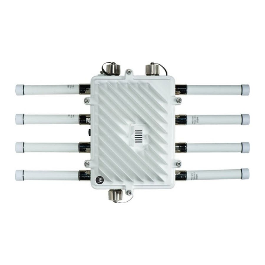
Page 22: Ap-7161 Connections And Ports
This section shows the connections and ports on the AP-7161 access point. Antenna Connectors The AP-7161 is configured with eight N type male connectors to support two or three active radios. Mount the 2.4 GHz antennas on the connectors marked R1-A, R1-B and R1-C. -
Page 23: Console, Ge1/Poe And Ge2 Ports
When making connections using these ports, a properly rated RJ45 connector is required. One Weatherproof RJ45 plug kit is provided with each access point. When connecting cables to the AP-7161 Ethernet ports, follow the instructions in the connector packaging and tighten the connectors to create a weatherproof seal. Shielded cables are required. -
Page 24: Grounding Screw
The grounding screw is located to the right of the GE1/POE port and above the GND symbol. The grounding cable for an AP-7161 must be a #10 gauge wire cross section. The cable can be attached to the unit using one of the three recommended methods: Loosen the grounding screw, insert the grounding cable into the hole below it, and tighten the screw. -
Page 25: Led Indicators
AP-7161 Access Point Installation Guide LED Indicators The AP-7161 has six LEDs on the top of the access point housing. The access point utilizes two (different colored) lights below each LED. Only one light displays within a LED at any given time. -
Page 26: Three Radio Leds
AP-7161 Access Point Installation Guide The top housing LEDs have the following display and functionality: Three Radio LEDs A three radio access point has the following unique LED behavior: LED 1 LED 2 (LAN) LED 3 (WAN) LED 4 - 5 GHz LED 5 - 2.4 GHz... -
Page 27: Dual Radio Leds
AP-7161 Access Point Installation Guide Dual Radio LEDs A dual radio model access point has the following unique LED behavior: LED 1 LED 2 (LAN) LED 3 ((WAN) LED 4 - 5 GHz LED 5 - 2.4 GHz LED 6... -
Page 28: Installing The Power-Over Ethernet (Poe) Unit
The AP-7161 can be powered by a standalone Gigabit PoE injector or from a Motorola Solutions LAN controller. A standard CAT5E cable can be used to provide the connection. When connecting to the GE1/POE port on the AP-7161, you must use the weatherproof RJ-45 plug kit that comes with the unit and it must be properly installed to maintain a weatherproof seal. -
Page 29: Poe Interface Connections
Pre-installed 5m power cable with main plug. Installing the PoE Unit When making connecting the PoE unit to the AP-7161 GE1/POE port, a properly rated RJ45 connector is required. Tighten the connectors to create a weatherproof seal. To connect the PoE unit to the access point: Connect the DATA IN jack to the GE1/POE connector. -
Page 30: Basic Ap-7161 Configuration
AP-7161 Access Point Installation Guide The AP-7161 can also be connected directly to a Motorola Solutions controller if it is located within 100 meters of the controller and a PoE port is available. If the CAT5E cable used to connect the radio and the controller has to travel though a building... - Page 31 AP-7161 Access Point Installation Guide Environmental Specifications Operating Temperature -40 to +70 degrees celsius Storage Temperature -40 to +85 degrees celsius Operating Humidity 5-100 percent Operating Altitude 8,000 feet Storage Altitude 30,000 feet Electrostatic Discharge (ESD) Outdoor IP67 rated, corrosion resistant enclosure...
- Page 32 EN 302 502 DFS EN 300 328 Industry Canada China SRRC Australia/New Zealand Safety* UL 60950-1, -22 CSA C22.2 No.60950-1-07, -22 CB-IEC 60950 -1, 22 EN 60950-1:2006+ A11:2009 RoHS/WEE/CMM * For more country specific regulatory information please contact Motorola Solutions.
- Page 33 • IP66 outdoor rated 802.3AT power injector • Mounting kit for outdoor IP 66 802.3AT power injector • External antenna options Warranty • One (1) year on AP-7161 hardware (accessories not included) • (30) day on accessories • (90) day on software...
-
Page 34: Regulatory Compliance
Motorola Solutions, Inc. (collectively “Motorola”). All Motorola Solutions devices are designed to be compliant with rules and regulations in locations they are sold and will be labeled as required. Any changes or modifications to Motorola Solutions equipment, not expressly approved by Motorola Solutions, could void the user's authority to operate the equipment. -
Page 35: Rf Exposure Guidelines
AP-7161 Access Point Installation Guide RF Exposure Guidelines Safety Information The device complies with internationally recognized standards covering human exposure to electromagnetic fields from radio devices. Reduce RF Exposure - Use Properly Only operate the device in accordance with the instructions supplied. -
Page 36: Radio Transmitters (Part 15)
• Italy requires a user license for outside usage Statement of Compliance Motorola Solutions hereby declares that this device is in compliance with the essential requirements and other relevant provisions of Directive 1999/5/EC. A Declaration of Conformity may be obtained from http://www.motorola.com/doc. -
Page 37: Korea Warning Statement For Class B
Regulatory Declarations for AP-7161 - BRAZIL Note: The certification mark applied to the AP-7161 is for Restrict Radiation Equipment. This equipment operates on a secondary basis and does not have the right for protection against harmful interference from other users including same equipment types. - Page 38 AP-7161 Access Point Installation Guide Article 14 The low power radio-frequency devices shall not influence aircraft security and interfere with legal communications; If found, the user shall cease operating immediately until no interference is achieved. The said legal communications means radio communications are operated in compliance with the Telecommunications Act.
-
Page 39: Waste Electrical And Electronic Weee
AP-7161 Access Point Installation Guide Waste Electrical and Electronic WEEE English: For EU Customers: All products at the end of their life must be returned to Symbol for recycling. Dansk: Til kunder i EU: Alle produkter skal returneres til Symbol til recirkulering, når de er udtjent. -
Page 40: Motorola's Enterprise Mobility Support Center
• Software type and version number Motorola Solutions responds to calls by e-mail, telephone, or fax within the time limits set forth in support agreements. If you purchased your product from a Motorola Solutions business partner, contact that business partner for support. -
Page 41: Ap-7161 Series Rohs Compliance
(Cables and Cable Assemblies) 塑料和聚合物部件 (Plastic and Polymeric Parts) 光学和光学组件 (Optics and Optical Components) 电池 (Batteries) O:表示该有毒有害物质在该部件所有均质材料中的含量均在 SJ/T11363-2006 标准规定的限量要求以下。 X: 表示该有毒有害物质至少在该部件的某一均质材料中的含量超出 SJ/T11363-2006 标准规定的限量要求。 对销售之日的所售产品,本表表示,公司供应链的电子信息产品可能包含这些物质。注意:在所售产品中可能会也 可能不会含有所有所列的部件。 This table was created to comply with China RoHS requirements for the Motorola Solutions AP-7161 model access point. - Page 42 AP-7161 Access Point Installation Guide...
- Page 43 AP-7161 Access Point Installation Guide...
- Page 44 Schaumburg, IL 60196-1078, U.S.A. http://www.motorolasolutions.com MOTOROLA, MOTO, MOTOROLA SOLUTIONS and the Stylized M Logo are trademarks or registered trademarks of Motorola Trademark Holdings, LLC and are used under license. All other trademarks are the property of their respective owners. © 2011 Motorola Solutions, Inc. All Rights Reserved.