Advertisement
Quick Links
Download this manual
See also:
Manual
Cisco 4G Indoor Ceiling-Mount
Omnidirectional Antenna
(4G-ANTM-OM-CM)
This document outlines the specifications and describes the 4G-ANTM-OM-CM multiband omnidirectional ceiling-mount antenna and contains the
following sections:
Overview
System Requirements
Installation Notes
Safety Instructions
Installation Instructions
Obtaining Documentation
Overview
The 4G-ANTM-OM-CM antenna is a ceiling-mount omnidirectional antenna that operates in any of the 3G or 4G bands. These bands cover the
following frequencies: 700, 800, 900, 1700, 1800, 1900, 2100,and 2600 MHz.
This antenna is designed for use with Cisco 3G cellular Enhanced High-Speed WAN Interface Cards (EHWICs) and is compatible with Cisco 3G
cellular products using a threaded Neill-Concelman (TNC) Male connector.
Cisco Systems, Inc.
www.cisco.com
302
Advertisement

Related Manuals for Cisco 4G-ANTM-OM-CM


Summary of Contents for Cisco 4G-ANTM-OM-CM
- Page 1 Obtaining Documentation Overview The 4G-ANTM-OM-CM antenna is a ceiling-mount omnidirectional antenna that operates in any of the 3G or 4G bands. These bands cover the following frequencies: 700, 800, 900, 1700, 1800, 1900, 2100,and 2600 MHz. This antenna is designed for use with Cisco 3G cellular Enhanced High-Speed WAN Interface Cards (EHWICs) and is compatible with Cisco 3G cellular products using a threaded Neill-Concelman (TNC) Male connector.
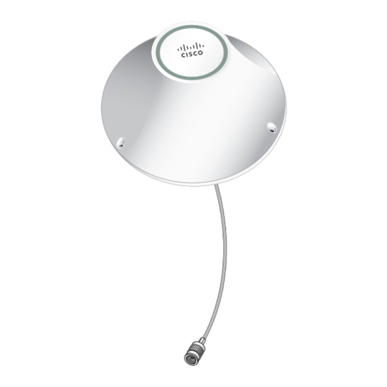
- Page 2 Running H/F 1 Running H/F 2 Figure 1 shows a front view of the 4G-ANTM-OM-CM antenna. The green circle around the Cisco logo means that this is a 4G antenna. Figure 1 Cisco 4G-ANTM-OM-CM Antenna (Front View)
- Page 3 Running H/F 1 Running H/F 2 Figure 2 shows a side view of the 4G-ANTM-OM-CM antenna. Figure 2 Cisco 4G-ANTM-OM-CM Antenna (Side View) Mounting screws and anchors (#6 x 1-1/4”) for Mounting nut mounting on a hard ceiling Self-adhesive screw covers...
-
Page 4: Technical Specifications
Running H/F 1 Running H/F 2 Figure 3 shows a top view of the 4G-ANTM-OM-CM antenna. Figure 3 Cisco 4G-ANTM-OM-CM Antenna (Top View) Technical Specifications The following table lists the technical specifications for the 4G-ANTM-OM-CM antenna. - Page 5 Running H/F 1 Running H/F 2 Antenna type Low profile, ceiling-mount omnidirectional Operating frequency range 698–806 MHz 824–894 MHz 925 –960 MHz 1575 MHz 1710–1885 MHz 1920–1980 MHz 2110–2170 MHz 2500–2690 MHz Nominal Impedance 50 Ohms ...
- Page 6 Running H/F 1 Running H/F 2 Figure 4 shows the azimuth plane patterns for the 700 MHz band for the 4G-ANTM-OM-CM antenna. Figure 4 Azimuth Plane Patterns for the 700 MHz Band...
- Page 7 Running H/F 1 Running H/F 2 Figure 5 shows the azimuth plane patterns for the 800 MHz band for the 4G-ANTM-OM-CM antenna. Figure 5 Azimuth Plane Patterns for the 800 MHz Band...
- Page 8 Running H/F 1 Running H/F 2 Figure 6 shows the azimuth plane patterns for the 900 MHz band for the 4G-ANTM-OM-CM antenna. Figure 6 Azimuth Plane Patterns for the 900 MHz Band...
- Page 9 Running H/F 1 Running H/F 2 Figure 7 shows the azimuth plane patterns for the 1700 MHz band for the 4G-ANTM-OM-CM antenna. Figure 7 Azimuth Plane Patterns for the 1700 MHz Band...
- Page 10 Running H/F 1 Running H/F 2 Figure 8 shows the azimuth plane patterns for the 1800 MHz band for the 4G-ANTM-OM-CM antenna. Figure 8 Azimuth Plane Patterns for the 1800 MHz Band...
- Page 11 Running H/F 1 Running H/F 2 Figure 9 shows the azimuth plane patterns for the 1900 MHz band for the 4G-ANTM-OM-CM antenna. Figure 9 Azimuth Plane Patterns for the 1900 MHz Band...
- Page 12 Running H/F 1 Running H/F 2 Figure 10 shows the azimuth plane patterns for the 2100 MHz band for the 4G-ANTM-OM-CM antenna. Figure 10 Azimuth Plane Patterns for the 2100 MHz Band...
- Page 13 Running H/F 1 Running H/F 2 Figure 11 shows the azimuth plane patterns for the 2600 MHz band for the 4G-ANTM-OM-CM antenna. Figure 11 Azimuth Plane Patterns for the 2600 MHz Band...
- Page 14 Running H/F 2 Figure 12 shows the elevation plane patterns (Phi = 0 degree plane cut) for the 700 MHz band for the 4G-ANTM-OM-CM antenna. Figure 12 Elevation Plane Patterns (Phi = 0 degree Plane Cut) for the 700 MHz Band...
- Page 15 Running H/F 2 Figure 13 shows the elevation plane patterns (Phi = 0 degree plane cut) for the 800 MHz band for the 4G-ANTM-OM-CM antenna. Figure 13 Elevation Plane Patterns (Phi = 0 degree Plane Cut) for the 800 MHz Band...
- Page 16 Running H/F 2 Figure 14 shows the elevation plane patterns (Phi = 0 degree plane cut) for the 900 MHz band for the 4G-ANTM-OM-CM antenna. Figure 14 Elevation Plane Patterns (Phi = 0 degree Plane Cut) for the 900 MHz Band...
- Page 17 Running H/F 2 Figure 15 shows the elevation plane patterns (Phi = 0 degree plane cut) for the 1700 MHz band for the 4G-ANTM-OM-CM antenna. Figure 15 Elevation Plane Patterns (Phi = 0 degree Plane Cut) for the 1700 MHz Band...
- Page 18 Running H/F 2 Figure 16 shows the elevation plane patterns (Phi = 0 degree plane cut) for the 1800 MHz band for the 4G-ANTM-OM-CM antenna. Figure 16 Elevation Plane Patterns (Phi = 0 degree Plane Cut) for the 1800 MHz Band...
- Page 19 Running H/F 2 Figure 17 shows the elevation plane patterns (Phi = 0 degree plane cut) for the 1900 MHz band for the 4G-ANTM-OM-CM antenna. Figure 17 Elevation Plane Patterns (Phi = 0 degree Plane Cut) for the 1900 MHz Band...
- Page 20 Running H/F 2 Figure 18 shows the elevation plane patterns (Phi = 0 degree plane cut) for the 2100 MHz band for the 4G-ANTM-OM-CM antenna. Figure 18 Elevation Plane Patterns (Phi = 0 degree Plane Cut) for the 2100 MHz Band...
- Page 21 Running H/F 2 Figure 19 shows the elevation plane patterns (Phi = 0 degree plane cut) for the 2600 MHz band for the 4G-ANTM-OM-CM antenna. Figure 19 Elevation Plane Patterns (Phi = 0 degree Plane Cut) for the 2600 MHz Band...
- Page 22 Running H/F 2 Figure 20 shows the elevation plane patterns (Phi = 90 degree plane cut) for the 700 MHz band for the 4G-ANTM-OM-CM antenna. Figure 20 Elevation Plane Patterns (Phi = 90 degree Plane Cut) for the 700 MHz Band...
- Page 23 Running H/F 2 Figure 21 shows the elevation plane patterns (Phi = 90 degree plane cut) for the 800 MHz band for the 4G-ANTM-OM-CM antenna. Figure 21 Elevation Plane Patterns (Phi = 90 degree Plane Cut) for the 800 MHz Band...
- Page 24 Running H/F 2 Figure 22 shows the elevation plane patterns (Phi = 90 degree plane cut) for the 900 MHz band for the 4G-ANTM-OM-CM antenna. Figure 22 Elevation Plane Patterns (Phi = 90 degree Plane Cut) for the 900 MHz Band...
- Page 25 Running H/F 2 Figure 23 shows the elevation plane patterns (Phi = 90 degree plane cut) for the 1700 MHz band for the 4G-ANTM-OM-CM antenna. Figure 23 Elevation Plane Patterns (Phi = 90 degree Plane Cut) for the 1700 MHz Band...
- Page 26 Running H/F 2 Figure 24 shows the elevation plane patterns (Phi = 90 degree plane cut) for the 1800 MHz band for the 4G-ANTM-OM-CM antenna. Figure 24 Elevation Plane Patterns (Phi = 90 degree Plane Cut) for the 1800 MHz Band...
- Page 27 Running H/F 2 Figure 25 shows the elevation plane patterns (Phi = 90 degree plane cut) for the 1900 MHz band for the 4G-ANTM-OM-CM antenna. Figure 25 Elevation Plane Patterns (Phi = 90 degree Plane Cut) for the 1900 MHz Band...
- Page 28 Running H/F 2 Figure 26 shows the elevation plane patterns (Phi = 90 degree plane cut) for the 2100 MHz band for the 4G-ANTM-OM-CM antenna. Figure 26 Elevation Plane Patterns (Phi = 90 degree Plane Cut) for the 2100 MHz Band...
-
Page 29: System Requirements
Running H/F 2 Figure 27 shows the elevation plane patterns (Phi = 90 degree plane cut) for the 2600 MHz band for the 4G-ANTM-OM-CM antenna. Figure 27 Elevation Plane Patterns (Phi = 90 degree Plane Cut) for the 2600 MHz Band System Requirements The 4G-ANTM-OM-CM antenna requires a Cisco 3G EHWIC that uses a TNC-Male connector. -
Page 30: Safety Instructions
Running H/F 1 Running H/F 2 — Paper and vinyl walls have very little effect on signal penetration. — Solid and precast concrete walls limit signal penetration to one or two walls without degrading coverage. — Concrete and wood block walls limit signal penetration to three or four walls. —... -
Page 31: Installation Instructions
To extend the coaxial cable included with your antenna, we recommend an ultra-low-loss coaxial cable for installation flexibility without a significant loss in range. The following table lists insertion loss information about ULL extension coaxial cables available from Cisco. Cisco Product Number... -
Page 32: Obtaining Documentation
Installation Instructions for the Cisco 4G-ANTM-OM-CM Antenna Router Obtaining Documentation Cisco documentation and additional literature are available on Cisco.com. Cisco also provides several ways to obtain technical assistance and other technical resources. These sections explain how to obtain technical information from Cisco Systems. Cisco.com... - Page 33 Cisco and the Cisco logo are trademarks or registered trademarks of Cisco and/or its affiliates in the U.S. and other countries. To view a list of Cisco trademarks, go to this URL: www.cisco.com/go/trademarks. Third-party trademarks mentioned are the property of their respective owners. The use of the word partner does not imply a partnership relationship between Cisco and any other company.
- Page 34 Running H/F 1 Running H/F 2...